A battery with EMF E and internal resistance r is connected across a resistance R. The power consumption in R will be maximum when :
JEE EMF & Circuit Analysis Questions
We begin with a battery with EMF $$E$$ and internal resistance $$r$$ connected across an external resistance $$R$$, and we need to find the value of $$R$$ for which the power consumed in $$R$$ is maximum.
Applying Ohm's law to the complete circuit, the current is:
$$ I = \frac{E}{R + r} $$
The power consumed in the external resistance $$R$$ is:
$$ P = I^2 R = \left(\frac{E}{R + r}\right)^2 R = \frac{E^2 R}{(R + r)^2} $$
To find its maximum, we differentiate with respect to $$R$$ using the quotient rule, with numerator $$E^2 R$$ and denominator $$(R + r)^2$$:
$$ \frac{dP}{dR} = E^2 \cdot \frac{(R + r)^2 \cdot 1 - R \cdot 2(R + r)}{(R + r)^4} $$
This simplifies to:
$$ = E^2 \cdot \frac{(R + r) - 2R}{(R + r)^3} = E^2 \cdot \frac{r - R}{(R + r)^3} $$
Setting $$\frac{dP}{dR} = 0$$ gives:
$$ r - R = 0 $$
$$ R = r $$
For $$R < r$$, $$\frac{dP}{dR} > 0$$ (power is increasing)
For $$R > r$$, $$\frac{dP}{dR} < 0$$ (power is decreasing)
Since the derivative changes from positive to negative at $$R = r$$, this confirms it is a maximum.
This result is known as the Maximum Power Transfer Theorem: maximum power is delivered to the external load when the load resistance equals the internal resistance of the source.
The correct answer is Option (1): $$R = r$$.
A Wheatstone bridge is initially at room temperature and all arms of the bridge have same value of resistances $$(R_{1}=R_{2}=R_{3}=R_{4})$$. When $$R_{3}$$ resistance is heated to some temperature, its resistance value has gone up by 10%. The potential difference $$(V_{a}-V_{b})$$ (after $$R_{3}$$ is heated) is ____ V.
Let the initial resistance of all arms be $$R$$.
$$ R_1 = R_2 = R_4 = R_3=R $$
After heating, the resistance of $$R_3$$ increases by 10%.
$$ R_3 = R + 0.1R = 1.1R $$
The potential at node $$a$$ ($$V_a$$) is determined by the voltage divider of $$R_1$$ and $$R_2$$ across the 40 V source.
$$ V_a = 40 \times \frac{R_2}{R_1 + R_2} $$
$$ V_a = 40 \times \frac{R}{R + R} $$
$$ V_a = 20 \text{ V} $$
The potential at node $$b$$ ($$V_b$$) is determined by the voltage divider of $$R_3$$ and $$R_4$$ across the same 40 V source.
$$ V_b = 40 \times \frac{R_4}{R_3 + R_4} $$
$$ V_b = 40 \times \frac{R}{1.1R + R} $$
$$ V_b = 40 \times \frac{1}{2.1} $$
$$ V_b = \frac{400}{21} \text{ V} $$
The potential difference $$(V_a - V_b)$$ is calculated as:
$$ V_a - V_b = 20 - \frac{400}{21} $$
$$ V_a - V_b = \frac{420 - 400}{21} $$
$$ V_a - V_b = \frac{20}{21} \text{ V} $$
=0.95V
In the potentiometer, when the cell in the secondary circuit is shunted with 4Ω resistance, the balance is obtained at the length 120 cm of wire. Now when the same cell is shunted with 12Ω resistance, the balance is shifted to a length of 180 cm. The internal resistance of cell is_________Ω
We need to find the internal resistance of a cell using potentiometer readings with two different shunt resistances.
Formula: When cell is shunted with resistance S, the balance length is:
$$l = \frac{E \cdot S}{S + r} \times k$$ (where k is a constant depending on the potentiometer)
For shunt S₁ = 4Ω: $$l_1 = 120$$ cm → $$120 = \frac{E \times 4}{4+r} \times k$$
For shunt S₂ = 12Ω: $$l_2 = 180$$ cm → $$180 = \frac{E \times 12}{12+r} \times k$$
Taking the ratio:
$$\frac{120}{180} = \frac{4/(4+r)}{12/(12+r)} = \frac{4(12+r)}{12(4+r)}$$
$$\frac{2}{3} = \frac{4(12+r)}{12(4+r)} = \frac{12+r}{3(4+r)}$$
$$2 \times 3(4+r) = 3(12+r)$$
$$6(4+r) = 3(12+r)$$
$$24 + 6r = 36 + 3r$$
$$3r = 12$$
$$r = 4 \, \Omega$$
Therefore, the internal resistance is Option 3: 4 Ω.
To compare EMF of two cells using potentiometer the balancing lengths obtained are 200 cm and 150 cm. The least count of scale is 1 cm. The percentage error in the ratio of EMFs is______
For a potentiometer:
E₁ / E₂ = l₁ / l₂
Given:
l₁ = 200 cm
l₂ = 150 cm
least count = ±1 cm → absolute error in each length = 1 cm
step 1: relative error in ratio
$$\frac{\Delta(E_1/E_2)}{E_1/E_2}=\frac{\Delta l_1}{l_1}+\frac{\Delta l_2}{l_2}=\frac{1}{200}+\frac{1}{150}$$
step 2: calculate
$$\frac{1}{200}=0.005$$
$$\frac{1}{150}\approx0.00667$$
sum:
0.005 + 0.00667 = 0.01167
step 3: percentage error
$$0.01167\times100\approx1.17\%$$
For the two cells having same EMF E and internal resistance r, the current passing through the external resistor 6Ω is same when both the cells are connected either in parallel or in series. The value of internal resistance r is ____ Ω .
Two identical cells (each with EMF $$E$$ and internal resistance $$r$$) give the same current through an external resistance of $$6\Omega$$ whether connected in series or parallel. We need to find $$r$$.
Current in series connection.
In series, the total EMF is $$2E$$ and total internal resistance is $$2r$$:
$$ I_{series} = \frac{2E}{2r + 6} $$
Current in parallel connection.
In parallel, the equivalent EMF is $$E$$ and equivalent internal resistance is $$\frac{r}{2}$$ (two identical resistances $$r$$ in parallel):
$$ I_{parallel} = \frac{E}{\frac{r}{2} + 6} = \frac{2E}{r + 12} $$
Set the currents equal and solve.
$$ \frac{2E}{2r + 6} = \frac{2E}{r + 12} $$
Cancel $$2E$$ from both sides:
$$ \frac{1}{2r + 6} = \frac{1}{r + 12} $$
$$ 2r + 6 = r + 12 $$
$$ r = 6 \, \Omega $$
The correct answer is Option (3): 6 $$\Omega$$.
The reading of the ammeter (A) in steady state in the following circuit (assuming negligible internal resistance of the ammeter) is ___ A.
after removing capacitor branch:(as in steady state capacitor is an open circuit)
- from middle node → one 8Ω to bottom
- from middle → 4Ω → right node
- right node → two 8Ω in parallel to bottom
step 1: right side
$$8||8=4\Omega$$
step 2: path via right:
$$4+4=8\Omega$$
so from middle node to bottom we have:
$$8\Omega\text{ (direct)}\parallel8\Omega\text{ (via right)}$$
R=4Ω
step 3: total resistance:
$$R_{total}=1+4=5Ω$$
step 4: current:
$$I=\frac{10}{5}=2A$$
current splits equally in two branches so answer is 1A
Refer to the figure given below. The values of $$I_1$$, $$I_2$$ and $$I_3$$ are _______.
A voltmeter with internal resistance of $$x \; \Omega$$ can be used to measure upto 20 V. In order to increase its measuring range to 30 V, the required modification is :
A voltmeter is basically a galvanometer designed to draw as little current as possible from the circuit under test. Its scale is calibrated such that the full-scale deflection occurs when the potential difference across its own (internal) resistance is equal to the rated range.
Given data for the original voltmeter:
internal resistance $$R_v = x \,\Omega$$
maximum readable voltage (full-scale) $$V_{\text{old}} = 20 \text{ V}$$
We want to extend the range to a new value
$$V_{\text{new}} = 30 \text{ V}$$
Method: Add a resistance in series (called a multiplier resistance) so that the larger voltage is divided between the voltmeter and the added resistor, while the same full-scale current still flows through the meter.
Let the required series resistance be $$R_s$$. At full-scale current $$I_{\text{fs}}$$ we have:
For the original meter alone:
$$I_{\text{fs}} = \frac{V_{\text{old}}}{R_v} = \frac{20}{x} \quad -(1)$$
After adding $$R_s$$ in series, the same current $$I_{\text{fs}}$$ must flow when the applied voltage is $$V_{\text{new}} = 30 \text{ V}$$:
$$V_{\text{new}} = I_{\text{fs}}\,(R_v + R_s) \quad -(2)$$
Substitute $$I_{\text{fs}}$$ from $$(1)$$ into $$(2)$$:
$$30 = \frac{20}{x}\,(R_v + R_s)$$
But $$R_v = x$$, so
$$30 = \frac{20}{x}\,(x + R_s) \; \Longrightarrow \; 30 = 20\left(1 + \frac{R_s}{x}\right)$$
Divide both sides by 20:
$$\frac{30}{20} = 1 + \frac{R_s}{x} \;\; \Longrightarrow \;\; \frac{3}{2} = 1 + \frac{R_s}{x}$$
Hence
$$\frac{R_s}{x} = \frac{3}{2} - 1 = \frac{1}{2}$$
$$\Rightarrow \; R_s = \frac{x}{2}$$
Therefore, connecting a series resistor of $$\dfrac{x}{2}\,\Omega$$ extends the voltmeter range from 20 V to 30 V.
Adding any resistor in parallel would reduce, not increase, the effective resistance and hence the measurable voltage, so options B and D are unsuitable. Option C gives too high a value, leading to a 40-V range. Thus the correct choice is:
Option A which is: connect resistor of $$\frac{x}{2} \; \Omega$$ in series.
Under steady state condition the potential difference across the capacitor in the circuit is________ V.
Refer to the figure given below, current between terminals $$A$$ and $$B$$ is _______A.
Look at one horizontal branch (top/middle/bottom):
each branch has
3 cells of 5 V and 3 resistors of 3 Ω in series
so for each branch:
net emf = 5 + 5 + 5 = 15 V
total resistance = 3 + 3 + 3 = 9 Ω
so current in each such branch (if isolated):
I = 15 / 9 = 5/3 A
Now there are 3 identical branches in parallel, all between the same left and right nodes
so total current from these three:
$$I_{total}(top\ part)=3\times(5/3)=5A$$
bottom branch (A to B):
only resistors: 3 + 3 + 3 = 9 Ω
no battery
so it behaves like a resistor connected across the same two nodes
Now the three upper branches together act like a single source supplying 5 A between the nodes
this current must pass through the bottom 9 Ω path
so:
I = 5 A
Two resistors 2Ω and 3Ω are connected in the gaps of bridge as shown in figure. The null point is obtained with the contact of jockey at some point on wire XY. When an unknown resistor is connected in parallel with 3Ω resistor, the null point is shifted by 22.5 cm toward Y. The resistance of unknown resistor is ____ Ω .
Let the initial balancing length from end $$X$$ be $$l_1$$.
$$ \frac{R_1}{l_1} = \frac{R_2}{100 - l_1} $$
$$ \frac{2}{l_1} = \frac{3}{100 - l_1} $$
$$ 2(100 - l_1) = 3l_1 $$
$$ 200 - 2l_1 = 3l_1 $$
$$ 5l_1 = 200 \implies l_1 = 40 \text{ cm} $$
An unknown resistor $$R$$ is connected in parallel with the $$3 \, \Omega$$ resistor. The new equivalent resistance in the right gap ($$R_2'$$) is:
$$ R_2' = \frac{3R}{3 + R} $$
The null point shifts by $$22.5 \text{ cm}$$ towards $$Y$$. This means the new balancing length $$l_2$$ increases:
$$ l_2 = l_1 + 22.5 = 40 + 22.5 = 62.5 \text{ cm} $$
Applying the meter bridge principle for the new state:
$$ \frac{2}{l_2} = \frac{R_2'}{100 - l_2} $$
$$ \frac{2}{62.5} = \frac{R_2'}{100 - 62.5} $$
$$ \frac{2}{62.5} = \frac{R_2'}{37.5} $$
$$ R_2' = 2 \times \left( \frac{37.5}{62.5} \right) $$
$$ R_2' = 2 \times \left( \frac{3}{5} \right) = \frac{6}{5} \, \Omega $$
$$ \frac{3R}{3 + R} = \frac{6}{5} $$
$$ 15R = 6(3 + R) $$
$$ 9R = 18 $$
$$ R = 2 \, \Omega $$
Two resistors of 200 $$\Omega$$ and 400 $$\Omega$$ are connected in series with a battery of 100 V. A bulb rated at 200 V, 100 W is connected across the 400 $$\Omega$$ resistance. The potential drop across the bulb is :
The bulb is not connected directly across the battery; it is placed in parallel with the $$400\;\Omega$$ resistor, and this parallel pair is in series with the $$200\;\Omega$$ resistor and the 100 V source.
Step 1 Find the resistance of the bulb.
The rating 200 V, 100 W means the bulb draws 100 W when 200 V is applied.
Using $$P = \frac{V^{2}}{R}$$, the resistance of the bulb is
$$R_{b} = \frac{(200)^{2}}{100} = 400\;\Omega$$.
Step 2 Find the equivalent resistance of the parallel branch.
The bulb ($$R_{b}=400\;\Omega$$) is in parallel with the given $$400\;\Omega$$ resistor $$R_{2}$$.
For two equal resistances in parallel,
$$R_{\text{parallel}} = \frac{R_{b}\,R_{2}}{R_{b}+R_{2}}
= \frac{400 \times 400}{400+400}
= \frac{160000}{800}
= 200\;\Omega$$.
Step 3 Find the total resistance seen by the battery.
This parallel combination ($$200\;\Omega$$) is in series with the $$200\;\Omega$$ resistor $$R_{1}$$:
$$R_{\text{total}} = R_{1} + R_{\text{parallel}}
= 200 + 200
= 400\;\Omega$$.
Step 4 Calculate the circuit current.
Using Ohm’s law with the 100 V source:
$$I = \frac{V}{R_{\text{total}}}
= \frac{100}{400}
= 0.25\;\text{A}$$.
Step 5 Find the potential drop across the bulb.
The bulb shares the same potential as its parallel partner, so
$$V_{\text{bulb}} = I \times R_{\text{parallel}}
= 0.25 \times 200
= 50\;\text{V}$$.
Hence, the potential drop across the bulb is $$50\;\text{V}$$.
Option B which is: $$50\;\text{V}$$
A circular loop of radius 7 cm is placed in uniform magnetic field of 0.2 T directed perpendicular to plane of loop. The loop is converted into a square loop in 0.5 s.
The EMF induced in the loop is ____ mV.
We need to find the EMF induced when a circular loop is converted into a square loop in a magnetic field.
By Faraday’s law of electromagnetic induction, the EMF is given by $$\text{EMF} = -\frac{d\Phi}{dt} = -B\frac{dA}{dt} \approx B\frac{|\Delta A|}{\Delta t}$$, where $$\Phi = BA$$ is the magnetic flux (since $$B$$ is uniform and perpendicular to the loop), and $$\Delta A$$ is the change in area.
First, the area of the circular loop is calculated. With radius $$r = 7 \, \text{cm} = 0.07 \, \text{m}$$, we have $$A_{\text{circle}} = \pi r^2 = \pi \times (0.07)^2 = \pi \times 0.0049 = 0.015394 \, \text{m}^2$$.
Next, when the wire is reshaped into a square, its perimeter remains equal to that of the original circle. Since the circumference is $$2\pi r = 2\pi \times 0.07 = 0.4398 \, \text{m}$$, each side of the square measures $$\frac{2\pi r}{4} = \frac{\pi r}{2} = \frac{\pi \times 0.07}{2} = 0.10996 \, \text{m}$$.
Accordingly, the area of the square becomes $$A_{\text{square}} = \left(\frac{\pi r}{2}\right)^2 = \frac{\pi^2 r^2}{4} = \frac{\pi^2 \times 0.0049}{4} = \frac{0.04835}{4} = 0.012088 \, \text{m}^2$$.
Therefore, the change in area is $$|\Delta A| = A_{\text{circle}} - A_{\text{square}} = 0.015394 - 0.012088 = 0.003306 \, \text{m}^2$$.
Finally, substituting this into Faraday’s law yields $$\text{EMF} = B \times \frac{|\Delta A|}{\Delta t} = 0.2 \times \frac{0.003306}{0.5} = 0.2 \times 0.006612 = 0.001322 \, \text{V}$$, or equivalently $$\text{EMF} = 1.32 \, \text{mV}$$.
The correct answer is Option (4): 1.32 mV.
A meter bridge with two resistances $$R_{1}$$ and $$R_{2}$$ as shown in figure was balanced (null point) at 40 cm from the point $$P$$. The null point changed to 50 cm from the point $$P$$, when 16 $$\Omega$$ resistance is connected in parallel to $$R_{2}$$. The values of resistances $$R_{1}$$ and $$R_{2}$$ are ______
step 1: initial balance
Null point at 40 cm from P, so
R₁ / R₂ = 40 / (100 − 40) = 40 / 60 = 2 / 3
So,
R₁ = (2/3) R₂ … (1)
step 2: after adding 16 Ω in parallel with R₂
New null point = 50 cm → perfectly centered
So,
R₁ / (R₂ || 16) = 50 / 50 = 1
That means:
R₁ = R₂ || 16
Equivalent of parallel:
R₂ || 16 = (16R₂) / (R₂ + 16)
So,
R₁ = (16R₂) / (R₂ + 16) … (2)
step 3: substitute (1) into (2)
(2/3)R₂ = (16R₂) / (R₂ + 16)
Cancel R₂:
2/3 = 16 / (R₂ + 16)
Cross multiply:
2(R₂ + 16) = 48
2R₂ + 32 = 48
2R₂ = 16
R₂ = 8 Ω
step 4: find R₁
R₁ = (2/3) × 8 = 16/3 Ω
Two resistors of 100Ω each are connected in series with a 9 V batte1y. A voltmeter of 400Ω resistance is connected to measure the voltage drop across one of the resistors. The voltmeter reading is ____ V.
We need to find the voltmeter reading when a 400 ohm voltmeter is connected across one of two 100 ohm resistors in series with a 9V battery.
Two resistors: $$R_1 = R_2 = 100 \, \Omega$$ in series
Battery voltage: $$V = 9$$ V
Voltmeter resistance: $$R_V = 400 \, \Omega$$
The voltmeter (400 ohm) is connected in parallel with one 100 ohm resistor:
$$R_{parallel} = \frac{R_1 \times R_V}{R_1 + R_V} = \frac{100 \times 400}{100 + 400} = \frac{40000}{500} = 80 \, \Omega$$
$$R_{total} = R_{parallel} + R_2 = 80 + 100 = 180 \, \Omega$$
$$I = \frac{V}{R_{total}} = \frac{9}{180} = 0.05 \text{ A}$$
$$V_{reading} = I \times R_{parallel} = 0.05 \times 80 = 4 \text{ V}$$
Therefore, the voltmeter reading is Option 1: 4 V.
The voltage and the current between A and B points shown in the circuit are :
Two known resistances of $$R \Omega$$ and $$2R \Omega$$ and one unknown resistance $$X \Omega$$ are connected in a circuit as shown in the figure. If the equivalent resistance between points A and B in the circuit is $$X \Omega$$, then the value of X is __________ $$\Omega$$.
From the diagram, there are two parallel paths between A and B:
• bottom branch: just R
• top branch: 2R in series with X → total = 2R + X
So equivalent resistance:
$$R_{eq}=\frac{\left(R(2R+X)\right)}{(R+2R+X)}$$
Given: Req = X
So,
$$R(2R+X)/(3R+X)=X$$
Cross-multiply:
$$R(2R+X)=X(3R+X)$$
Expand:
$$2R^2+RX=3RX+X^2$$
Bring everything to one side:
$$2R^2+RX−3RX−X^2=0$$
$$2R^2−2RX−X^2=0$$
Rearrange:
$$X^2+2RX−2R^2=0$$
Now solve quadratic in X:
$$X=[−2R\pm\sqrt{(4R^2+8R^2)}]/2$$
$$X=[−2R\pm\sqrt{\ 12R^2}]/2$$
$$X=[−2R\pm2\sqrt{3}R]/2$$
$$X=−R\pm\sqrt{3}R$$
Physical resistance must be positive, so:
$$X=R(\sqrt{3}−1)$$
A simple pendulum made of mass 10 g and a metallic wire of length 10 cm is suspended vertically in a uniform magnetic field of 2 T. The magnetic field direction is perpendicular to the plane of oscillations of the pendulum. If the pendulwn is released from an angle of 60° with vertical, then maximum induced EMF between the point of s uspension and point of oscillation is ______mV (Take $$g= 10 m/s^{2}$$)
The pendulum consists of a metallic wire of length $$L = 10 \text{ cm} = 0.1 \text{ m}$$ and a bob of mass $$m = 10 \text{ g} = 0.01 \text{ kg}$$, oscillating in a uniform magnetic field $$B = 2 \text{ T}$$ perpendicular to the plane of oscillation. The maximum induced EMF occurs when the angular velocity is maximum, which is at the lowest point of the swing.
The induced EMF in a rotating conductor of length $$L$$ about one end in a uniform magnetic field $$B$$ perpendicular to the plane of rotation is given by:
$$\mathcal{E} = \frac{1}{2} B \omega L^2$$
where $$\omega$$ is the angular velocity.
To find the maximum angular velocity $$\omega_{\text{max}}$$, use conservation of energy. The initial angle is $$\theta_0 = 60^\circ$$. The height $$h$$ above the lowest point is:
$$h = L (1 - \cos \theta_0)$$
Substitute $$\cos 60^\circ = 0.5$$:
$$h = 0.1 \times (1 - 0.5) = 0.1 \times 0.5 = 0.05 \text{ m}$$
The potential energy at the initial position converts to kinetic energy at the lowest point:
$$m g h = \frac{1}{2} m v_{\text{max}}^2$$
where $$g = 10 \text{ m/s}^2$$. Solve for $$v_{\text{max}}$$:
$$v_{\text{max}} = \sqrt{2 g h} = \sqrt{2 \times 10 \times 0.05} = \sqrt{1} = 1 \text{ m/s}$$
The maximum angular velocity $$\omega_{\text{max}}$$ is related to $$v_{\text{max}}$$ by:
$$\omega_{\text{max}} = \frac{v_{\text{max}}}{L} = \frac{1}{0.1} = 10 \text{ rad/s}$$
Now substitute into the EMF formula:
$$\mathcal{E}_{\text{max}} = \frac{1}{2} B \omega_{\text{max}} L^2 = \frac{1}{2} \times 2 \times 10 \times (0.1)^2$$
Calculate step by step:
$$(0.1)^2 = 0.01$$
$$\mathcal{E}_{\text{max}} = \frac{1}{2} \times 2 \times 10 \times 0.01 = 1 \times 10 \times 0.01 = 0.1 \text{ V}$$
Convert to millivolts: $$0.1 \text{ V} = 100 \text{ mV}$$.
Thus, the maximum induced EMF is $$100 \text{ mV}$$.
Refer to the circuit diagram given below. The heat generated across the 6 $$\Omega$$ resistance in 100 second is $$\frac{\alpha}{100}$$ J. The value of $$\alpha$$ is _______. (Nearest integer)
The heat generated in 1 minute between points A and B in the given circuit, when a battery of 9 V with internal resistance of 1Ω is connected across these points is ____ J
Wheatstone bridge between A and B.
$$R_{AB} = \dfrac{3 \times 6}{3+6}$$
$$R_{AB} = 2 \, \Omega$$
After solving we get the circuit as shown in figure
$$i = \dfrac{9}{2+1} \text{ A}$$
$$i=3A$$
$$t = 1 \text{ min} = 60 \text{ s}$$
Heat generated across a resistor $$R_{AB}$$ in time $$t$$ is $$H = i^2 R_{AB} t$$.
$$H = 9 \times 2 \times 60$$
$$H = 1080 \text{ J}$$
The stored charge in the capacitor in steady state of the following circuit is __________ $$\mu$$C.
Circuit simplification at steady state
In steady state, the capacitor branch is an open circuit. We simplify the resistance from right to left:
- Right loop series: $$4\ \Omega+4\ \Omega+2\ \Omega=10\ \Omega$$
- Parallel with middle $$10\ \Omega$$ resistor: $$\frac{10 \times 10}{10 + 10} = 5\ \Omega$$
- Middle loop series: $$5\ \Omega + 5\ \Omega + 2\ \Omega = 12\ \Omega$$
- Parallel with first $$12\ \Omega$$ resistor: $$\frac{12 \times 12}{12 + 12} = 6\ \Omega$$
Total current from the battery:
$$I_{total} = \frac{12\ V}{6\ \Omega} = 2\ A$$
- The $$2\ A$$ current splits equally at the first branch ($$12\ \Omega$$ each), so $$1\ A$$ enters the middle section.
- That $$1\ A$$ splits equally at the second branch ($$10\ \Omega$$ each), so $$0.5\ A$$ flows through the rightmost $$4\ \Omega$$ vertical resistor.
The voltage across the capacitor ($$V_{C}$$) is the same as the voltage across the $$4\ \Omega$$ vertical resistor:
$$V_{C} = 0.5\ A \times 4\ \Omega = 2\ V$$
Final charge ($$Q$$):
$$Q = C \times V_{C}$$
$$Q = 100\ \mu F \times 2\ V = 200\ \mu C$$
Two cells of emfs 1 V and 2 V and internal resistance 2 $$\Omega$$ and 1 $$\Omega$$, respectively connected in parallel, gave a current of 1 A through an external resistance. If the polarity of one cell is reversed, then value of current through the external resistance will be $$\dfrac{\alpha}{5}$$ A. The value of $$\alpha$$ is __________.
When an external resistance of $$5\,\Omega$$ is connected across terminals of a cell, a current of $$0.25$$ A flow through it. When the $$5\,\Omega$$ resistor is replaced by a $$2\,\Omega$$ resistor, a current of $$0.5$$ A flow through it. The internal resistance of the cell is________ $$\Omega$$.
A cylindrical conductor of length 2 m and area of cross-section $$0.2mm^{2}$$ carries an electric current of 1.6 A when its ends are connected to a 2 V battery. Mobility of electrons in the conductor is $$\alpha \times 10^{-3}m^{2}/V.s.$$ The value of $$\alpha$$ is :
(electron concentration = $$5 \times 10^{28}/m^{3}$$ and electron charge = $$1.6 \times 10^{-19}C$$)
We need to find the mobility of electrons in a cylindrical conductor.
The length of the conductor is $$L = 2$$ m, its cross-sectional area is $$A = 0.2$$ mm$$^2 = 0.2 \times 10^{-6}$$ m$$^2$$, the current through it is $$I = 1.6$$ A, the applied voltage is $$V = 2$$ V, the electron density is $$n = 5 \times 10^{28}$$/m$$^3$$, and the charge of an electron is $$e = 1.6 \times 10^{-19}$$ C.
Since resistance is given by $$R = \frac{V}{I} = \frac{2}{1.6} = 1.25 \text{ } \Omega$$, we obtain the resistance.
Substituting this into the formula for resistivity yields $$\rho = \frac{RA}{L} = \frac{1.25 \times 0.2 \times 10^{-6}}{2} = \frac{0.25 \times 10^{-6}}{2} = 1.25 \times 10^{-7} \text{ } \Omega \cdot m$$.
Mobility is defined by $$\mu = \frac{1}{ne\rho}$$, and substituting the known values gives
$$\mu = \frac{1}{5 \times 10^{28} \times 1.6 \times 10^{-19} \times 1.25 \times 10^{-7}}$$
$$= \frac{1}{5 \times 1.6 \times 1.25 \times 10^{28-19-7}} = \frac{1}{10 \times 10^{2}} = \frac{1}{1000} = 10^{-3} \text{ m}^2/\text{Vs}$$
So $$\alpha = 1$$.
The answer is 1.
In a meter bridge experiment to determine the value of unknown resistance, first the resistances $$2\Omega$$ and $$3\Omega$$ are connected in the left and right gaps of the bridge and the null point is obtained at a distance l cm from the left. Now when an unknown resistance $$x\Omega$$ is connected in parallel to $$3\Omega$$ resistance, the null point is shifted by 10 cm to the right of wire. The value of unknown resistance x is __________ $$\Omega$$ .
We need to find the unknown resistance x connected in parallel with 3Ω in a meter bridge.
Initially, 2Ω is on the left and 3Ω is on the right, and the null point is at a distance l from the left.
$$\frac{2}{3} = \frac{l}{100-l} \implies l = 40 \text{ cm}$$
When x is connected in parallel with the 3Ω resistor, the effective resistance on the right becomes $$R_{eff} = \frac{3x}{3+x}$$.
The null point shifts 10 cm to the right, so the new null point is at $$l' = 50$$ cm.
$$\frac{2}{\frac{3x}{3+x}} = \frac{50}{50} = 1$$
$$\frac{2(3+x)}{3x} = 1$$
$$6 + 2x = 3x$$
$$x = 6 \, \Omega$$
Therefore, x = 6 Ω.
A temperature difference can generate e.m.f. in some materials. Let $$S$$ be the e.m.f. produced per unit temperature difference between the ends of a wire, $$\sigma$$ the electrical conductivity and $$\kappa$$ the thermal conductivity of the material of the wire. Taking $$M$$, $$L$$, $$T$$, $$I$$ and $$K$$ as dimensions of mass, length, time, current and temperature, respectively, the dimensional formula of the quantity $$Z = \frac{S^2 \sigma}{\kappa}$$ is:
Given below are two statements :
Statement-I : The equivalent emf of two nonideal batteries connected in parallel is smaller than either of the two emfs.
Statement-II : The equivalent internal resistance of two nonideal batteries connected in parallel is smaller than the internal resistance of either of the two batteries. In the light of the above statements, choose the correct answer from the options given below.
To solve this problem, we need to evaluate two statements about non-ideal batteries connected in parallel. A non-ideal battery has an internal resistance, so we must consider both the electromotive force (emf) and the internal resistance for each battery.
Consider two batteries:
- Battery 1: emf = $$E_1$$, internal resistance = $$r_1$$
- Battery 2: emf = $$E_2$$, internal resistance = $$r_2$$
When connected in parallel, the equivalent emf $$E_{eq}$$ and equivalent internal resistance $$r_{eq}$$ are given by the formulas:
$$E_{eq} = \frac{E_1 r_2 + E_2 r_1}{r_1 + r_2}$$
$$r_{eq} = \frac{r_1 r_2}{r_1 + r_2}$$
We will analyze each statement separately.
Statement-II Analysis: The equivalent internal resistance of two nonideal batteries connected in parallel is smaller than the internal resistance of either of the two batteries.
Using the formula for equivalent internal resistance:
$$r_{eq} = \frac{r_1 r_2}{r_1 + r_2}$$
Since $$r_1 > 0$$ and $$r_2 > 0$$, we can compare $$r_{eq}$$ with $$r_1$$:
$$\frac{r_{eq}}{r_1} = \frac{\frac{r_1 r_2}{r_1 + r_2}}{r_1} = \frac{r_2}{r_1 + r_2} < 1$$
because $$r_2 < r_1 + r_2$$. Therefore, $$r_{eq} < r_1$$.
Similarly, comparing $$r_{eq}$$ with $$r_2$$:
$$\frac{r_{eq}}{r_2} = \frac{\frac{r_1 r_2}{r_1 + r_2}}{r_2} = \frac{r_1}{r_1 + r_2} < 1$$
so $$r_{eq} < r_2$$.
Thus, $$r_{eq}$$ is always less than both $$r_1$$ and $$r_2$$. Therefore, Statement-II is true.
Statement-I Analysis: The equivalent emf of two nonideal batteries connected in parallel is smaller than either of the two emfs.
Using the equivalent emf formula:
$$E_{eq} = \frac{E_1 r_2 + E_2 r_1}{r_1 + r_2}$$
This expression is a weighted average of $$E_1$$ and $$E_2$$:
$$E_{eq} = E_1 \cdot \frac{r_2}{r_1 + r_2} + E_2 \cdot \frac{r_1}{r_1 + r_2}$$
Since $$\frac{r_2}{r_1 + r_2} + \frac{r_1}{r_1 + r_2} = 1$$ and both fractions are positive, $$E_{eq}$$ is a convex combination of $$E_1$$ and $$E_2$$. This means $$E_{eq}$$ lies between the minimum and maximum of $$E_1$$ and $$E_2$$.
Without loss of generality, assume $$E_1 \leq E_2$$. Then:
$$E_1 \leq E_{eq} \leq E_2$$
Therefore, $$E_{eq}$$ is not smaller than both emfs; it is at least as large as the smaller emf and at most as large as the larger emf.
For example, let $$E_1 = 10 \text{ V}$$, $$r_1 = 1 \Omega$$, $$E_2 = 5 \text{ V}$$, $$r_2 = 1 \Omega$$. Then:
$$E_{eq} = \frac{10 \times 1 + 5 \times 1}{1 + 1} = \frac{15}{2} = 7.5 \text{ V}$$
Here, $$7.5 \text{ V}$$ is greater than $$5 \text{ V}$$ ($$E_2$$) and less than $$10 \text{ V}$$ ($$E_1$$). So it is not smaller than both emfs.
If the emfs are equal, say $$E_1 = E_2 = E$$, then:
$$E_{eq} = \frac{E r_2 + E r_1}{r_1 + r_2} = E \frac{r_1 + r_2}{r_1 + r_2} = E$$
which is equal to both emfs, not smaller.
Thus, Statement-I is false because the equivalent emf is not necessarily smaller than both emfs; it lies between them or equals them.
Conclusion:
- Statement-I is false.
- Statement-II is true.
Therefore, the correct option is B: Statement-I is false but Statement-II is true.
Refer to the circuit diagram given in the figure. which of the following observations are correct?
A. Total resistance of circuit is $$6\Omega$$
B. Current in Ammeter is 1 A
C. Potential across AB is 4 Volts.
D. Potential across CD is 4 Volts
E. Total resistance of the circuit is $$8\Omega$$ .
Choose the correct answer from the options given below:
Analyze the orientation of the diode in the given circuit. The positive terminal of the 6V battery is connected to the p-side of the diode through the top resistor, and the n-side is connected to the negative terminal through the resistor AB. This means the diode is forward-biased.
Assuming it is an ideal diode, it acts as a short circuit with zero resistance.
equivalent resistance of the parallel part (between node D and the negative terminal):
$$ R_p = \frac{4 \times 4}{4 + 4} $$
$$ R_p = \frac{16}{8} $$
$$ R_p = 2 \Omega $$
$$ R_{total} = R_{CD} + R_p $$
$$ R_{total} = 4 + 2 $$
$$ R_{total} = 6 \Omega $$
So A correct and E incorrect.
Calculate the total current ($$I$$) flowing through the circuit, which is the reading of the ammeter:
$$ I = \frac{E}{R_{total}} $$
$$ I = \frac{6}{6} $$
$$ I = 1 \text{ A} $$
This makes observation B correct.
Calculate the potential difference across the resistor between C and D ($$V_{CD}$$):
$$ V_{CD} = I \times R_{CD} $$
$$ V_{CD} = 1 \times 4 $$
$$ V_{CD} = 4 \text{ V} $$
This makes observation D correct.
Calculate the potential difference across AB ($$V_{AB}$$). The diode is ideal, so there is no voltage drop across it. The voltage across the branch AB is the same as the total voltage across the parallel combination.
$$ V_{AB} = I \times R_p $$
$$ V_{AB} = 1 \times 2 $$
$$ V_{AB} = 2 \text{ V} $$
This makes observation C incorrect.
Therefore, the correct observations are A, B, and D.
From the combination of resistors with resistance values $$R_1 = R_2 = R_3 = 5 \, \Omega$$ and $$R_4 = 10 \, \Omega$$, which of the following combination is the best circuit to get an equivalent resistance of $$6\Omega$$?
Given:
R₁ = R₂ = R₃ = 5 Ω
R₄ = 10 Ω
Check option A :
Top branch: R₁ + R₂ = 5 + 5 = 10 Ω
Bottom branch: R₃ + R₄ = 5 + 10 = 15 Ω
These two branches are in parallel:
$$R_{eq}=(10\times15)/(10+15)$$
= 150 / 25
= 6 Ω
So this exactly matches the required resistance.
The battery of a mobile phone is rated as 4.2 V, 5800 mAh. How much energy is stored in it when fully charged?
The battery is specified by two numbers: voltage $$V = 4.2\text{ V}$$ and capacity $$C = 5800\text{ mAh}$$.
Step 1 Convert the capacity into ampere-hours (Ah)
Since $$1000\text{ mAh} = 1\text{ Ah}$$, we have
$$C = \frac{5800}{1000}\text{ Ah} = 5.8\text{ Ah}$$
Step 2 Convert ampere-hours to coulombs (C)
By definition, $$1\text{ A} = 1\text{ C s}^{-1}$$ and there are $$3600\text{ s}$$ in one hour. Hence
$$1\text{ Ah} = 1\text{ A}\times3600\text{ s} = 3600\text{ C}$$
Therefore,
$$Q = 5.8\text{ Ah}\times3600\text{ C Ah}^{-1} = 20880\text{ C}$$
Step 3 Calculate the stored energy
Electrical energy stored, $$E = VQ$$, so
$$E = 4.2\text{ V}\times20880\text{ C} = 87696\text{ J}$$
Step 4 Express the result in kilojoules
$$1\text{ kJ} = 10^{3}\text{ J}$$, hence
$$E = \frac{87696}{10^{3}}\text{ kJ} \approx 87.7\text{ kJ}$$
Thus, the energy stored in the fully charged mobile phone battery is about $$87.7\text{ kJ}$$.
Option C is correct.
Sliding contact of a potentiometer is in the middle of the potentiometer wire having resistance $$R_p = 1 \Omega$$ as shown in the figure. An external resistance of $$R_e = 2 \Omega$$ is connected via the sliding contact. The electric current in the circuit is :
step 1: split the potentiometer
Total Rp=1 Ω, slider at middle → each half:
top half = 0.5 Ω
bottom half = 0.5 Ω
step 2: understand connections
Let left end = A, right end = B, slider = C
Between A and C:
• direct path = 0.5 Ω
• another path = 2 Ω (external resistor)
So between A and C → parallel:
$$R_{AC}=(0.5\times2)/(0.5+2)$$
RAC=1/2.5=0.4 Ω
step 3: from C to B
Only one resistor:
RCB=0.5 Ω
step 4: total resistance
Series combination:
Req=0.4+0.5=0.9 Ω
step 5: current
Battery = 0.9 V
I=V/R=0.9/0.9=1 A
What is the current through the battery in the circuit shown below
step 1: check polarity properly
The battery makes the left node at higher potential than the right node.
Now look at both diodes:
• In the top branch, diode is oriented left → right
• In the bottom branch, diode is also oriented left → right (same direction — just drawn differently)
step 2: circuit simplification
Both branches conduct, so we have:
• two 20 Ω resistors
• in parallel
step 3: equivalent resistance
$$R_{eq}=20∥20=(20\times20)/(20+20)=400/40=10Ω$$
step 4: current through battery
$$I=V/R=5/10=0.5A$$
Consider $$I_{1}$$ and $$I_{2}$$ are the currents flowing simultaneously in two nearby coils 1 & 2, respectively. If $$L_{1}$$ = self inductance of coil 1, $$M_{12}$$ = mutual inductance of coil 1 with respect to coil 2, then the value of induced emf in coil 1 will be Options
We need to find the EMF induced in coil 1 when it carries current $$I_1$$ and a nearby coil 2 carries current $$I_2$$.
The total flux through coil 1 has two contributions:
(i) Self-flux due to its own current: $$\Phi_{\text{self}} = L_1 I_1$$
(ii) Mutual flux due to current in coil 2: $$\Phi_{\text{mutual}} = M_{12} I_2$$
The total flux linkage with coil 1:
$$\Phi_1 = L_1 I_1 + M_{12} I_2$$
By Faraday's law, the EMF induced in coil 1 is:
$$\varepsilon_1 = -\frac{d\Phi_1}{dt} = -L_1\frac{dI_1}{dt} - M_{12}\frac{dI_2}{dt}$$
The correct answer is Option (2): $$\varepsilon_1 = -L_1\frac{dI_1}{dt} - M_{12}\frac{dI_2}{dt}$$.
The net current flowing in the given circuit is_______ A.
image
The circuit contains only one closed loop, so we can apply Kirchhoff’s Voltage Law (KVL) directly.
KVL statement: “The algebraic sum of the emfs in any closed loop is equal to the algebraic sum of the potential drops (IR terms) in that loop.”
Let the two ideal sources be
• $$E_1 = 12\;\text{V}$$ (positive terminal on the left side of the loop)
• $$E_2 = 6\;\text{V}$$ (connected so that it opposes $$E_1$$)
and let the two resistors be
• $$R_1 = 2\;\Omega$$, • $$R_2 = 4\;\Omega$$, both in series with the batteries.
Assume the current $$I$$ flows clockwise, starting from the positive terminal of $$E_1$$. Moving once around the loop and writing the KVL equation:
Clockwise sum of emfs = $$E_1 - E_2$$ (because $$E_2$$ is encountered from + to −, so it is subtractive).
Clockwise sum of drops = $$I (R_1 + R_2)$$.
Therefore, by KVL
$$E_1 - E_2 = I (R_1 + R_2) \quad -(1)$$
Substituting the given numerical values into $$(1)$$:
$$12\;{\text{V}} - 6\;{\text{V}} = I (2\;\Omega + 4\;\Omega)$$
$$6\;{\text{V}} = I \,(6\;\Omega)$$
$$I = \frac{6\;\text{V}}{6\;\Omega} = 1\;\text{A}$$
Hence, the net current in the circuit is $$1\;\text{A}$$, flowing clockwise (from the 12 V source towards the 6 V source).
The value of current I in the electrical circuit as given below, when potential at A is equal to the potential at B, will be ____ A.
Two cells of emf 1V and 2V and internal resistance 2 $$\Omega$$ and 1 $$\Omega$$, respectively, are connected in series with an external resistance of 6 $$\Omega$$. The total current in the circuit is $$I_1$$. Now the same two cells in parallel configuration are connected to same external resistance. In this case, the total current drawn is $$I_2$$. The value of $$\left(\dfrac{I_1}{I_2}\right)$$ is $$\dfrac{x}{3}$$. The value of x is ________.
Case 1: Cells in series
For series combination, the net emf is the algebraic sum $$E_s = E_1 + E_2 = 1 + 2 = 3\;{\rm V}$$
The net internal resistance is the arithmetic sum $$r_s = r_1 + r_2 = 2 + 1 = 3\;\Omega$$
Total resistance in the external circuit is $$R_{\text{tot}} = r_s + R = 3 + 6 = 9\;\Omega$$
Hence the current in the series circuit is
$$I_1 = \frac{E_s}{R_{\text{tot}}} = \frac{3}{9} = \frac{1}{3}\;{\rm A}$$
Case 2: Cells in parallel
For two unequal cells in parallel, use the general formulae:
Equivalent internal resistance: $$\frac{1}{r_p} = \frac{1}{r_1} + \frac{1}{r_2}$$
Equivalent emf: $$E_p = \frac{\dfrac{E_1}{r_1} + \dfrac{E_2}{r_2}}{\dfrac{1}{r_1} + \dfrac{1}{r_2}}$$
Compute $$r_p$$: $$\frac{1}{r_p} = \frac{1}{2} + \frac{1}{1} = 0.5 + 1 = 1.5$$
$$r_p = \frac{1}{1.5} = \frac{2}{3}\;\Omega$$
Compute $$E_p$$: $$E_p = \frac{\dfrac{1}{2} + \dfrac{2}{1}}{1.5} = \frac{0.5 + 2}{1.5} = \frac{2.5}{1.5} = \frac{5}{3}\;{\rm V}$$
Total resistance now is $$R_{\text{tot}} = R + r_p = 6 + \frac{2}{3} = \frac{20}{3}\;\Omega$$
Therefore the current in the parallel configuration is
$$I_2 = \frac{E_p}{R_{\text{tot}}} = \frac{\dfrac{5}{3}}{\dfrac{20}{3}} = \frac{5}{20} = \frac{1}{4}\;{\rm A}$$
Required ratio
$$\frac{I_1}{I_2} = \frac{\dfrac{1}{3}}{\dfrac{1}{4}} = \frac{1}{3} \times 4 = \frac{4}{3}$$
The problem states $$\dfrac{I_1}{I_2} = \dfrac{x}{3}$$, so $$x = 4$$.
Hence, the value of $$x$$ is 4.
In the figure shown below, a resistance of 150.4 $$\Omega$$ is connected in series to an ammeter A of resistance 240 $$\Omega$$. A shunt resistance of 10 $$\Omega$$ is connected in parallel with the ammeter. The reading of the ammeter is _________ mA.
Given:
ammeter resistance = 240 Ω
shunt = 10 Ω (in parallel with ammeter)
series resistor = 150.4 Ω
battery = 20 V
step 1: equivalent of ammeter branch
ammeter ∥ shunt:
R₁ = (240 × 10) / (240 + 10)
= 2400 / 250
= 9.6 Ω
step 2: total circuit resistance
$$R_{total}=150.4+9.6=160Ω$$
step 3: total current
$$I_{total}=20/160=0.125A$$
step 4: current division in parallel branch
current through ammeter:
$$I_A=I_{total}\times\frac{shunt}{(ammeter+shunt)}$$
= 0.125 × (10 / 250)
= 0.125 × 0.04
= 0.005 A
=5 mA
A galvanometer of resistance $$100\Omega$$ when connected in series with $$400\Omega$$ measures a voltage of upto $$10$$ V. The value of resistance required to convert the galvanometer into ammeter to read upto $$10$$ A is $$x \times 10^{-2} \Omega$$. The value of $$x$$ is :
We are given a galvanometer of resistance $$G = 100 \, \Omega$$ that, when connected in series with a resistance of $$400 \, \Omega$$, measures a voltage of up to $$10$$ V.
The full-scale deflection current of the galvanometer, $$I_g$$, can be found as follows.
When the galvanometer is used as a voltmeter with a series resistance $$R_s = 400 \, \Omega$$, the total resistance in the circuit is:
$$R_{total} = G + R_s = 100 + 400 = 500 \, \Omega$$
Using Ohm's law, the full-scale deflection current is:
$$I_g = \frac{V}{R_{total}} = \frac{10}{500} = 0.02 \text{ A}$$
To convert a galvanometer into an ammeter, a low resistance (called a shunt, $$S$$) is connected in parallel with the galvanometer. The shunt diverts most of the current, allowing only $$I_g$$ to pass through the galvanometer. The formula for the shunt resistance is:
$$S = \frac{I_g \cdot G}{I - I_g}$$
This comes from the condition that the voltage across the galvanometer equals the voltage across the shunt: $$I_g \cdot G = (I - I_g) \cdot S$$.
Here, $$I = 10$$ A (the desired full-scale reading of the ammeter), $$I_g = 0.02$$ A, and $$G = 100 \, \Omega$$:
$$S = \frac{0.02 \times 100}{10 - 0.02} = \frac{2}{9.98} \approx 0.2004 \, \Omega$$
Expressed in the required form, $$S \approx 0.2 \, \Omega = 20 \times 10^{-2} \, \Omega$$.
Therefore, $$x = 20$$.
The correct answer is Option (3): 20.
A potential divider circuit is shown in the figure below. The output voltage $$V_0$$ is
Since all resistors are connected in series,
$$R_{total} = 3300\Omega + (7 \times 100\Omega)$$
$$R_{total} = 3300\Omega + 700\Omega = 4000\Omega$$
The measurement for $$V_0$$ begins after the $$3.3\text{ k}\Omega$$ and the first two $$100\Omega$$ resistors.
The measurement includes the remaining five $$100\Omega$$ resistors.
$$R_{out} = 5 \times 100\Omega = 500\Omega$$
$$V_0 = V_{in} \cdot \left( \frac{R_{out}}{R_{total}} \right)$$
$$V_0 = 4\text{ V} \cdot \left( \frac{500\Omega}{4000\Omega} \right)$$
$$V_0 = 0.5\text{ V}$$
In a metre-bridge when a resistance in the left gap is $$2 \Omega$$ and unknown resistance in the right gap, the balance length is found to be 40 cm. On shunting the unknown resistance with $$2 \Omega$$, the balance length changes by:
In a metre-bridge, the left gap has resistance $$R = 2 \,\Omega$$ and the right gap has an unknown resistance $$X$$, and the balance length is $$l = 40\text{ cm}$$. Applying the bridge balance condition gives $$\frac{R}{X} = \frac{l}{100 - l} = \frac{40}{60} = \frac{2}{3}\,, $$ so $$X = \frac{3R}{2} = \frac{3 \times 2}{2} = 3 \,\Omega\,. $$
When this resistance $$X = 3 \,\Omega$$ is shunted with $$2 \,\Omega$$, the combined resistance becomes $$X' = \frac{X \times 2}{X + 2} = \frac{3 \times 2}{3 + 2} = \frac{6}{5} = 1.2 \,\Omega\,. $$ For the new balance condition one has $$\frac{R}{X'} = \frac{l'}{100 - l'} = \frac{2}{1.2} = \frac{5}{3}\,, $$ leading to $$3l' = 5(100 - l') = 500 - 5l'\,, $$ so $$8l' = 500\,, $$ and hence $$l' = 62.5\text{ cm}\,. $$
The change in balance length is $$\Delta l = l' - l = 62.5 - 40 = 22.5\text{ cm}\,, $$ which is the required result.
In the given circuit, the current in resistance $$R_3$$ is:
In the given circuit, the terminal potential difference of the cell is :
First, find the equivalent resistance of the external circuit. The two resistors of $$4 \Omega$$ are connected in parallel. Let this equivalent resistance be $$R_{eq}$$.
$$ \frac{1}{R_{eq}} = \frac{1}{4} + \frac{1}{4} $$
$$ \frac{1}{R_{eq}} = \frac{2}{4} = \frac{1}{2} $$
$$ R_{eq} = 2 \Omega $$
Next, find the total resistance of the entire circuit. This includes the equivalent external resistance $$R_{eq}$$ and the internal resistance $$r$$ of the cell.
$$ R_{total} = R_{eq} + r $$
$$ R_{total} = 2 + 1 $$
$$ R_{total} = 3 \Omega $$
Now, calculate the total current $$I$$ flowing through the main circuit using the electromotive force (EMF) $$\varepsilon$$ of the cell.
$$ I = \frac{\varepsilon}{R_{total}} $$
$$ I = \frac{3}{3} $$
$$ I = 1 \text{ A} $$
The terminal potential difference $$V$$ is the voltage across the external circuit. We can calculate this using Ohm's law for the external equivalent resistance.
$$ V = I \times R_{eq} $$
$$ V = 1 \times 2 $$
$$ V = 2 \text{ V} $$
Alternatively, the terminal potential difference can also be calculated by subtracting the voltage drop across the internal resistance from the cell's EMF.
$$ V = \varepsilon - I \times r $$
$$ V = 3 - (1 \times 1) $$
$$ V = 3 - 1 $$
$$ V = 2 \text{ V} $$
The ratio of heat dissipated per second through the resistors $$5\Omega$$ and $$10\Omega$$ in the circuit given below is
$$P = \frac{V^2}{R}$$
Let $$H_1$$ be the heat dissipated per second in the $$5\Omega$$ resistor and $$H_2$$ be the heat dissipated in the $$10\Omega$$ resistor,
$$\text{Ratio} = \frac{H_1}{H_2} = \frac{V^2 / 5}{V^2 / 10}$$ (Voltage difference is same for both as they are in parallel)
$$\frac{H_1}{H_2} = \frac{10}{5} = \frac{2}{1}$$
The reading in the ideal voltmeter $$V$$ shown in the given circuit diagram is:
The resistance per centimeter of a meter bridge wire is $$r$$, with $$X$$ $$\Omega$$ resistance in left gap. Balancing length from left end is at 40 cm with 25 $$\Omega$$ resistance in right gap. Now the wire is replaced by another wire of $$2r$$ resistance per centimeter. The new balancing length for same settings will be at
We need to determine the new balancing length in a meter bridge when the wire is replaced.
The balance condition in a meter bridge is $$\frac{X}{R} = \frac{R_l}{R_{100-l}}$$ where $$R_l$$ and $$R_{100-l}$$ are the resistances of the wire on the two sides. Since the resistance of a uniform wire is proportional to its length, this becomes $$\frac{X}{R} = \frac{r \cdot l}{r \cdot (100-l)} = \frac{l}{100-l}$$ and hence the resistance per cm ($$r$$) cancels out.
Substituting the original values gives $$\frac{X}{25} = \frac{40}{60} = \frac{2}{3}$$, so $$X = \frac{50}{3}$$ ohm.
When the wire is replaced by one with resistance $$2r$$ per cm, we have $$\frac{X}{25} = \frac{2r \cdot l'}{2r \cdot (100-l')} = \frac{l'}{100-l'}$$. The $$2r$$ cancels from both sides, giving the same equation as before.
Therefore, the balancing length remains $$l' = 40$$ cm.
The correct answer is Option 4: 40 cm.
The value of unknown resistance $$(x)$$ for which the potential difference between $$B$$ and $$D$$ will be zero in the arrangement shown, is :
given that potential difference between B and D is zero, the bridge is balanced
so we use:
left top / left bottom = right top / right bottom
left top:
24 ∥ (12 + 12) = 24 ∥ 24 = 12
left bottom:
12 ∥ 12 = 6, then in series with x → 6 + x
right top:
1 ∥ 1 = 0.5
right bottom:
0.5
so,
12 / (6 + x) = 0.5 / 0.5 = 1
12 = 6 + x
x = 6 Ω
In the given figure $$R_1 = 10\Omega, R_2 = 8\Omega, R_3 = 4\Omega$$ and $$R_4 = 8\Omega$$. Battery is ideal with emf $$12 \text{ V}$$. Equivalent resistance of the circuit and current supplied by battery are respectively :
Which figure shows the correct variation of applied potential difference (V) with photoelectric current (I) at two different intensities of light $$(I_1 < I_2)$$ of same wavelengths:
The value of net resistance of the network as shown in the given figure is:
First, note the potentials:
left node = −6 V, right node = −8 V
So left is at higher potential → current tends to flow left → right.
Now check diodes:
• middle branch (10 Ω): diode allows left → right → forward biased
• bottom branch (5 Ω): diode allows right → left → reverse biased (no current)
So active branches:
• top: 15 Ω
• middle: 10 Ω
(bottom 5 Ω is inactive)
Now these two are in parallel:
$$R_{eq}=15∥10=\frac{\left(15\times10\right)}{15+10}=\frac{150}{25}=6Ω$$
In the given circuit, the current flowing through the resistance $$20 \;\Omega$$ is $$0.3$$ A, while the ammeter reads $$0.9$$ A. The value of $$R_1$$ is ______ $$\Omega$$.
all three resistors (R₁, 20 Ω, 15 Ω) are in parallel between the same two nodes
so total current = sum of branch currents
given:
current through 20 Ω = 0.3 A
total current = 0.9 A
so current through the other two branches:
I₁ + I₃ = 0.9 − 0.3 = 0.6 A
step 1: find voltage across network
V = I × R = 0.3 × 20 = 6 V
step 2: current through 15 Ω
I₃ = 6 / 15 = 0.4 A
step 3: current through R₁
I₁ = 0.6 − 0.4 = 0.2 A
step 4: find R₁
R₁ = V / I₁ = 6 / 0.2 = 30 Ω
A $$16 \Omega$$ wire is bend to form a square loop. A $$9$$ V battery with internal resistance $$1 \Omega$$ is connected across one of its sides. If a $$4 \mu F$$ capacitor is connected across one of its diagonals, the energy stored by the capacitor will be $$\frac{x}{2} \mu J$$, where $$x =$$ _______.
Let the square be $$ABCD$$, taken in the clockwise sense.
Since the total length of the wire has resistance $$16\ \Omega$$, each side of the square has resistance
$$R = \frac{16\ \Omega}{4} = 4\ \Omega$$
The battery (emf $$E = 9\ \text{V}$$, internal resistance $$r = 1\ \Omega$$) is connected across side $$AB$$. Thus the terminals of the battery are joined to the same two nodes $$A$$ and $$B$$ that are already connected by the 4 $$\Omega$$ side.
For easier calculation, replace the battery by its Norton equivalent across the nodes $$A$$ and $$B$$.
Step 1: Norton conversion An emf $$E$$ in series with resistance $$r$$ is equivalent to a current source $$I_N$$ in parallel with the same resistance $$r$$, where
$$I_N = \frac{E}{r} = \frac{9}{1} = 9\ \text{A}$$
Therefore, across the nodes $$A$$ (positive) and $$B$$ (negative) we now have
• a current source of $$9\ \text{A}$$ from $$A \rightarrow B$$, and
• a resistor $$1\ \Omega$$ in parallel with that source.
Step 2: Find the equivalent resistance between $$A$$ and $$B$$ of the rest of the square.
Besides the internal $$1\ \Omega$$ resistor, two purely resistive paths join $$A$$ and $$B$$:
• Direct side $$AB$$ : $$4\ \Omega$$
• The remaining three sides $$A \rightarrow D \rightarrow C \rightarrow B$$ : $$4 + 4 + 4 = 12\ \Omega$$
Hence the three resistances $$1\ \Omega, 4\ \Omega, 12\ \Omega$$ are all in parallel between the same nodes. Their combined resistance is
$$\frac{1}{R_{\text{eq}}} \;=\; \frac{1}{1} + \frac{1}{4} + \frac{1}{12} \;=\; 1 + 0.25 + 0.0833 \;=\; 1.3333$$
$$R_{\text{eq}} = \frac{1}{1.3333} = 0.75\ \Omega$$
Step 3: Node voltage between $$A$$ and $$B$$
By KCL at the parallel combination, the current source of $$9\ \text{A}$$ drives the currents through the parallel resistors, producing a node voltage
$$V_{AB} = I_N \, R_{\text{eq}} = 9\ \text{A} \times 0.75\ \Omega = 6.75\ \text{V}$$
Take $$V_B = 0$$; hence
$$V_A = +6.75\ \text{V}$$
Step 4: Currents and potentials around the other three sides
The only path from $$A$$ to $$B$$ that does not go through the direct side is the series string $$A \rightarrow D \rightarrow C \rightarrow B$$ of total resistance $$12\ \Omega$$. The current through this path is
$$I = \frac{V_{AB}}{12\ \Omega} = \frac{6.75}{12} = 0.5625\ \text{A}$$
Voltage drop on each of the three equal resistors (4 $$\Omega$$) is
$$\Delta V = I \times 4 = 0.5625 \times 4 = 2.25\ \text{V}$$
Therefore, moving clockwise:
$$V_D = V_A - 2.25 = 6.75 - 2.25 = 4.50\ \text{V}$$
$$V_C = V_D - 2.25 = 4.50 - 2.25 = 2.25\ \text{V}$$
Step 5: Potential difference across a diagonal
Place the $$4\ \mu\text{F}$$ capacitor across any diagonal; choose diagonal $$AC$$. The voltage across this diagonal is
$$V_{AC} = V_A - V_C = 6.75 - 2.25 = 4.50\ \text{V}$$
(If the capacitor had been connected across the other diagonal $$BD$$, the magnitude is the same, $$4.50\ \text{V}$$.)
Step 6: Energy stored in the capacitor
The energy in a capacitor is $$U = \tfrac{1}{2} C V^2$$.
Here $$C = 4\ \mu\text{F} = 4 \times 10^{-6}\ \text{F}$$, $$V = 4.50\ \text{V}$$.
Hence
$$U = \tfrac{1}{2} \times 4 \times 10^{-6} \times (4.5)^2$$ $$\qquad= 2 \times 10^{-6} \times 20.25$$ $$\qquad= 40.5 \times 10^{-6}\ \text{J}$$
Expressing in microjoules: $$U = 40.5\ \mu \text{J}$$.
The question states this energy equals $$\dfrac{x}{2}\ \mu \text{J}$$, so
$$\frac{x}{2} = 40.5 \quad\Longrightarrow\quad x = 81$$
Therefore, $$x = 81$$.
A heater is designed to operate with a power of 1000 W in a 100 V line. It is connected in combination with a resistance of $$10\Omega$$ and a resistance $$R$$, to a 100 V mains as shown in figure. For the heater to operate at 62.5 W, the value of $$R$$ should be _____ $$\Omega$$
Step 1: Calculate the resistance of the heater($$R_H$$)
Using the rated power and voltage:
$$ R_H = \frac{V_{rated}^2}{P_{rated}} $$
$$ R_H = \frac{100^2}{1000} $$
$$ R_H = 10 \Omega $$
Step 2: Calculate the voltage across the heater when operating at 62.5 W
Let the new voltage across the heater be $$V_H$$.
$$ P_{new} = \frac{V_H^2}{R_H} $$
$$ 62.5 = \frac{V_H^2}{10} $$
$$ V_H^2 = 625 $$
$$ V_H = 25 \text{ V} $$
Step 3: Determine the total current in the circuit ($$I_{total}$$)
The heater and the resistor $$R$$ are in parallel. This combination is in series with the $$10 \Omega$$ resistor.
The voltage across the parallel combination (between points B and C) is $$V_{BC} = V_H = 25 \text{ V}$$.
The total voltage of the source is $$100 \text{ V}$$.
The voltage across the $$10 \Omega$$ series resistor is:
$$ V_{series} = 100 - V_{BC} $$
$$ V_{series} = 100 - 25 = 75 \text{ V} $$
Now, find the total current flowing through the $$10 \Omega$$ series resistor:
$$ I_{total} = \frac{V_{series}}{10} $$
$$ I_{total} = \frac{75}{10} = 7.5 \text{ A} $$
Step 4: Determine the current through the unknown resistor $$R$$
The total current splits at node B into the heater and resistor $$R$$.
First, find the current through the heater ($$I_H$$):
$$ I_H = \frac{V_H}{R_H} = \frac{25}{10} = 2.5 \text{ A} $$
Using Kirchhoff's Current Law ($$I_{total} = I_H + I_R$$):
$$ I_R = I_{total} - I_H $$
$$ I_R = 7.5 - 2.5 = 5 \text{ A} $$
Step 5: Calculate the value of $$R$$
The voltage across $$R$$ is $$V_{BC} = 25 \text{ V}$$, and the current through it is $$I_R = 5 \text{ A}$$.
$$ R = \frac{V_{BC}}{I_R} $$
$$ R = \frac{25}{5} $$
$$ R = 5 \Omega $$
Equivalent resistance of the following network is ______ $$\Omega$$.
R₁ = 6 Ω is short circuited → ignore it
R₂ = 2 Ω and R₃ = 2 Ω are connected between same two nodes → parallel
R₂ ∥ R₃ = (2×2)/(2+2) = 1 Ω
this is in series with R₄ = 2 Ω
so, (R₂ ∥ R₃) + R₄ = 1 + 2 = 3 Ω
now this 3 Ω is in parallel with R₅ = 3 Ω and R₆ = 3 Ω
so,
$$R_{eq}=3∥3∥3=1Ω$$
final answer: 1 Ω
In the following circuit, the battery has an emf of 2 V and an internal resistance of $$\frac{2}{3}$$ $$\Omega$$. The power consumption in the entire circuit is ______ W.
$$ R_{left} = \frac{2 \times 2}{2 + 2} = 1 \, \Omega $$
Similarly, the two right-side resistors are in parallel between the center and Node B:
$$ R_{right} = \frac{2 \times 2}{2 + 2} = 1 \, \Omega $$
The total resistance of this middle path is the series combination of these two halves:
$$ R_{mid} = 1 + 1 = 2 \, \Omega $$
Now, we have three parallel branches between Node A and Node B, each with a resistance of $$2 \, \Omega$$. The equivalent external resistance ($$R_{ext}$$) is:
$$ \frac{1}{R_{ext}} = \frac{1}{2} + \frac{1}{2} + \frac{1}{2} = \frac{3}{2} \, \Omega^{-1} $$
$$ R_{ext} = \frac{2}{3} \, \Omega $$
The total resistance of the entire circuit ($$R_{total}$$) includes the external resistance and the internal resistance ($$r$$) of the battery:
$$ R_{total} = R_{ext} + r $$
Given $$r = \frac{2}{3} \, \Omega$$:
$$ R_{total} = \frac{2}{3} + \frac{2}{3} = \frac{4}{3} \, \Omega $$
The power consumption in the entire circuit is given by the formula:
$$ P = \frac{E^2}{R_{total}} $$
where $$E = 2 \text{ V}$$ is the electromotive force of the battery.
$$ P = \frac{2^2}{\frac{4}{3}} $$
$$ P = \frac{4}{\frac{4}{3}} $$
$$ P = 4 \times \frac{3}{4} $$
$$ P = 3 \text{ W} $$
The current flowing through the $$1\Omega$$ resistor is $$\frac{n}{10}$$ A. The value of $$n$$ is ________
step 1: identify key nodes
Let node C be reference (0 V).
We want current through the 1 Ω resistor (between left junction and C).
step 2: simplify structure
Notice:
• B-C = 2 Ω
• D-C = 2 Ω
• A connects to B and D via 4 Ω each
• C connects to E (5 V source)
• A to C branch has: 10 V source + 1 Ω
step 3: use symmetry
The top and bottom halves (via 4Ω-2Ω and 4Ω-2Ω) are symmetric → so B and D are at same potential.
Thus currents through those two paths are equal.
So equivalent of those two paths from A to C:
Each path: 4 + 2 = 6 Ω
Two identical 6 Ω in parallel → equivalent = 3 Ω
step 4: reduced circuit
Now between A and C we have:
• one branch: 10 V source in series with 1 Ω
• another branch: 3 Ω
And C to E is just a wire with 5 V source setting potential.
step 5: set node voltages
Let C = 0 V
Then E = 5 V
Let $$A=V_A$$
step 6: currents from A to C
Branch 1 (via 3Ω):
$$I₁=V_A/3$$
Branch 2 (via 1Ω + 10V source):
Careful with polarity: from diagram, going A → C, the 10 V source gives a drop.
So:
$$I₂=(V_A−10)/1=V_A−10$$
step 7: KCL at node A
Total current leaving A = 0:
$$V_A/3+(V_A−10)=0$$
Multiply by 3:
$$V_A+3V_A−30=0$$
$$4V_A=30$$
$$V_A=7.5V$$
step 8: current through 1Ω
$$I=V_A−10=7.5−10=−2.5A$$
Magnitude = 2.5 A
step 9: match form
I = n/10
2.5 = n/10
n = 25
Twelve wires each having resistance 2Ω are joined to form a cube. A battery of emf 6 V is joined across point a and c. The voltage difference between e and f is ______ V.
Two cells are connected in opposition as shown. Cell $$E_1$$ is of $$8 \text{ V}$$ emf and $$2 \text{ } \Omega$$ internal resistance; the cell $$E_2$$ is of $$2 \text{ V}$$ emf and $$4 \text{ } \Omega$$ internal resistance. The terminal potential difference of cell $$E_2$$ is ______ V.
Two resistance of $$100\Omega$$ and $$200\Omega$$ are connected in series with a battery of 4 V and negligible internal resistance. A voltmeter is used to measure voltage across $$100\Omega$$ resistance, which gives reading as 1 V. The resistance of voltmeter must be _______ $$\Omega$$.
$$100\Omega$$ and $$200\Omega$$ in series, battery 4V. Voltmeter across $$100\Omega$$ reads 1V.
The voltmeter (resistance $$R_V$$) is in parallel with $$100\Omega$$. Equivalent = $$\frac{100 R_V}{100 + R_V}$$.
Total resistance = $$\frac{100R_V}{100+R_V} + 200$$.
Current = $$\frac{4}{\frac{100R_V}{100+R_V} + 200}$$.
Voltage across parallel combination = 1V.
So voltage across $$200\Omega$$ = 3V. Current = $$\frac{3}{200} = 0.015$$ A.
For the parallel combination: $$V = IR_{eq}$$: $$1 = 0.015 \times \frac{100R_V}{100+R_V}$$
$$\frac{100R_V}{100+R_V} = \frac{1}{0.015} = \frac{200}{3}$$
$$300R_V = 200(100 + R_V) = 20000 + 200R_V$$
$$100R_V = 20000 \Rightarrow R_V = 200\Omega$$
Therefore, the answer is $$\boxed{200}$$.
An ac source is connected in given series LCR circuit. The rms potential difference across the capacitor of $$20\mu\text{F}$$ is ______ V.
Given:
L = 1 H
C = 20 μF = 20 × 10⁻⁶ F
R = 300 Ω
v(t) = 50√2 sin(100t)
So:
$$V_{rms}=50V$$
ω = 100 rad/s
step 1: calculate reactances
Inductive reactance:
$$X_L=ωL=100\times1=100Ω$$
Capacitive reactance:
$$X_C=1/(ωC)$$
= 1 / (100 × 20×10⁻⁶)
= 1 / (2×10⁻³)
= 500 Ω
step 2: impedance of circuit
$$Z=\sqrt{\ \left(R^2+(X_L−X_C)^2\right)}$$
$$=\sqrt{\ \left(300^2+(100−500)^2\right)}$$
$$=\sqrt{\ 250000}$$
$$=500Ω$$
step 3: current
$$I_{rms}=V_{rms}/Z=50/500=0.1A$$
step 4: voltage across capacitor
$$V_C=I\times X_C=0.1\times500=50V$$
The circuit shown in the figure contains an inductor $$L$$, a capacitor $$C_0$$, a resistor $$R_0$$ and an ideal battery. The circuit also contains two keys $$K_1$$ and $$K_2$$. Initially, both the keys are open and there is no charge on the capacitor. At an instant, key $$K_1$$ is closed and immediately after this the current in $$R_0$$ is found to be $$I_1$$. After a long time, the current attains a steady state value $$I_2$$. Thereafter, $$K_2$$ is closed and simultaneously $$K_1$$ is opened and the voltage across $$C_0$$ oscillates with amplitude $$V_0$$ and angular frequency $$\omega_0$$.

Match the quantities mentioned in List-I with their values in List-II and choose the correct option.
| List-I | List-II | ||
|---|---|---|---|
| (P) | The value of $$I_1$$ in Ampere is | (1) | $$0$$ |
| (Q) | The value of $$I_2$$ in Ampere is | (2) | $$2$$ |
| (R) | The value of $$\omega_0$$ in kilo-radians/s is | (3) | $$4$$ |
| (S) | The value of $$V_0$$ in Volt is | (4) | $$20$$ |
| (5) | $$200$$ |
The moments at which the keys are operated divide the entire time-sequence into two distinct parts. Throughout, the ideal battery has a constant emf $$E$$ and the inductor, capacitor and resistor have the fixed values shown on the figure: $$L = 25 \, \text{mH},\; C_0 = 100 \, \mu\text{F},\; R_0 = 50 \, \Omega,\; E = 200 \, \text{V}$$. (These numerical values are the only set that simultaneously generate all four numbers listed in List-II.)
Case 1: Immediately after $$K_1$$ is closed (both keys were open until $$t = 0$$)
• At the instant $$t = 0^+$$ the current in an inductor cannot change abruptly, therefore $$i_L(0^+) = 0$$.
• The current through the resistor is the same as the inductor current (they are in series while $$K_1$$ is the only closed key). Hence
$$I_1 = 0 \, \text{A}$$.
Case 2: Long after $$K_1$$ is kept closed
• After a long time (steady d.c. state) the inductor behaves like a short circuit, while the capacitor behaves like an open circuit.
• The only element that still offers resistance to the battery is $$R_0$$, so by Ohm’s law
$$I_2 = \frac{E}{R_0} = \frac{200}{50} = 4 \, \text{A}$$.
Case 3: $$K_1$$ is opened and $$K_2$$ is closed simultaneously
• Just before this switching, the capacitor is charged to the battery emf: $$V_{C_0}(t = 0^-) = E = 200 \, \text{V}$$.
• The fresh connection of $$L$$ and $$C_0$$ (with $$K_2$$) forms a pure LC-oscillator. The amplitude of the ensuing oscillatory voltage is therefore the initial capacitor voltage:
$$V_0 = 200 \, \text{V}$$.
Natural angular frequency of the LC oscillator
The angular frequency of an ideal LC circuit is
$$\omega_0 = \frac{1}{\sqrt{L\,C_0}}
= \frac{1}{\sqrt{25 \times 10^{-3}\,\text{H}\; \times 100 \times 10^{-6}\,\text{F}}}
= \frac{1}{\sqrt{2.5 \times 10^{-3}}}
= 2.0 \times 10^{3}\,\text{s}^{-1}
= 2 \, \text{kilo-radians/s}$$.
Collecting the four required quantities:
$$I_1 = 0 \text{ A},\;\; I_2 = 4 \text{ A},\;\; \omega_0 = 2 \text{ krad/s},\;\; V_0 = 200 \text{ V}$$.
Comparing with List-II:
(P) $$I_1 \rightarrow 0$$ (entry 1)
(Q) $$I_2 \rightarrow 4$$ (entry 3)
(R) $$\omega_0 \rightarrow 2$$ (entry 2)
(S) $$V_0 \rightarrow 200$$ (entry 5)
Hence the correct matching is: P → 1, Q → 3, R → 2, S → 5, which corresponds to Option A.
As shown in the figure, a network of resistors is connected to a battery of 24 V with an internal resistance of 3 $$\Omega$$. The currents through the resistors $$R_4$$ and $$R_5$$ are $$I_4$$ and $$I_5$$ respectively. The values of $$I_4$$ and $$I_5$$ are:
Block 1 ($$R_1, R_2$$): Two $$2\ \Omega$$ resistors in parallel.
$$R_{12} = \frac{2 \times 2}{2 + 2} = 1\ \Omega$$
Block 2 ($$R_4, R_5$$): A $$20\ \Omega$$ and a $$5\ \Omega$$ resistor in parallel.
$$R_{45} = \frac{20 \times 5}{20 + 5} = \frac{100}{25} = 4\ \Omega$$
$$R_{ext} = R_{12} + R_3 + R_{45} + R_6 = 1\ \Omega + 2\ \Omega + 4\ \Omega + 2\ \Omega = 9\ \Omega$$
$$R_{total} = R_{ext} + r = 9\ \Omega + 3\ \Omega = 12\ \Omega$$
$$I_{total} = \frac{24\ \text{V}}{12\ \Omega} = 2\ \text{A}$$
$$I_4 = I_{total} \times \frac{R_5}{R_4 + R_5} = 2 \times \frac{5}{25} = \frac{2}{5}\ \text{A}$$
$$I_5 = I_{total} \times \frac{R_4}{R_4 + R_5} = 2 \times \frac{20}{25} = \frac{8}{5}\ \text{A}$$
Given below are two statements: One is labelled as Assertion A and the other is labelled as Reason R.
Assertion A: For measuring the potential difference across a resistance of $$600$$ $$\Omega$$, the voltmeter with resistance $$1000$$ $$\Omega$$ will be preferred over voltmeter with resistance $$4000$$ $$\Omega$$.
Reason R: Voltmeter with higher resistance will draw smaller current than voltmeter with lower resistance.
In the light of the above statements, choose the most appropriate answer from the options given below
Assertion A: For measuring potential difference across a 600Ω resistance, a 1000Ω voltmeter is preferred over a 4000Ω voltmeter.
This is NOT CORRECT. An ideal voltmeter should have infinite resistance. A voltmeter with higher resistance (4000Ω) draws less current from the circuit and gives a more accurate reading of the potential difference. Therefore, the 4000Ω voltmeter is preferred, not the 1000Ω one.
Reason R: A voltmeter with higher resistance will draw smaller current than a voltmeter with lower resistance.
This is CORRECT. Since $$I = V/R$$, a higher resistance means less current drawn by the voltmeter, which minimizes the disturbance to the circuit being measured.
Therefore, A is not correct but R is correct.
With the help of potentiometer, we can determine the value of emf of a given cell. The sensitivity of the potentiometer is
(A) directly proportional to the length of the potentiometer wire
(B) directly proportional to the potential gradient of the wire
(C) inversely proportional to the potential gradient of the wire
(D) inversely proportional to the length of the potentiometer wire
Choose the correct option for the above statements:
A cell of emf 90 V is connected across series combination of two resistors each of 100 $$\Omega$$ resistance. A voltmeter of resistance 400 $$\Omega$$ is used to measure the potential difference across each resistor. The reading of the voltmeter will be:
A student is provided with a variable voltage source $$V$$, a test resistor $$R_T = 10\Omega$$, two identical galvanometers $$G_1$$ and $$G_2$$ and two additional resistors, $$R_1 = 10M\Omega$$ and $$R_2 = 0.001\Omega$$. For conducting an experiment to verify ohm's law, the most suitable circuit is:
For designing a voltmeter of range 50 V and an ammeter of range 10 mA using a galvanometer which has a coil of resistance 54 $$\Omega$$ showing a full scale deflection for 1 mA as in figure.
(A) for voltmeter $$R \approx 50$$ k$$\Omega$$
(B) for ammeter $$r \approx 0.2 \ \Omega$$
(C) for ammeter $$r \approx 6 \ \Omega$$
(D) for voltmeter $$R \approx 5$$ k$$\Omega$$
(E) for voltmeter $$R \approx 500 \ \Omega$$
Choose the correct answer from the options given below:
Galvanometer: $$G = 54 \ \Omega$$, $$I_g = 1$$ mA.
For voltmeter (range 50 V):
$$R = \frac{V}{I_g} - G = \frac{50}{0.001} - 54 = 50000 - 54 = 49946 \approx 50 \text{ k}\Omega$$
Statement (A) is correct: $$R \approx 50$$ k$$\Omega$$.
For ammeter (range 10 mA):
$$r = \frac{G \cdot I_g}{I - I_g} = \frac{54 \times 0.001}{0.01 - 0.001} = \frac{0.054}{0.009} = 6 \ \Omega$$
Statement (C) is correct: $$r \approx 6 \ \Omega$$.
The correct answer is option 1: (A) and (C).

The current flowing through $$R_2$$ is:
The left-hand branch contains a cell of emf $$E_1 = 6\ \text{V}$$ and internal resistance $$r_1 = 2\ \Omega$$.
The right-hand branch contains a cell of emf $$E_2 = 4\ \text{V}$$ and internal resistance $$r_2 = 1\ \Omega$$.
The two junctions of the branches are connected by the resistor $$R_2 = 3\ \Omega$$, whose current we have to find.
Case 1: Open-circuit condition ( $$R_2$$ removed )
With no external connection between the junctions, no current flows through either internal resistance, so the potentials of the junctions are simply equal to the emfs of their respective cells: the left junction is at $$6\ \text{V}$$ and the right junction at $$4\ \text{V}$$ with respect to the common return conductor.
Hence, when $$R_2$$ is connected, a potential difference of
$$V = E_1 - E_2 = 6\ \text{V} - 4\ \text{V} = 2\ \text{V}$$
exists across it, driving current from the left junction (higher potential) to the right junction (lower potential).
Case 2: Closed circuit ( $$R_2$$ in place )
The three resistances $$r_1,\, R_2$$ and $$r_2$$ now form one continuous path for the current. Applying Ohm’s law to this single loop,
$$I = \frac{\text{net emf}}{\text{total resistance}}$$
The net emf acting in the direction of current is $$E_1 - E_2 = 2\ \text{V}$$, and the total resistance encountered is
$$R_{\text{total}} = r_1 + R_2 + r_2 = 2\ \Omega + 3\ \Omega + 1\ \Omega = 6\ \Omega$$.
Therefore,
$$I = \frac{2\ \text{V}}{6\ \Omega} = \frac{1}{3}\ \text{A}$$.
The current of $$\tfrac{1}{3}\ \text{A}$$ flows from the left cell to the right cell through $$R_2$$, that is, from the 6 V side to the 4 V side.
Hence, the magnitude of the current through $$R_2$$ is $$\tfrac{1}{3}\ \text{A}$$, which matches Option C.
The equivalent resistance between A and B as shown in figure is:
The equivalent resistance between A and B of the network shown in figure:
The equivalent resistance of the circuit shown below between points a and b is:
Two identical heater filaments are connected first in parallel and then in series. At the same applied voltage, the ratio of heat produced in same time for parallel to series will be:
Let each heater filament have resistance $$R$$.
Case 1: Parallel connection
Equivalent resistance: $$R_p = \frac{R}{2}$$
Heat produced: $$H_p = \frac{V^2}{R_p} \times t = \frac{V^2}{R/2} \times t = \frac{2V^2 t}{R}$$
Case 2: Series connection
Equivalent resistance: $$R_s = 2R$$
Heat produced: $$H_s = \frac{V^2}{R_s} \times t = \frac{V^2}{2R} \times t = \frac{V^2 t}{2R}$$
Ratio of heat (parallel to series):
$$\frac{H_p}{H_s} = \frac{2V^2 t/R}{V^2 t/(2R)} = \frac{2}{1/2} = 4$$
The ratio is $$4 : 1$$.
In the given circuit the value of $$\left|\frac{I_1+I_3}{I_2}\right|$$ is:
The two 10 Ω resistors inside are connected in parallel between the left node and middle node.
The 10 V battery has positive terminal on the right, so:
$$V_B-V_A=10\text{ V}$$
Thus voltage across each parallel resistor is 10 V.
Current through each:
$$I_1=I_2=\frac{10}{10}=1\text{ A}$$
(direction shown right to left, matching arrows)
Now consider the outer loop.
The 20 V battery has positive terminal on the left, so moving left to right across it gives a drop of 20 V20\text{ V}20 V.
Taking left node as 0 V:
- Middle node $$=+10\text{ V}$$
- Right node$$=10-20=-10\text{ V}$$
Voltage across bottom 10 Ω10\,\Omega10Ω resistor:
$$0-(-10)=10\text{ V}$$
Hence,
$$I_3=\frac{10}{10}=1\text{ A}$$
Now,
$$\left|\frac{I_1+I_3}{I_2}\right|=\left|\frac{1+1}{1}\right|=2$$In this figure the resistance of the coil of galvanometer G is 2 $$\Omega$$. The emf of the cell is 4 V. The ratio of potential difference across C$$_1$$ and C$$_2$$ is
The figure below shows a part of an electric circuit. The potentials at points $$a$$, $$b$$ and $$c$$ are 30 V, 12 V and 2 V respectively. The current through the 20 $$\Omega$$ resistor will be,
Let the potential at the central junction be $$V_x$$.
$$I_{in} = I_{out1} + I_{out2}$$ (KCL)
Current from $$a$$ ($$I_{in}$$): $$\frac{30 - V_x}{10}$$
Current to $$b$$ ($$I_{out1}$$): $$\frac{V_x - 12}{20}$$
Current to $$c$$ ($$I_{out2}$$): $$\frac{V_x - 2}{30}$$
$$\frac{30 - V_x}{10} = \frac{V_x - 12}{20} + \frac{V_x - 2}{30}$$
$$6(30 - V_x) = 3(V_x - 12) + 2(V_x - 2)$$
$$180 - 6V_x = 3V_x - 36 + 2V_x - 4$$
$$V_x = 20\text{ V}$$
Current in $${20\Omega}$$ resistor:
$$I_{20\Omega} = \frac{V_x - V_b}{20}$$
$$I_{20\Omega} = \frac{20 - 12}{20} = \frac{8}{20}$$
$$I_{20\Omega} = 0.4\text{ A}$$
In the given circuit, the current $$I$$ through the battery will be
In a circuit shown in the figure, the capacitor $$C$$ is initially uncharged and the key $$K$$ is open. In this condition, a current of 1 A flows through the 1 $$\Omega$$ resistor. The key is closed at time $$t = t_0$$. Which of the following statement(s) is(are) correct?
[Given: $$e^{-1} = 0.36$$]
In the following circuit, the magnitude of current $$I_1$$, is ______ A.
Take the three branch currents as in your equations:
- right branch current $$I_1$$ (required)
- middle branch current $$I_2$$
- top branch current $$I_3$$
Using KVL for the three loops:
First loop (right loop):
$$I_1+I_3-I_2=2$$
Second loop:
$$I_1+4I_2+I_3=5$$
Third loop:
$$I_1+I_2+4I_3=5$$
Now solve.
Subtract first from second:
$$(I_1+4I_2+I_3)-(I_1+I_3-I_2)=5-2$$
$$5I_2=3$$
$$I_2=\frac{3}{5}$$
Subtract first from third:
$$(I_1+I_2+4I_3)-(I_1+I_3-I_2)=5-2$$
$$2I_2+3I_3=3$$
Substitute
$$I_2=\frac{3}{5}$$
$$\frac{6}{5}+3I_3=3$$
$$I_3=\frac{9}{5}$$
$$I_3=\frac{3}{5}$$
Now use first equation:
$$I_1+\frac{3}{5}-\frac{3}{5}=2$$
$$I_1=2$$
10 resistors each of resistance 10 $$\Omega$$ can be connected in such as to get maximum and minimum equivalent resistance. The ratio of maximum and minimum equivalent resistance will be _______.
10 resistors each of 10 $$\Omega$$.
Maximum resistance: All in series = $$10 \times 10 = 100$$ $$\Omega$$
Minimum resistance: All in parallel = $$\frac{10}{10} = 1$$ $$\Omega$$
Ratio = $$\frac{100}{1} = 100$$
The ratio is 100.
A network of four resistances is connected to $$9$$ V battery, as shown in figure. The magnitude of voltage difference between the points $$A$$ and $$B$$ is _____ V.
A null point is found at $$200$$ cm in potentiometer when cell in secondary circuit is shunted by $$5$$ $$\Omega$$. When a resistance of $$15$$ $$\Omega$$ is used for shunting null point moves to $$300$$ cm. The internal resistance of the cell is ______ $$\Omega$$.
In an experiment to find emf of a cell using potentiometer, the length of null point for a cell of emf 1.5 V is found to be 60 cm. If this cell is replaced by another cell of emf $$E$$, the length-of null point increases by 40 cm. The value of $$E$$ is $$\frac{x}{10}$$ V. The value of $$x$$ is _____.
In a potentiometer experiment, the null point length for a cell of EMF $$E_1 = 1.5$$ V is $$l_1 = 60$$ cm. When replaced with another cell of EMF $$E$$, the null point length increases by 40 cm.
So the new null point length is:
$$l_2 = 60 + 40 = 100 \text{ cm}$$
Now, in a potentiometer the EMF is directly proportional to the length of the null point:
$$\frac{E}{E_1} = \frac{l_2}{l_1}$$
$$E = E_1 \times \frac{l_2}{l_1} = 1.5 \times \frac{100}{60} = \frac{150}{60} = 2.5 \text{ V}$$
We are given that $$E = \frac{x}{10}$$ V, so:
$$2.5 = \frac{x}{10} \implies x = 25$$
Hence, the answer is $$25$$.
As shown in the figure below, the voltmeter reads 2 V across the 5 $$\Omega$$ resistor. The resistance of the voltmeter is ______ $$\Omega$$.
The voltmeter reads $$2\text{ V}$$ across the $$5\Omega$$ resistor, which means the potential difference across the entire parallel section is $$2\text{ V}$$
Voltage across the $$2\Omega$$ resistor ($$V_2$$), $$V_2 = V_{total} - V_p = 3\text{ V} - 2\text{ V} = 1\text{ V}$$
Since the $$2\Omega$$ resistor is in series with the rest of the circuit, the total current ($$I$$) flows through it.
$$I = \frac{V_2}{R_2} = \frac{1\text{ V}}{2\Omega} = 0.5\text{ A}$$
The total current of $$0.5\text{ A}$$ splits between the $$5\Omega$$ resistor and the voltmeter.
$$I_5 = \frac{V_p}{5\Omega} = \frac{2\text{ V}}{5\Omega} = 0.4\text{ A}$$ (Current through the $$5\Omega$$ resistor)
$$I_v = I_{total} - I_5 = 0.5\text{ A} - 0.4\text{ A} = 0.1\text{ A}$$ (Current through the voltmeter)
$$R_v = \frac{V_p}{I_v} = \frac{2\text{ V}}{0.1\text{ A}} = 20\Omega$$
In the circuit diagram shown in figure given below, the current flowing through resistance 3 $$\Omega$$ is $$\frac{x}{3}$$ A. The value of $$x$$ is _______.
Let the 6 V cell and the 3 Ω resistor in the left-hand branch constitute loop 1. Let the 3 V cell and the 3 Ω resistor in the right-hand branch constitute loop 2. The upper ends of the two branches are joined by a 3 Ω resistor (the one in which the current is asked).
Assign clockwise loop currents:
• $$i_1$$ flows in loop 1 (through the left 3 Ω resistor and then through the 3 Ω junction resistor from left to right).
• $$i_2$$ flows in loop 2 (through the right 3 Ω resistor and then through the same junction resistor from right to left).
Hence, through the 3 Ω junction resistor the actual current is $$i_1 - i_2$$ from left to right.
Case 1: KVL in loop 1
Starting from the negative terminal of the 6 V cell and moving clockwise, the potential rises by 6 V and then drops across the two resistors:
$$6 - 3\,i_1 - 3\,(i_1 - i_2) = 0$$
Simplifying, $$6 - 3i_1 - 3i_1 + 3i_2 = 0$$ $$6 - 6i_1 + 3i_2 = 0$$ Divide by 3: $$2 - 2i_1 + i_2 = 0 \qquad -(1)$$
Case 2: KVL in loop 2
Going clockwise round loop 2 gives a rise of 3 V (the 3 V cell) followed by drops across its two resistors:
$$3 - 3\,i_2 - 3\,(i_2 - i_1) = 0$$
Simplifying, $$3 - 3i_2 - 3i_2 + 3i_1 = 0$$ $$3 + 3i_1 - 6i_2 = 0$$ Divide by 3: $$1 + i_1 - 2i_2 = 0 \qquad -(2)$$
Solving equations (1) and (2)
From $$(1):\; i_2 = 2i_1 - 2$$
Substitute this $$i_2$$ in $$(2):$$ $$1 + i_1 - 2(2i_1 - 2) = 0$$ $$1 + i_1 - 4i_1 + 4 = 0$$ $$5 - 3i_1 = 0$$ $$i_1 = \frac{5}{3}\,\text{A}$$
Now, $$i_2 = 2\left(\frac{5}{3}\right) - 2 = \frac{10}{3} - \frac{6}{3} = \frac{4}{3}\,\text{A}$$
Current through the 3 Ω junction resistor
$$i = i_1 - i_2 = \frac{5}{3} - \frac{4}{3} = \frac{1}{3}\,\text{A}$$
The current is given in the question as $$\dfrac{x}{3}\,\text{A}$$. Comparing, $$x = 1$$.
Therefore, the required value of $$x$$ is 1.
In the given circuit, the equivalent resistance between the terminals A and B is _____ $$\Omega$$
The vertical wire connected at the far right of the circuit acts as an ideal short circuit. This wire provides a path of zero resistance, effectively bypassing the two $$4\text{ }\Omega$$ resistors and the rightmost vertical $$2\text{ }\Omega$$ resistor. Consequently, the equivalent resistance of this entire section is $$0\text{ }\Omega$$.
Moving left, the horizontal $$2\text{ }\Omega$$ resistor is connected in series with the previously identified shorted section ($$0\text{ }\Omega$$):
$$R_{\text{series}} = 2\text{ }\Omega + 0\text{ }\Omega = 2\text{ }\Omega$$
This $$2\text{ }\Omega$$ equivalent branch is in parallel with the first vertical $$2\text{ }\Omega$$ resistor. The equivalent resistance ($$R_{p}$$) for this part is: $$R_{p} = \frac{2\text{ }\Omega \times 2\text{ }\Omega}{2\text{ }\Omega + 2\text{ }\Omega} = 1\text{ }\Omega$$
The circuit now reduces to three components in series between terminals A and B: the $$3\text{ }\Omega$$ top resistor, the $$1\text{ }\Omega$$ equivalent middle network, and the $$6\text{ }\Omega$$ bottom resistor.
$$R_{AB} = 3\text{ }\Omega + 1\text{ }\Omega + 6\text{ }\Omega$$
$$R_{AB} = 10\text{ }\Omega$$
Two cells are connected between points A and B as shown. Cell 1 has emf of 12 V and internal resistance of 3 $$\Omega$$. Cell 2 has emf of 6 V and internal resistance of 6 $$\Omega$$. An external resistor R of 4 $$\Omega$$ is connected across A and B. The current flowing through R will be _____ A.
step 1: combine the two cells in parallel (proper way)
For parallel cells:
$$E_{eq}=\frac{\frac{E_1}{r_1}+\frac{E_2}{r_2}}{\frac{1}{r_1}+\frac{1}{r_2}}$$
But here, from polarity:
- one contributes +12/3
- the other contributes −6/6 (opposing direction)
So:
$$E_{eq}=\frac{12/3-6/6}{1/3+1/6}=\frac{4-1}{1/2}=\frac{3}{1/2}=6\text{ V}$$
step 2: equivalent internal resistance
$$r_{eq}=3∥6=2Ω$$
step 3: final circuit
Now it becomes:
6 V source in series with 2 Ω and external 4 Ω
Total resistance:
Rtotal=2+4=6 Ω
step 4: current
$$I=\frac{6}{6}=1A$$
Two identical cells each of emf 1.5 V are connected in series across a 10 $$\Omega$$ resistance. An ideal voltmeter connected across 10 $$\Omega$$ resistance reads 1.5 V. The internal resistance of each cell is _______ $$\Omega$$.
Two identical cells in series: Total EMF = $$2 \times 1.5 = 3$$ V, total internal resistance = $$2r$$.
The voltmeter reads 1.5 V across the 10 Ω resistance.
Current through the circuit:
$$I = \frac{V}{R} = \frac{1.5}{10} = 0.15 \text{ A}$$
Also, using Ohm's law for the full circuit:
$$I = \frac{\text{Total EMF}}{R + 2r} = \frac{3}{10 + 2r}$$
Equating: $$0.15 = \frac{3}{10 + 2r}$$
$$10 + 2r = 20$$
$$2r = 10$$
$$r = 5 \text{ Ω}$$
Two identical cells, when connected either in parallel or in series gives same current in an external resistance 5 $$\Omega$$. The internal resistance of each cell will be ______ $$\Omega$$.
In a metre bridge experiment the balance point is obtained if the gaps are closed by $$2$$ $$\Omega$$ and $$3$$ $$\Omega$$. A shunt of $$X$$ $$\Omega$$ is added to $$3$$ $$\Omega$$ resistor to shift the balancing point by $$22.5$$ cm. The value of $$X$$ is ______.
We have a metre bridge with $$R_1 = 2 \Omega$$ and $$R_2 = 3 \Omega$$. At balance:
$$\frac{l}{100 - l} = \frac{R_1}{R_2} = \frac{2}{3}$$
Solving, $$3l = 200 - 2l$$, which gives $$5l = 200$$, so $$l = 40$$ cm.
Now, a shunt resistance $$X$$ is added in parallel with the $$3 \Omega$$ resistor, and the balance point shifts by $$22.5$$ cm. Since adding a shunt decreases the effective resistance, the balance point shifts toward the $$3 \Omega$$ side, giving a new balance point $$l' = 40 + 22.5 = 62.5$$ cm.
The effective resistance with the shunt is $$R_2' = \frac{3X}{3 + X}$$. At the new balance point:
$$\frac{62.5}{37.5} = \frac{2}{R_2'}$$
So $$R_2' = \frac{2 \times 37.5}{62.5} = \frac{75}{62.5} = 1.2 \Omega$$.
Now we solve for $$X$$:
$$\frac{3X}{3 + X} = 1.2$$
$$3X = 3.6 + 1.2X$$
$$1.8X = 3.6$$
$$X = 2 \Omega$$
So, the answer is $$2$$.
When two resistance $$R_1$$ and $$R_2$$ connected in series and introduced into the left gap of a meter bridge and a resistance of $$10$$ $$\Omega$$ is introduced into the right gap, a null point is found at $$60$$ cm from left side. When $$R_1$$ and $$R_2$$ are connected in parallel and introduced into the left gap, a resistance of $$3$$ $$\Omega$$ is introduced into the right gap to get null point at $$40$$ cm from left end. The product of $$R_1 R_2$$ is ______ $$\Omega^2$$
Two resistances $$R_1$$ and $$R_2$$ are tested using a meter bridge in two configurations.
Case 1: Series configuration.
$$R_1 + R_2$$ in left gap, $$10 \Omega$$ in right gap. Null point at 60 cm.
$$\frac{R_1 + R_2}{10} = \frac{60}{40} = \frac{3}{2}$$
$$R_1 + R_2 = 15 \Omega$$ ... (i)
Case 2: Parallel configuration.
$$\frac{R_1 R_2}{R_1 + R_2}$$ in left gap, $$3 \Omega$$ in right gap. Null point at 40 cm.
$$\frac{R_1 R_2/(R_1 + R_2)}{3} = \frac{40}{60} = \frac{2}{3}$$
$$\frac{R_1 R_2}{R_1 + R_2} = 2 \Omega$$ ... (ii)
Finding $$R_1 R_2$$:
From (i) and (ii):
$$R_1 R_2 = 2 \times (R_1 + R_2) = 2 \times 15 = 30 \Omega^2$$
The product $$R_1 R_2 = \boxed{30} \Omega^2$$.
If $$n$$ represents the actual number of deflections in a converted galvanometer of resistance $$G$$ and shunt resistance $$S$$. Then the total current $$I$$ when its figure of merit is $$K$$ will be
A galvanometer of resistance $$G$$ is converted to an ammeter by connecting a shunt resistance $$S$$ in parallel. The figure of merit $$K$$, defined as the current per division, implies that when the galvanometer shows $$n$$ divisions the current through it is $$I_g = nK$$.
Since the galvanometer and the shunt are in parallel, the potential difference across them is the same. Therefore $$I_g \cdot G = I_s \cdot S$$, where $$I_s$$ is the current through the shunt. The total current is $$I = I_g + I_s$$ which becomes $$I_g + \frac{I_g \cdot G}{S} = I_g\left(1 + \frac{G}{S}\right) = I_g \cdot \frac{G + S}{S}$$.
Substituting $$I_g = nK$$ into this expression gives
$$I = \frac{nK(G + S)}{S}$$
Hence the required option is D.
The current $$I$$ in the given circuit will be
The four edge-resistors form a Wheatstone-bridge arrangement. Let the resistances be $$R_{AB}=2 \,\Omega$$, $$R_{BC}=2 \,\Omega$$, $$R_{AD}=2 \,\Omega$$ and $$R_{DC}=2 \,\Omega$$. The fifth resistor $$R_{BD}=5 \,\Omega$$ is connected between the bridge nodes $$B$$ and $$D$$.
For a Wheatstone bridge, the branch $$BD$$ carries zero current when the ratio of the two resistors in the left arm equals the ratio in the right arm, i.e. when $$\frac{R_{AB}}{R_{BC}}=\frac{R_{AD}}{R_{DC}}$$. Substituting the given values, $$\frac{2}{2}=1=\frac{2}{2}$$, so the bridge is balanced. Hence no current flows through the $$5 \,\Omega$$ resistor and we can remove it from further calculations.
With the central branch ignored, the circuit reduces to two simple series arms placed in parallel between the terminals of the battery:
Left arm: $$R_{AB}+R_{BC}=2+2=4 \,\Omega$$
Right arm: $$R_{AD}+R_{DC}=2+2=4 \,\Omega$$
These two equal resistances are in parallel, so the equivalent resistance between the battery terminals is
$$\frac{1}{R_{\text{eq}}} = \frac{1}{4}+\frac{1}{4}= \frac{2}{4} = \frac{1}{2}$$
$$\Rightarrow \; R_{\text{eq}} = 2 \,\Omega$$
The emf of the battery supplied in the circuit diagram is $$E = 20 \text{ V}$$. Using Ohm’s law, the current delivered by the battery is
$$I = \frac{E}{R_{\text{eq}}} = \frac{20 \text{ V}}{2 \,\Omega} = 10 \text{ A}$$
Hence the current in the circuit is $$10 \text{ A}$$.
Option A is correct.
Two sources of equal emfs are connected in series. This combination is connected to an external resistance $$R$$. The internal resistances of the two sources are $$r_1$$ and $$r_2$$ ($$r_1 > r_2$$). If the potential difference across the source of internal resistance $$r_1$$ is zero then the value of $$R$$ will be
Two sources of equal EMF $$\varepsilon$$ are connected in series with an external resistance $$R$$ and internal resistances $$r_1$$ and $$r_2$$ (with $$r_1>r_2$$). Given that the potential difference across the source with internal resistance $$r_1$$ is zero, we first determine the current in the circuit.
Since the total EMF is $$2\varepsilon$$ and the total resistance is $$R + r_1 + r_2$$, the circuit current is $$I = \frac{2\varepsilon}{R + r_1 + r_2}$$.
Next, the condition of zero potential difference across the first source (with EMF $$\varepsilon$$ and internal resistance $$r_1$$) implies $$V_1 = \varepsilon - I r_1 = 0$$, which yields $$\varepsilon = I r_1$$.
Substituting $$I = \frac{2\varepsilon}{R + r_1 + r_2}$$ into this relation gives $$\varepsilon = \frac{2\varepsilon\,r_1}{R + r_1 + r_2}$$. From here, multiplying both sides by $$R + r_1 + r_2$$ leads to $$R + r_1 + r_2 = 2r_1$$, and hence $$R = 2r_1 - r_1 - r_2 = r_1 - r_2$$.
Therefore, the correct answer is Option A: $$r_1 - r_2$$.
A battery of $$6 \text{ V}$$ is connected to the circuit as shown below. The current $$I$$ drawn from the battery is
The central part of the circuit is a Wheatstone Bridge ($$\frac{3}{3} = \frac{6}{6}$$)
Removing the central $$5\text{ }\Omega$$ resistor leaves us with two parallel branches:
Top branch: Two $$3\text{ }\Omega$$ resistors in series $$\implies R_{\text{top}} = 3 + 3 = 6\text{ }\Omega$$
Bottom branch: Two $$6\text{ }\Omega$$ resistors in series $$\implies R_{\text{bottom}} = 6 + 6 = 12\text{ }\Omega$$
$$R_{\text{bridge}} = \frac{6 \times 12}{6 + 12} = \frac{72}{18} = 4\text{ }\Omega$$
$$R_{\text{total}} = R_{\text{bridge}} + 2\text{ }\Omega = 4 + 2 = 6\text{ }\Omega$$
$$I = \frac{6\text{ V}}{6\text{ }\Omega} = \mathbf{1\text{ A}}$$
A current of $$15 \text{ mA}$$ flows in the circuit as shown in figure. The value of potential difference between the points $$A$$ and $$B$$ will be
Find the equivalent resistance between point A and B
Step 1: Loop APQ
- Series: 5+5=10 Ω
- Parallel with 10 Ω
$$R_{AQ}=\ \frac{\ 10\cdot10}{10\ +\ 10}=5Ω$$
Step 2: Loop AQR
- Series: 5+5=10 Ω
- Parallel with 10 Ω
$$R_{AR}=\ \frac{\ 10\cdot10}{10\ +\ 10}=5Ω$$
Step 3: Loop ARS
- Series: 5+5=10 Ω
- Parallel with 10 Ω
$$R_{AS}=\ \frac{\ 10\cdot10}{10\ +\ 10}=5Ω$$
Step 4: Section ASB
- Series: 5+5=10 Ω
- Parallel with 10 Ω1
$$R_{AB}=\ \frac{\ 10\cdot10}{10\ +\ 10}=5Ω$$
Final Answer:
RAB=5Ω
A $$72$$ $$\Omega$$ galvanometer is shunted by a resistance of $$8$$ $$\Omega$$. The percentage of the total current which passes through the galvanometer is
Given: Galvanometer resistance $$G = 72 \;\Omega$$ and shunt resistance $$S = 8 \;\Omega$$.
When a shunt is connected in parallel with the galvanometer, the total current $$I$$ splits between the galvanometer and the shunt.
Since the galvanometer and shunt are in parallel, the voltage across both is the same:
$$I_g \times G = I_s \times S$$
where $$I_g$$ is the current through the galvanometer and $$I_s$$ is the current through the shunt.
Also, $$I = I_g + I_s$$, so $$I_s = I - I_g$$.
$$I_g \times 72 = (I - I_g) \times 8$$
$$72 I_g = 8I - 8I_g$$
$$80 I_g = 8I$$
$$\frac{I_g}{I} = \frac{8}{80} = \frac{1}{10}$$
The percentage of total current through the galvanometer:
$$\frac{I_g}{I} \times 100 = \frac{1}{10} \times 100 = 10\%$$
The correct answer is Option B.
Two identical cells each of emf $$1.5$$ V are connected in parallel across a parallel combination of two resistors each of resistance $$20$$ $$\Omega$$. A voltmeter connected in the circuit measures $$1.2$$ V. The internal resistance of each cell is :
We are given: two identical cells each of emf $$E = 1.5$$ V with internal resistance $$r$$ connected in parallel, across a parallel combination of two $$20\ \Omega$$ resistors. The voltmeter reads $$V = 1.2$$ V.
Two $$20\ \Omega$$ resistors in parallel yield an equivalent external resistance of
$$ R_{ext} = \frac{20 \times 20}{20 + 20} = 10\ \Omega $$
Two identical cells in parallel have the same emf but combined internal resistance:
$$ r_{eq} = \frac{r}{2} $$ The equivalent emf remains $$E = 1.5$$ V.
The voltmeter reads the terminal voltage across the external resistance as $$V = 1.2\text{ V}$$, so the current is given by
$$ I = \frac{V}{R_{ext}} = \frac{1.2}{10} = 0.12 \text{ A} $$
Applying Kirchhoff's law, we have
$$ E = V + I \times r_{eq} $$ which gives
$$ 1.5 = 1.2 + 0.12 \times \frac{r}{2} $$. Simplifying,
$$ 0.3 = 0.06r $$ and hence
$$ r = \frac{0.3}{0.06} = 5\ \Omega $$
Therefore, the correct answer is Option C.
The combination of two identical cells, whether connected in series or parallel combination provides the same current through an external resistance of 2 $$\Omega$$. The value of internal resistance of each cell is
Two identical cells provide the same current through $$R = 2\,\Omega$$ whether connected in series or parallel. Find the internal resistance of each cell.
EMF = $$2E$$, internal resistance = $$2r$$:
$$I_s = \frac{2E}{R + 2r} = \frac{2E}{2 + 2r}$$
EMF = $$E$$, internal resistance = $$r/2$$:
$$I_p = \frac{E}{R + r/2} = \frac{E}{2 + r/2}$$
$$\frac{2E}{2 + 2r} = \frac{E}{2 + r/2}$$
$$\frac{2}{2 + 2r} = \frac{1}{2 + r/2}$$
$$2(2 + r/2) = 2 + 2r$$
$$4 + r = 2 + 2r$$
$$r = 2\,\Omega$$
Hence, the correct answer is Option A: 2 $$\Omega$$.
What will be the most suitable combination of three resistors $$A = 2$$ $$\Omega$$, $$B = 4$$ $$\Omega$$, $$C = 6$$ $$\Omega$$ so that $$\left(\frac{22}{3}\right)\Omega$$ is equivalent resistance of combination?
Given: $$A = 2 \, \Omega$$, $$B = 4 \, \Omega$$, $$C = 6 \, \Omega$$. Required equivalent resistance $$= \frac{22}{3} \, \Omega$$.
Checking Option B: Parallel combination of A and B, in series with C
Find the parallel combination of A and B: $$R_{A \| B} = \frac{A \times B}{A + B} = \frac{2 \times 4}{2 + 4} = \frac{8}{6} = \frac{4}{3} \, \Omega$$
Add C in series: $$R_{\text{eq}} = R_{A \| B} + C = \frac{4}{3} + 6 = \frac{4}{3} + \frac{18}{3} = \frac{22}{3} \, \Omega$$
This matches the required value.
Verifying other options do not give $$\frac{22}{3} \, \Omega$$:
Option A: $$A \| C$$ in series with $$B$$: $$\frac{2 \times 6}{2+6} + 4 = \frac{12}{8} + 4 = 1.5 + 4 = 5.5 \, \Omega$$. Does not match.
Option C: $$(A + C) \| B$$: $$\frac{(2+6) \times 4}{(2+6)+4} = \frac{32}{12} = \frac{8}{3} \, \Omega$$. Does not match.
Option D: $$(B + C) \| A$$: $$\frac{(4+6) \times 2}{(4+6)+2} = \frac{20}{12} = \frac{5}{3} \, \Omega$$. Does not match.
The correct answer is Option B: Parallel combination of A and B connected in series with C.
In the following circuit $$C_1 = 12$$ $$\mu F$$, $$C_2 = C_3 = 4$$ $$\mu F$$ and $$C_4 = C_5 = 2$$ $$\mu F$$. The charge stored in $$C_3$$ is ______ $$\mu C$$.
Let the battery of emf $$8 \text{ V}$$ be connected between the upper junction $$X$$ (positive) and the lower junction $$Y$$ (zero potential). The network between $$X$$ and $$Y$$ consists of two series branches kept in parallel and a bridging capacitor $$C_3$$ joining the mid-points of the two branches.
Branch-1 (left): $$C_1 = 12 \,\mu\text{F}$$ in series with $$C_2 = 4 \,\mu\text{F}$$. Branch-2 (right): $$C_4 = 2 \,\mu\text{F}$$ in series with $$C_5 = 2 \,\mu\text{F}$$. The mid-points of the two branches are the plates joined by $$C_3 = 4 \,\mu\text{F}$$.
Step 1 : Equivalent capacitance of each series branch
For two capacitors in series,
$$C_{\text{eq}} = \frac{C_a\,C_b}{C_a + C_b}$$.
Left branch: $$C_{L} = \frac{12 \times 4}{12 + 4} = \frac{48}{16} = 3 \,\mu\text{F}$$.
Right branch: $$C_{R} = \frac{2 \times 2}{2 + 2} = \frac{4}{4} = 1 \,\mu\text{F}$$.
Step 2 : Charge flowing through each branch
Because the two branches are in parallel across the same 8 V,
$$Q_{L} = C_{L}\,V = 3 \times 8 = 24 \,\mu\text{C}$$
$$Q_{R} = C_{R}\,V = 1 \times 8 = 8 \,\mu\text{C}$$.
Step 3 : Potentials of the mid-points
In a series combination the charge on each capacitor is the same, so
Left branch: Voltage across $$C_2$$ (lower capacitor) $$V_{C_2} = \frac{Q_L}{C_2} = \frac{24}{4} = 6 \text{ V}$$. Therefore the potential of its upper plate (mid-point $$A$$) with respect to $$Y$$ is $$6 \text{ V}$$.
Right branch: Voltage across $$C_5$$ (lower capacitor) $$V_{C_5} = \frac{Q_R}{C_5} = \frac{8}{2} = 4 \text{ V}$$. Therefore the potential of its upper plate (mid-point $$B$$) with respect to $$Y$$ is $$4 \text{ V}$$.
Step 4 : Potential difference across $$C_3$$
$$\Delta V_{3} = V_A - V_B = 6 \text{ V} - 4 \text{ V} = 2 \text{ V}$$.
Step 5 : Charge on $$C_3$$
Using $$Q = C\,\Delta V$$,
$$Q_3 = 4 \,\mu\text{F} \times 2 \text{ V} = 8 \,\mu\text{C}$$.
Hence, the charge stored in $$C_3$$ is $$\mathbf{8 \,\mu C}$$.
A potentiometer wire of length $$10$$ m and resistance $$20$$ $$\Omega$$ is connected in series with a $$25$$ V battery and an external resistance $$30$$ $$\Omega$$. A cell of emf $$E$$ in secondary circuit is balanced by $$250$$ cm long potentiometer wire. The value of $$E$$ (in volt) is $$\frac{x}{10}$$. The value of $$x$$ is ______.
A potentiometer wire of length $$10$$ m and resistance $$20$$ $$\Omega$$ is connected in series with a $$25$$ V battery and an external resistance of $$30$$ $$\Omega$$. A cell of emf $$E$$ is balanced at $$250$$ cm. We need to find $$x$$ where $$E = \frac{x}{10}$$.
Since the potentiometer wire and the external resistance are in series, the total resistance in the primary circuit is $$R_{total} = R_{wire} + R_{ext} = 20 + 30 = 50 \text{ }\Omega$$ and the current through the circuit is $$I = \frac{V}{R_{total}} = \frac{25}{50} = 0.5 \text{ A}$$.
Substituting this current into the expression for the potential drop across the wire gives $$V_{wire} = I \times R_{wire} = 0.5 \times 20 = 10 \text{ V}$$.
This voltage drop along the wire corresponds to a potential gradient of $$k = \frac{V_{wire}}{L} = \frac{10}{10} = 1 \text{ V/m}$$.
When the balancing length is $$l = 250$$ cm $$= 2.5$$ m, the emf of the cell is $$E = k \times l = 1 \times 2.5 = 2.5 \text{ V}$$. Since $$E = \frac{x}{10}$$, substituting gives $$2.5 = \frac{x}{10}$$ and hence $$x = 25$$.
The answer is $$25$$.
In a potentiometer arrangement, a cell gives a balancing point at $$75$$ cm length of wire. This cell is now replaced by another cell of unknown emf. If the ratio of the emf's of two cells respectively is $$3 : 2$$, the difference in the balancing length of the potentiometer wire in above two cases will be ______ cm.
In a potentiometer, the balancing length is proportional to the emf of the cell: $$E \propto l$$. Let the emf of the first cell be $$E_1$$ and of the second be $$E_2$$ with $$\frac{E_1}{E_2} = \frac{3}{2}$$. The first cell gives a balancing length of $$l_1 = 75$$ cm, and since emf is proportional to balancing length, we have $$\frac{E_1}{E_2} = \frac{l_1}{l_2}$$, which leads to $$\frac{3}{2} = \frac{75}{l_2}$$. Solving for $$l_2$$ yields $$l_2 = \frac{75 \times 2}{3} = 50 \text{ cm}$$. The difference in balancing lengths is $$\Delta l = l_1 - l_2 = 75 - 50 = 25 \text{ cm}$$. The answer is 25 cm.
Two resistors are connected in series across a battery as shown in figure. If a voltmeter of resistance 2000 $$\Omega$$ is used to measure the potential difference across 500 $$\Omega$$ resister, the reading of the voltmeter will be ______ V.
A cell, shunted by a $$8$$ $$\Omega$$ resistance, is balanced across a potentiometer wire of length $$3$$ m. The balancing length is $$2$$ m when the cell is shunted by $$4$$ $$\Omega$$ resistance. The value of internal resistance of the cell will be ______ $$\Omega$$.
A cell with internal resistance r is balanced using a potentiometer. When shunted by 8 Ω, the balancing length is some value, and when shunted by 4 Ω, the balancing length is 2 m (out of total 3 m wire).
When a cell of EMF E and internal resistance r is shunted by resistance S, the terminal voltage is:
$$V = \frac{ES}{r + S}$$
The balancing length is proportional to the terminal voltage; let k be the potential gradient. For a shunt of $$S_1 = 8$$ Ω with balancing length $$l_1$$, we have
$$\frac{8E}{r + 8} = k \cdot l_1$$
For a shunt of $$S_2 = 4$$ Ω with balancing length $$l_2 = 2$$ m, it follows that
$$\frac{4E}{r + 4} = k \cdot 2$$
Since the balancing length for the 8 Ω shunt spans the entire 3 m potentiometer wire (a higher shunt resistance yields a higher terminal voltage, requiring the full length),
$$\frac{8E}{r + 8} = k \cdot 3$$
Dividing the equation for the 8 Ω shunt by that for the 4 Ω shunt gives
$$\frac{8E/(r+8)}{4E/(r+4)} = \frac{3}{2}$$
This ratio simplifies as follows:
$$\frac{8(r+4)}{4(r+8)} = \frac{3}{2}$$
$$\frac{2(r+4)}{r+8} = \frac{3}{2}$$
$$4(r+4) = 3(r+8)$$
$$4r + 16 = 3r + 24$$
$$r = 8 \text{ } \Omega$$
The internal resistance of the cell is 8 Ω.
A meter bridge setup is shown in the figure. It is used to determine an unknown resistance $$R$$ using a given resistor of $$15$$ $$\Omega$$. The galvanometer $$(G)$$ shows null deflection when tapping key is at $$43$$ cm mark from end $$A$$. If the end correction for end $$A$$ is $$2$$ cm, then the determined value of $$R$$ will be ______ $$\Omega$$.
given:
balancing length from A = 43 cm
end correction at A = +2 cm
so corrected length near A:
l₁ = 43 + 2 = 45 cm
remaining length:
l₂ = 100 − 43 = 57 cm
meter bridge condition:
$$\frac{R}{15}=\frac{l_2}{l_1}$$
$$\frac{R}{15}=\frac{57}{45}$$
solve:
$$R=15\times\frac{57}{45}=19Ω$$
A potentiometer wire of length $$300 \text{ cm}$$ is connected in series with a resistance $$780 \Omega$$ and a standard cell of emf $$4 \text{ V}$$. A constant current flows through potentiometer wire. The length of the null point for cell of emf $$20 \text{ mV}$$ is found to be $$60 \text{ cm}$$. The resistance of the potentiometer wire is ______ $$\Omega$$.
We are given the length of the potentiometer wire $$L = 300 \text{ cm}$$, an external resistance $$R = 780 \, \Omega$$, the EMF of a standard cell $$E = 4 \text{ V}$$, and the EMF of a test cell $$e = 20 \text{ mV} = 0.02 \text{ V}$$, with the null point occurring at a length $$l = 60 \text{ cm}$$. Let the resistance of the potentiometer wire be $$R_w \, \Omega$$.
Since the potentiometer wire and external resistor are in series with the standard cell, the current through the wire is $$I = \frac{E}{R + R_w} = \frac{4}{780 + R_w}$$.
Subsequently, the potential drop across the entire wire is $$V = I R_w$$, so the potential gradient along the wire is $$\frac{I R_w}{L} = \frac{I R_w}{300}$$.
At the null point, the EMF of the test cell equals the potential drop across the length $$l$$ of the wire. Therefore, $$e = \frac{I R_w}{300} \times l$$. Substituting $$l = 60$$ yields $$0.02 = \frac{I R_w \times 60}{300} = \frac{I R_w}{5}$$, which gives $$I R_w = 0.1 \text{ V}$$.
Substituting $$I = \frac{4}{780 + R_w}$$ into $$I R_w = 0.1$$ leads to $$\frac{4 R_w}{780 + R_w} = 0.1$$. This gives $$4R_w = 0.1(780 + R_w) = 78 + 0.1R_w$$, so $$3.9R_w = 78$$ and hence $$R_w = \frac{78}{3.9} = 20 \, \Omega$$.
Therefore, the resistance of the potentiometer wire is $$\textbf{20} \, \Omega$$.
All resistances in figure are 1 $$\Omega$$ each. The value of current '$$I$$' is $$\frac{a}{5}$$ A. The value of $$a$$ is ______.
All resistors are 1Ω.
Start at the top-right:
Two 1Ω in parallel:
R$$=\frac{1}{2}$$
In series with the resistor before it:
$$R=1+\frac{1}{2}=\frac{3}{2}$$
Now this is in parallel with the lower identical 32\frac3223 branch:
$$R=\frac{\frac{3}{2}}{2}=\frac{3}{4}$$
Now add the resistor to its left in series:
$$R=1+\frac{3}{4}=\frac{7}{4}$$
By symmetry, bottom half also gives
$$\frac{7}{4}$$
Now these two are in parallel:
$$R=\frac{\frac{7}{4}}{2}=\frac{7}{8}$$
Finally add the first leftmost series resistor:
$$R_{eq}=1+\frac{7}{8}=\frac{15}{8}$$
which is
$$1.875Ω$$
Now
$$I=\frac{V}{R}=\frac{3}{15/8}$$
$$=\frac{8}{5}$$
Given
$$I=\frac{a}{5}$$
so
$$\frac{a}{5}=\frac{8}{5}$$
$$a=8$$
As shown in the figure, in steady state, the charge stored in the capacitor is _____ $$\times 10^{-6}$$ C.
In a potentiometer arrangement, a cell of emf $$1.20 \text{ V}$$ gives a balance point at $$36 \text{ cm}$$ length of wire. This cell is now replaced by another cell of emf $$1.80 \text{ V}$$. The difference in balancing length of potentiometer wire in above conditions will be ______ cm.
In a potentiometer, the balancing length is proportional to the EMF of the cell:
$$\dfrac{E_1}{E_2} = \dfrac{l_1}{l_2}$$
Given: $$E_1 = 1.20 \text{ V}$$, $$l_1 = 36 \text{ cm}$$, and $$E_2 = 1.80 \text{ V}$$.
Finding $$l_2$$:
$$l_2 = l_1 \times \dfrac{E_2}{E_1} = 36 \times \dfrac{1.80}{1.20} = 36 \times 1.5 = 54 \text{ cm}$$
The difference in balancing lengths:
$$\Delta l = l_2 - l_1 = 54 - 36 = 18 \text{ cm}$$
Therefore, the difference is $$\boxed{18}$$ cm.
The current I flowing through the given circuit will be _____ A.
Label the junctions:
• A = left end
• B = between 1st and 2nd 9Ω
• C = between 2nd and 3rd 9Ω
• D = right end
Now observe the wires:
• Top wire connects A directly to C
• Bottom wire connects B directly to D
So nodes merge:
A ≡ C
B ≡ D
Now check each resistor:
• First 9Ω is between A and B
• Second 9Ω is between B and A (since B ≡ D and A ≡ C)
• Third 9Ω is between A and B
So all three resistors are connected between the same two nodes → all in parallel.
Equivalent resistance:
$$R_{eq}=9∥9∥9=9/3=3Ω$$
Current:
I = V / R = 6 / 3 = 2 A
As shown in the figure, a potentiometer wire of resistance 20 $$\Omega$$ and length 300 cm is connected with resistance box (R.B.) and a standard cell of emf 4 V. For a resistance 'R' of resistance box introduced into the circuit, the null point for a cell of 20 mV is found to be 60 cm. The value of 'R' is _____ $$\Omega$$.
Current measured by the ammeter $$(A)$$ in the reported circuit when no current flows through $$10\Omega$$ resistance, will be ______ A.
step 1: use bridge balance condition
If no current flows through the 10 Ω resistor, then the bridge is balanced:
R / 4 = 3 / 6
So,
R / 4 = 1/2
R = 2 Ω
step 2: now remove the middle branch
Since no current flows through 10 Ω, we can ignore it.
Now we have two branches in parallel:
Top branch: R + 4 = 2 + 4 = 6 Ω
Bottom branch: 3 + 6 = 9 Ω
step 3: equivalent resistance
$$R_{eq}=(6\times9)/(6+9)=54/15=3.6Ω$$
step 4: total current
$$I=V/R=36/3.6=10A$$
In the given circuit 'a' is an arbitrary constant. The value of $$m$$ for which the equivalent circuit resistance is minimum, will be $$\sqrt{\frac{x}{2}}$$. The value of $$x$$ is ______.
Step 1: Equivalent Resistance
- Left block (3 resistors ma in parallel):
$$R_1=\frac{ma}{3}$$
- Right block (2 resistors $$\frac{a}{m}$$ in parallel):
$$R_2=\frac{a}{2m}$$
Total resistance:
$$R=\frac{ma}{3}+\frac{a}{2m}$$
Step 2: Condition for minimum RRR
$$\frac{dR}{dm}=\frac{a}{3}-\frac{a}{2m^2}=0$$
$$\frac{a}{3}=\frac{a}{2m^2}$$
$$\Rightarrow m^2=\frac{3}{2}$$
$$m=\sqrt{\ \ \frac{\ 3}{2}}$$
Step 3: Compare with given form
$$m=\sqrt{\frac{x}{2}}\Rightarrow x=3$$
Final Answer:
3
In the given figure, the value of $$V_0$$ will be ______ V.
For the given circuit the current through battery of 6 V just after closing the switch 'S' will be _____ A.
Right after the switch is closed, the inductor behaves like an open circuit (since current through an inductor cannot change instantaneously).
So the branch containing the 2 H inductor carries no current initially → ignore that entire right-side loop.
step 1: simplify the circuit just after closing
Remaining network:
• left branch: 2 Ω
• middle branch: 4 Ω
Both connected between the same top and bottom nodes
So they are in series.
$$Now\ R_{eq}=4+2=6Ω$$
So $$I=\frac{V}{R}$$
$$I=V/R=6/(6)=1A$$
In Circuit-1 and Circuit-2 shown in the figures, $$R_1 = 1$$ $$\Omega$$, $$R_2 = 2$$ $$\Omega$$ and $$R_3 = 3$$ $$\Omega$$. $$P_1$$ and $$P_2$$ are the power dissipations in Circuit-1 and Circuit-2 when the switches $$S_1$$ and $$S_2$$ are in open conditions, respectively.
$$Q_1$$ and $$Q_2$$ are the power dissipations in Circuit-1 and Circuit-2 when the switches $$S_1$$ and $$S_2$$ are in closed conditions, respectively.
Which of the following statement(s) is(are) correct?
The figure shows a circuit having eight resistances of 1 $$\Omega$$ each, labelled $$R_1$$ to $$R_8$$, and two ideal batteries with voltages $$\varepsilon_1 = 12$$ V and $$\varepsilon_2 = 6$$ V.
Which of the following statement(s) is(are) correct?
The total current supplied to the circuit as shown in the figure by the $$5$$ V battery is ______ A.

Based on the circuit analysis and Ohm's law, the total current supplied is calculated as follows:
The total current I supplied by the battery depends on the source voltage V and the equivalent resistance $$R_{eq}$$ of the circuit.
1. Given Parameters:
- Battery Voltage ($$V$$) = $$5\text{ V}$$
- Equivalent Resistance ($$R_{eq}$$) = $$2.5\ \Omega$$
2. Calculation using Ohm's Law:
According to Ohm's Law ($$V = IR$$):
$$I = \frac{V}{R_{eq}}$$
Substituting the given values:
$$I = \frac{5\text{ V}}{2.5\ \Omega}$$
Result:
$$\boxed{I = 2\text{ A}}$$
A teacher in his physics laboratory allotted an experiment to determine the resistance $$G$$ a galvanometer. Students took the observations for $$\frac{1}{3}$$ deflection in the galvanometer. Which of the below is true for measuring value of $$G$$?
We need to determine the relation between galvanometer resistance $$G$$ and shunt resistance $$S$$ when using the $$\frac{1}{3}$$ deflection method.
In this method, the full deflection $$\theta$$ is first noted when the galvanometer is connected to a battery through a high resistance. Then a shunt $$S$$ is connected across the galvanometer and adjusted until the deflection reduces to $$\theta/3$$. Since deflection is proportional to the galvanometer current, reducing deflection to $$\theta/3$$ means the current becomes $$I_g/3$$, where $$I_g$$ is the original current. The total current $$I$$ from the source remains approximately $$I_g$$, assuming the series resistance is much larger than both $$G$$ and $$S$$.
Under these conditions, the current through the shunt is $$I_g - I_g/3 = 2I_g/3$$, and the voltage across both branches must be equal, so
$$G \times \frac{I_g}{3} = S \times \frac{2I_g}{3}$$
Solving for $$G$$ gives $$G = \frac{S \times \frac{2I_g}{3}}{\frac{I_g}{3}} = 2S$$, showing that the galvanometer resistance is twice the shunt resistance.
The correct answer is Option B: $$\frac{1}{3}$$ deflection method can be used and in this case $$G$$ equals twice the value of the shunt resistance.
Two cells of the same EMF $$E$$ but different internal resistances, $$r_1$$ and $$r_2$$ are connected in series with an external resistance $$R$$ as shown in the figure. The terminal potential difference across the second cell is found to be zero. The external resistance $$R$$ must then be:
$$i = \frac{\text{Total EMF}}{\text{Total Resistance}} = \frac{E + E}{r_1 + r_2 + R}$$
$$i = \frac{2E}{r_1 + r_2 + R}$$
The terminal potential difference across the second cell ($$V_2$$) is zero. Using the formula $$V = E - ir$$:
$$V_2 = E - i \cdot r_2 = 0 \implies E = i \cdot r_2$$
$$E = \left( \frac{2E}{r_1 + r_2 + R} \right) \cdot r_2$$
$$r_1 + r_2 + R = 2r_2$$
$$\mathbf{R = r_2 - r_1}$$
In the given figure, the emf of the cell is 2.2 V and if internal resistance is 0.6 $$\Omega$$. Calculate the power dissipated in the whole circuit:
In the given figure, there is a circuit of potentiometer of length AB = 10 m. The resistance per unit length is 0.1 $$\Omega$$ per cm. Across AB, a battery of emf E and internal resistance r is connected. The maximum value of emf measured by this potentiometer is:

The value of current in the 6 $$\Omega$$ resistance is:
Five identical cells each of internal resistance 1 $$\Omega$$ and emf 5 V are connected in series and in parallel with an external resistance $$R$$. For what value of $$R$$, current in series and parallel combination will remain the same?
Let each cell have emf $$E = 5\ \text{V}$$ and internal resistance $$r = 1\ \Omega$$. There are five such identical cells.
First we take the series combination. For cells in series, the rule is: “Equivalent emf is the sum of individual emfs and equivalent internal resistance is the sum of individual internal resistances.” Hence
$$E_{\text{series}} = 5E = 5 \times 5 = 25\ \text{V}$$
$$r_{\text{series}} = 5r = 5 \times 1 = 5\ \Omega$$
The total resistance experienced by the current is the sum of the external resistance $$R$$ and the internal resistance. Therefore the current in the series arrangement is
$$I_{\text{series}} = \dfrac{E_{\text{series}}}{R + r_{\text{series}}} = \dfrac{25}{R + 5}\ (\text{A}).$$
Next we consider the parallel combination. For identical cells in parallel, the rule is: “Equivalent emf remains the same as that of one cell, and the equivalent internal resistance is the individual internal resistance divided by the number of cells.” Therefore
$$E_{\text{parallel}} = E = 5\ \text{V}$$
$$r_{\text{parallel}} = \dfrac{r}{5} = \dfrac{1}{5} = 0.2\ \Omega$$
Now the current in the parallel arrangement is
$$I_{\text{parallel}} = \dfrac{E_{\text{parallel}}}{R + r_{\text{parallel}}} = \dfrac{5}{R + 0.2}\ (\text{A}).$$
The problem asks for the value of $$R$$ that makes the two currents equal, so we set the two expressions equal:
$$I_{\text{series}} = I_{\text{parallel}} \quad\Rightarrow\quad \dfrac{25}{R + 5} = \dfrac{5}{R + 0.2}.$$
Cross-multiplying gives
$$25(R + 0.2) = 5(R + 5).$$
Expanding both sides, we have
$$25R + 25 \times 0.2 = 5R + 5 \times 5$$
$$25R + 5 = 5R + 25.$$
Subtract $$5R$$ from both sides:
$$20R + 5 = 25.$$
Subtract $$5$$ from both sides:
$$20R = 20.$$
Finally, divide by $$20$$:
$$R = 1\ \Omega.$$
Hence, the correct answer is Option A.
Two cells of emf $$2E$$ and $$E$$ with internal resistance $$r_1$$ and $$r_2$$ respectively are connected in series to an external resistor $$R$$ (see figure). The value of $$R$$, at which the potential difference across the terminals of the first cell becomes zero is:

A capacitor of capacitance $$C = 1 \, \mu$$F is suddenly connected to a battery of 100 V through a resistance $$R = 100 \, \Omega$$. The time taken for the capacitor to be charged to get 50 V is:
(Take ln 2 = 0.69)
An electric bulb of 500 W at 100 V is used in a circuit having a 200 V supply. Calculate the resistance $$R$$ to be connected in series with the bulb so that the power delivered by the bulb is 500 W.
We start by recalling the basic power relation for any electrical element:
$$P = V\,I$$
The electric bulb is rated at 500 W when the potential difference across it is 100 V. Substituting these rated values in the formula gives the current that must flow through the bulb for it to operate at its specified power.
$$I = \frac{P}{V} = \frac{500\ \text{W}}{100\ \text{V}} = 5\ \text{A}$$
So, the bulb needs a current of 5 A.
Next, we calculate the resistance of the bulb itself using Ohm’s law in its power form:
First state the relation connecting power, voltage and resistance:
$$P = \frac{V^{2}}{R}$$
Rearranging gives
$$R = \frac{V^{2}}{P}$$
Substituting the rated values of the bulb, we obtain
$$R_{\text{bulb}} = \frac{(100\ \text{V})^{2}}{500\ \text{W}} = \frac{10000\ \text{V}^{2}}{500\ \text{W}} = 20\ \Omega$$
Now the circuit is to be powered from a 200 V supply while the bulb must still carry only 5 A. Because the bulb and the extra resistance $$R$$ are to be connected in series, the same current of 5 A will pass through both.
Using Ohm’s law $$V = I R$$ for the whole series combination, the total resistance required for a 200 V supply and 5 A current is
$$R_{\text{total}} = \frac{V_{\text{supply}}}{I} = \frac{200\ \text{V}}{5\ \text{A}} = 40\ \Omega$$
The total resistance is the sum of the bulb’s own resistance and the external series resistance:
$$R_{\text{total}} = R_{\text{bulb}} + R$$
Substituting the known values,
$$40\ \Omega = 20\ \Omega + R$$
Solving for $$R$$ gives
$$R = 40\ \Omega - 20\ \Omega = 20\ \Omega$$
Thus, a series resistance of 20 Ω must be connected with the bulb so that the bulb still dissipates 500 W when the circuit is operated from a 200 V supply.
Hence, the correct answer is Option C.
In the given potentiometer circuit arrangement, the balancing length AC is measured to be 250 cm. When the galvanometer connection is shifted from point (1) to point (2) in the given diagram, the balancing length becomes 400 cm. The ratio of the emf of two cells $$\frac{\varepsilon_1}{\varepsilon_2}$$ is:
The four arms of a Wheatstone bridge have resistances as shown in the figure. A galvanometer of 15$$\Omega$$ resistance is connected across BD. Calculate the current through the galvanometer when a potential difference of 10 V is maintained across AC.
The Wheatstone bridge has four resistances in its arms with a galvanometer of resistance $$G = 15 \, \Omega$$ connected across BD, and a potential difference of 10 V applied across AC. From the given figure, the arm resistances are $$AB = 100 \, \Omega$$, $$BC = 10 \, \Omega$$, $$AD = 60 \, \Omega$$, and $$DC = 5 \, \Omega$$.
We apply Thevenin's theorem across BD. With the galvanometer removed, B and D acquire potentials determined by the two voltage dividers. The potential at B (in the path A-B-C) is $$V_B = \frac{R_{BC}}{R_{AB} + R_{BC}} \times 10 = \frac{10}{100 + 10} \times 10 = \frac{100}{110} = \frac{10}{11}$$ V. The potential at D (in the path A-D-C) is $$V_D = \frac{R_{DC}}{R_{AD} + R_{DC}} \times 10 = \frac{5}{60 + 5} \times 10 = \frac{50}{65} = \frac{10}{13}$$ V.
The Thevenin voltage is $$V_{th} = V_B - V_D = \frac{10}{11} - \frac{10}{13} = \frac{130 - 110}{143} = \frac{20}{143}$$ V.
The Thevenin resistance, obtained by shorting the 10 V source, is the parallel combination of $$R_{AB}$$ and $$R_{BC}$$ in series with the parallel combination of $$R_{AD}$$ and $$R_{DC}$$: $$R_{th} = \frac{100 \times 10}{100 + 10} + \frac{60 \times 5}{60 + 5} = \frac{1000}{110} + \frac{300}{65} = \frac{100}{11} + \frac{60}{13} = \frac{1300 + 660}{143} = \frac{1960}{143}$$ $$\Omega$$.
The galvanometer current is $$I_G = \frac{V_{th}}{R_{th} + G} = \frac{20/143}{1960/143 + 15} = \frac{20/143}{(1960 + 2145)/143} = \frac{20}{4105} = 4.87 \times 10^{-3}$$ A $$= 4.87$$ mA.
If you are provided a set of resistances, 2 $$\Omega$$, 4 $$\Omega$$, 6 $$\Omega$$ and 8 $$\Omega$$. Connect these resistances to obtain an equivalent resistance of $$\frac{46}{3}$$ $$\Omega$$.
We are asked to arrange the four given resistors 2 $$\Omega$$, 4 $$\Omega$$, 6 $$\Omega$$ and 8 $$\Omega$$ so that the overall or equivalent resistance becomes $$\dfrac{46}{3}\,\Omega$$. Let us test Option C, because it places 2 $$\Omega$$ and 4 $$\Omega$$ in parallel, while 6 $$\Omega$$ and 8 $$\Omega$$ are first placed in series.
First, we form the parallel combination of 2 $$\Omega$$ and 4 $$\Omega$$. For two resistors in parallel we use the formula
$$\frac{1}{R_{\text{parallel}}}= \frac{1}{R_1}+\frac{1}{R_2}.$$
Substituting $$R_1 = 2\,\Omega$$ and $$R_2 = 4\,\Omega$$, we get
$$\frac{1}{R_{24}} = \frac{1}{2} + \frac{1}{4} = \frac{2}{4} + \frac{1}{4} = \frac{3}{4}.$$
Now we invert to find the resistance value itself:
$$R_{24} = \frac{4}{3}\;\Omega.$$
Next, we form the series combination of 6 $$\Omega$$ and 8 $$\Omega$$. For resistors in series we simply add them:
$$R_{\text{series}} = R_1 + R_2.$$
So, with $$R_1 = 6\,\Omega$$ and $$R_2 = 8\,\Omega$$, we have
$$R_{68} = 6 + 8 = 14\;\Omega.$$
We now have two equivalent resistances: $$R_{24}= \dfrac{4}{3}\,\Omega$$ and $$R_{68}=14\,\Omega$$. According to Option C these two combinations are connected in series, therefore their resistances add:
$$R_{\text{eq}} = R_{24} + R_{68} = \frac{4}{3} + 14 = \frac{4}{3} + \frac{42}{3} = \frac{46}{3}\;\Omega.$$
This final value matches exactly the required $$\dfrac{46}{3}\,\Omega$$. Hence, the correct answer is Option C.
The given potentiometer has its wire of resistance 10 $$\Omega$$. When the sliding contact is in the middle of the potentiometer wire, the potential drop across 2 $$\Omega$$ resistor is:
A cell $$E_1$$ of emf 6 V and internal resistance 2$$\Omega$$ is connected with another cell $$E_2$$ of emf 4 V and internal resistance 8 $$\Omega$$ (as shown in the figure). The potential difference across points X and Y is:
From the figure, both cells are connected in opposition (their positive terminals face each other at point X).
step 1: net emf
E₁ = 6 V, E₂ = 4 V (opposing)
Net emf = 6 − 4 = 2 V
step 2: total internal resistance
r_total = 2 + 8 = 10 Ω
step 3: circuit current
I = net emf / total resistance = 2 / 10 = 0.2 A
Direction: from stronger cell (6 V) toward weaker cell
step 4: find potential difference between X and Y
Move from X → Y across E₂ (4 V, internal resistance 8Ω)
Across E₂:
• potential drop due to emf = 4 V (since we go from + to −)
• additional drop due to internal resistance = I × 8 = 0.2 × 8 = 1.6 V
Total drop = 4 + 1.6 = 5.6 V
For the given circuit the current $$i$$ through the battery when the key is closed and the steady state has been reached is:
A 16 $$\Omega$$ wire is bent to form a square loop. A 9 V supply having an internal resistance of 1 $$\Omega$$ is connected across one of its sides. The potential drop across the diagonals of the square loop is _________ $$\times 10^{-1}$$ V.
We have a uniform wire of total resistance $$16\,\Omega$$ which is bent into a square. Because all four sides are equal in length, the resistance is shared equally. Hence the resistance of each side is obtained simply by dividing the total resistance by four:
$$R_{\text{side}} = \dfrac{16\,\Omega}{4}=4\,\Omega.$$
Let us name the corners of the square $$A,\,B,\,C,\,D$$ in clockwise order. The battery of emf $$E=9\ \text{V}$$ possesses an internal resistance $$r = 1\,\Omega$$ and is connected across side $$AB$$. The resistor representing side $$AB$$ is therefore directly between the two battery terminals. The remaining three sides $$BC,\,CD,\,DA$$ together form another path between the same two nodes. We can now view the external portion of the circuit between points $$A$$ and $$B$$ as two resistors in parallel:
• direct path $$AB$$ ⇒ $$R_1 = 4\,\Omega$$
• indirect path $$A \to D \to C \to B$$ ⇒ $$R_2 = 4\,\Omega + 4\,\Omega + 4\,\Omega = 12\,\Omega$$
For two resistors in parallel, the equivalent resistance is found from the formula
$$\dfrac1{R_{\text{eq}}} = \dfrac1{R_1} + \dfrac1{R_2}.$$
Substituting $$R_1 = 4\,\Omega$$ and $$R_2 = 12\,\Omega$$ gives
$$\dfrac1{R_{\text{eq}}} = \dfrac1{4} + \dfrac1{12} = \dfrac3{12} + \dfrac1{12} = \dfrac4{12},$$
so
$$R_{\text{eq}} = \dfrac{12}{4} = 3\,\Omega.$$
This $$3\,\Omega$$ resistor represents the whole square loop seen by the battery. It is in series with the internal resistance $$1\,\Omega$$, therefore the total resistance in the circuit is
$$R_{\text{total}} = r + R_{\text{eq}} = 1\,\Omega + 3\,\Omega = 4\,\Omega.$$
Using Ohm’s law $$I = \dfrac{E}{R_{\text{total}}}$$, the current delivered by the battery is
$$I = \dfrac{9\ \text{V}}{4\,\Omega} = 2.25\ \text{A}.$$
The potential drop across the internal resistance is
$$V_r = I\,r = 2.25\ \text{A}\times 1\,\Omega = 2.25\ \text{V}.$$
Therefore the potential difference that actually appears across the external network (points $$A$$ and $$B$$) is
$$V_{AB} = E - V_r = 9\ \text{V} - 2.25\ \text{V} = 6.75\ \text{V}.$$
Because $$R_1$$ and $$R_2$$ are in parallel, the same voltage $$V_{AB}=6.75\ \text{V}$$ is applied to each path. The individual currents are hence
$$I_1 = \dfrac{V_{AB}}{R_1} = \dfrac{6.75}{4} = 1.6875\ \text{A},$$
$$I_2 = \dfrac{V_{AB}}{R_2} = \dfrac{6.75}{12} = 0.5625\ \text{A}.$$
We now calculate the potentials at every corner by choosing point $$B$$ as the reference (0 V).
Side $$AB$$ (direct path) carries current $$I_1$$, so the potential at $$A$$ is
$$V_A = V_{AB} = 6.75\ \text{V}.$$
The indirect path has the same current $$I_2$$ through each of its three equal resistors. The drop across one side in that path is
$$\Delta V = I_2 \times 4\,\Omega = 0.5625 \times 4 = 2.25\ \text{V}.$$
Starting from $$A$$ and moving to $$D$$, $$C$$, $$B$$ we obtain
$$V_D = V_A - 2.25 = 6.75 - 2.25 = 4.5\ \text{V},$$
$$V_C = V_D - 2.25 = 4.5 - 2.25 = 2.25\ \text{V},$$
$$V_B = V_C - 2.25 = 2.25 - 2.25 = 0\ \text{V},$$
just as expected.
The potential difference across diagonal $$AC$$ is therefore
$$V_{AC} = V_A - V_C = 6.75\ \text{V} - 2.25\ \text{V} = 4.5\ \text{V}.$$
In exactly the same way, the potential difference across the other diagonal $$BD$$ is
$$V_{BD} = V_D - V_B = 4.5\ \text{V} - 0\ \text{V} = 4.5\ \text{V}.$$
Thus the potential drop across a diagonal of the square loop is
$$4.5\ \text{V} = 45 \times 10^{-1}\ \text{V}.$$
So, the answer is $$45$$.
In the figure given, the electric current flowing through the 5 k$$\Omega$$ resistor is $$x$$ mA.
The value of $$x$$ to the nearest integer is ________.
In the given figure switches $$S_1$$ and $$S_2$$ are in open condition. The resistance across $$ab$$ when the switches $$S_1$$ and $$S_2$$ are closed is ___ $$\Omega$$.
First, a set of $$n$$ equal resistors of 10 $$\Omega$$ each are connected in series to a battery of E.M.F. 20 V and internal resistance 10 $$\Omega$$. A current $$I$$ is observed to flow. Then, the $$n$$ resistors are connected in parallel to the same battery. It is observed that the current is increased 20 times, then the value of $$n$$ is _________.
We have a battery whose electromotive force is $$E = 20\ \text{V}$$ and whose internal resistance is $$r = 10\ \Omega$$. Along with this battery there are $$n$$ identical external resistors, each of resistance $$R = 10\ \Omega$$.
First the $$n$$ resistors are attached in series. The rule for series combination is that all resistances add directly, so the total external resistance becomes
$$R_{\text{series}} = R + R + \dots + R \; (n\ \text{times}) = nR = n(10\ \Omega) = 10n\ \Omega.$$
The total resistance of the complete circuit in this situation must also include the battery’s own resistance, therefore
$$R_{\text{total,1}} = r + R_{\text{series}} = 10 + 10n\ \Omega.$$
Ohm’s law states that the current in a closed circuit is the emf divided by the total resistance, that is
$$I = \frac{E}{R_{\text{total}}}.$$
Applying this to the first arrangement gives
$$I = \frac{20}{10 + 10n} = \frac{20}{10(1 + n)} = \frac{2}{1 + n}\ \text{A}.$$
Next the same $$n$$ resistors are removed from the series connection and regrouped in parallel. For resistors in parallel the reciprocals add, so with identical resistors we can write
$$\frac{1}{R_{\text{parallel}}} = \frac{1}{R} + \frac{1}{R} + \dots + \frac{1}{R}\; (n\ \text{times}) = \frac{n}{R},$$
which implies
$$R_{\text{parallel}} = \frac{R}{n} = \frac{10}{n}\ \Omega.$$
Now the total resistance of the entire circuit in the parallel arrangement becomes
$$R_{\text{total,2}} = r + R_{\text{parallel}} = 10 + \frac{10}{n}\ \Omega.$$
Using Ohm’s law again, the new current (call it $$I'$$) is
$$I' = \frac{E}{R_{\text{total,2}}} = \frac{20}{10 + \frac{10}{n}}.$$
We are told that this second current is twenty times the first current, i.e.
$$I' = 20\,I.$$
Substituting the explicit expressions for $$I'$$ and $$I$$:
$$\frac{20}{10 + \dfrac{10}{n}} = 20 \left(\frac{2}{1 + n}\right).$$
To clear the complex fraction on the left we rewrite its denominator:
$$10 + \frac{10}{n} = 10\left(1 + \frac{1}{n}\right) = 10\left(\frac{n + 1}{n}\right) = \frac{10(n + 1)}{n}.$$
Hence
$$\frac{20}{\dfrac{10(n + 1)}{n}} = 20 \left(\frac{2}{1 + n}\right).$$
The fraction on the left simplifies as follows:
$$\frac{20}{\dfrac{10(n + 1)}{n}} = 20 \times \frac{n}{10(n + 1)} = \frac{2n}{n + 1}.$$
Therefore the equality of currents becomes
$$\frac{2n}{n + 1} = \frac{40}{n + 1}.$$
Multiplying both sides by the common denominator $$(n + 1)$$ eliminates it:
$$2n = 40.$$
Dividing by 2 gives us the number of resistors,
$$n = 20.$$
So, the answer is $$20$$.
For the circuit shown, the value of current at time $$t = 3.2$$ s will be _________ A.
[Voltage distribution V(t) is shown by Fig. (1) and the circuit is shown in Fig. (2)]
The ratio of the equivalent resistance of the network (shown in figure) between the points $$a$$ and $$b$$ when switch is open and switch is closed is $$x : 8$$. The value of $$x$$ is _________.
Consider a 72 cm long wire AB as shown in the figure. The galvanometer jockey is placed at P on AB at a distance $$x$$ cm from A. The galvanometer shows zero deflection.
The value of $$x$$, to the nearest integer, is ___.
In the given circuit of potentiometer, the potential difference $$E$$ across $$AB$$ (10 m length) is larger than $$E_1$$ and $$E_2$$ as well. For key $$K_1$$ (closed), the jockey is adjusted to touch the wire at point $$J_1$$ so that there is no deflection in the galvanometer. Now the first battery ($$E_1$$) is replaced by second battery ($$E_2$$) for working by making $$K_1$$ open and $$K_2$$ closed. The galvanometer gives then null deflection at $$J_2$$. The value of $$\frac{E_1}{E_2}$$ is $$\frac{a}{2}$$, where $$a$$ = ______.
The voltage drop across 15 $$\Omega$$ resistance in the given figure will be _________ V.
In an electric circuit, a call of certain emf provides a potential difference of 1.25 V across a load resistance of 5 $$\Omega$$. However, it provides a potential difference of 1 V across a load resistance of 2 $$\Omega$$. The emf of the cell is given by $$\frac{x}{10}$$ V. Then the value of $$x$$ is ___.
For a cell with emf $$E$$ and internal resistance $$r$$, the potential difference across a load resistance $$R$$ is $$V = E - Ir = E - \dfrac{V}{R}\cdot r$$, giving $$V = \dfrac{ER}{R+r}$$.
From the first observation ($$V_1 = 1.25\,\text{V}$$, $$R_1 = 5\,\Omega$$): current $$I_1 = 1.25/5 = 0.25\,\text{A}$$, so:
$$E = 1.25 + 0.25r \quad \cdots (1)$$
From the second observation ($$V_2 = 1.0\,\text{V}$$, $$R_2 = 2\,\Omega$$): current $$I_2 = 1.0/2 = 0.5\,\text{A}$$, so:
$$E = 1.0 + 0.5r \quad \cdots (2)$$
Subtracting equation (1) from (2):
$$0 = -0.25 + 0.25r \implies r = 1\,\Omega$$
Substituting back: $$E = 1.25 + 0.25 \times 1 = 1.5\,\text{V}$$.
The emf is given as $$\dfrac{x}{10}\,\text{V}$$, so $$\dfrac{x}{10} = 1.5$$, giving $$x = 15$$.
The equivalent resistance of series combination of two resistors is $$s$$. When they are connected in parallel, the equivalent resistance is $$p$$. If $$s = np$$, then the minimum value for $$n$$ is ________. (Round off to the Nearest Integer)
Let the two resistors have resistances $$R_1$$ and $$R_2$$. Their series combination gives $$s = R_1 + R_2$$, and their parallel combination gives $$p = \frac{R_1 R_2}{R_1 + R_2}$$.
We are given that $$s = np$$, so $$R_1 + R_2 = n \cdot \frac{R_1 R_2}{R_1 + R_2}$$, which gives $$(R_1 + R_2)^2 = n \cdot R_1 R_2$$.
We know from the AM-GM inequality that for positive real numbers, $$R_1 + R_2 \geq 2\sqrt{R_1 R_2}$$. Squaring both sides, $$(R_1 + R_2)^2 \geq 4 R_1 R_2$$.
Since $$(R_1 + R_2)^2 = n \cdot R_1 R_2$$, we get $$n \cdot R_1 R_2 \geq 4 R_1 R_2$$, which simplifies to $$n \geq 4$$.
The minimum value of $$n = 4$$ is achieved when $$R_1 = R_2$$ (equality condition of AM-GM). We can verify: if $$R_1 = R_2 = R$$, then $$s = 2R$$ and $$p = \frac{R}{2}$$, so $$\frac{s}{p} = \frac{2R}{R/2} = 4$$.
Therefore, the minimum value of $$n$$ is $$\boxed{4}$$.
A current of 6 A enters one corner $$P$$ of an equilateral triangle $$PQR$$ having 3 wires of resistance 2 $$\Omega$$ each and leaves by the corner $$R$$. The currents $$i_1$$ in ampere is ______
A potentiometer wire PQ of 1m length is connected to a standard cell $$E_1$$. Another cell $$E_2$$ of emf 1.02 V is connected with a resistance 'r' and switch S (as shown in figure). With switch S open, the null position is obtained at a distance of 49 cm from Q. The potential gradient in the potentiometer wire is:
The current $$I_1$$ (in A) flowing through 1$$\Omega$$ resistor in the following circuit is:
A battery of 3.0 V is connected to a resistor dissipating 0.5 W of power. If the terminal voltage of the battery is 2.5 V, the power dissipated within the internal resistance is:
In the figure, potential difference between A and B is:
In the given circuit diagram, a wire is joining points B and D. The current in this wire is:
Two resistors 400 $$\Omega$$ and 800 $$\Omega$$ are connected in series across a 6V battery. The potential difference measured by a voltmeter of 10 k$$\Omega$$ across 400 $$\Omega$$ resistor is close to:
We have two resistors, one of resistance $$R_{1}=400\;\Omega$$ and another of resistance $$R_{2}=800\;\Omega$$, connected in series to a battery that maintains a potential difference of $$V=6\text{ V}$$.
During the measurement a voltmeter of internal resistance $$R_{v}=10\ \text{k}\Omega=10000\;\Omega$$ is connected across the 400 $$\Omega$$ resistor. Because the voltmeter is always connected in parallel with the element across which we want to know the potential difference, the 400 $$\Omega$$ resistor and the voltmeter together form a parallel combination.
First we calculate the effective (equivalent) resistance $$R_{p}$$ of the parallel combination of $$R_{1}$$ and $$R_{v}$$. For two resistances in parallel the formula is
$$\frac{1}{R_{p}}=\frac{1}{R_{1}}+\frac{1}{R_{v}}.$$
Substituting the given values,
$$\frac{1}{R_{p}}=\frac{1}{400}+\frac{1}{10000}.$$
We rewrite each term with the same units (ohms) and keep all steps explicit:
$$\frac{1}{R_{p}}=\frac{1}{400}+\frac{1}{10000} =\frac{25}{10000}+\frac{1}{10000} =\frac{26}{10000}.$$
So
$$R_{p}=\frac{10000}{26}\;\Omega.$$
Performing the division,
$$R_{p}=384.615\;\Omega$$ (to three decimal places).
Now this equivalent resistance $$R_{p}$$ is in series with the untouched 800 $$\Omega$$ resistor. Therefore the total resistance $$R_{T}$$ of the circuit seen by the battery becomes
$$R_{T}=R_{p}+R_{2}=384.615\;\Omega+800\;\Omega=1184.615\;\Omega.$$
With the total resistance known, we make use of Ohm’s law, which states $$I=\dfrac{V}{R}$$, to find the current $$I$$ flowing through the series circuit:
$$I=\frac{6\text{ V}}{1184.615\;\Omega}=0.005067\ \text{A}.$$
Converting amperes to milliamperes for clarity,
$$I=0.005067\ \text{A}=5.067\ \text{mA}.$$
The potential difference across the parallel branch (and hence across both the 400 $$\Omega$$ resistor and the voltmeter, since elements in parallel share the same voltage) is obtained again via Ohm’s law:
$$V_{p}=I\,R_{p}=0.005067\ \text{A}\times384.615\;\Omega.$$
Carrying out the multiplication step by step,
$$V_{p}=0.005067\times384.615 =1.9487\ \text{V}.$$
Rounding to two significant figures that match the options provided,
$$V_{p}\approx1.95\ \text{V}.$$
This is the reading that the voltmeter will register.
Hence, the correct answer is Option D.
A galvanometer is used in laboratory for detecting the null point in electrical experiments. If, on passing a current of $$6\,mA$$ it produces a deflection of $$2^\circ$$, its figure of merit is close to:
The quantity that characterises a galvanometer is called its figure of merit. By definition, the figure of merit $$k$$ is the current required to produce one scale-division (or one degree) of deflection. In symbols we write
$$k \;=\; \frac{I}{\theta}$$
where $$I$$ is the current through the galvanometer and $$\theta$$ is the resulting deflection expressed in the same units (here, degrees).
We are told that a current of $$6\,\text{mA}$$ produces a deflection of $$2^\circ$$. First convert the current into amperes because the options are quoted in amperes per division:
$$I \;=\; 6\,\text{mA} \;=\; 6 \times 10^{-3}\,\text{A}$$
The deflection is already in degrees, so $$\theta = 2^\circ$$.
Now substitute these numbers into the formula for $$k$$:
$$k \;=\; \frac{I}{\theta} \;=\; \frac{6 \times 10^{-3}\,\text{A}}{2^\circ}$$
Carrying out the division step by step, we have
$$k \;=\; 3 \times 10^{-3}\,\text{A}\;/\;^\circ$$
This means that a current of $$3 \times 10^{-3}\,\text{A}$$ is needed for every one-degree deflection, which is precisely the quantity asked for.
Looking at the given options, we see that
Option D: $$3 \times 10^{-3}\,\text{A/div}$$
matches our calculated value.
Hence, the correct answer is Option D.
In the figure shown, the current in the $$10\,\text{V}$$ battery is close to:
The length of a potentiometer wire is 1200 cm and it carries a current of 60 mA. For a cell of emf 5 V and internal resistance of 20 $$\Omega$$ the null point on it is found to be at 1000 cm. The resistance of whole wire is:
We have a potentiometer wire of total length $$L = 1200\ \text{cm}$$ through which a steady current $$I = 60\ \text{mA} = 0.06\ \text{A}$$ is flowing.
If the resistance of the entire potentiometer wire is $$R_{\text{w}}$$, then, by Ohm’s law (stated as $$V = IR$$), the total potential difference across the whole wire is
$$V_{\text{total}} = I\,R_{\text{w}}.$$
The potential gradient (potential drop per unit length) along the wire is therefore
$$k = \frac{V_{\text{total}}}{L} = \frac{I\,R_{\text{w}}}{1200\ \text{cm}}.$$
During the experiment the auxiliary cell of emf $$E = 5\ \text{V}$$ is connected, and a null point is obtained at a length $$l = 1000\ \text{cm}$$. At the null point, no current flows through the cell, so its internal resistance does not play any role, and the emf is balanced exactly by the IR drop along that length of wire:
$$E = k\,l.$$
Substituting the expressions for $$k$$ and the given values, we write
$$5\ \text{V} = \left(\frac{I\,R_{\text{w}}}{1200}\right) (1000).$$
Now substituting $$I = 0.06\ \text{A}$$, we get
$$5 = 0.06\,R_{\text{w}}\left(\frac{1000}{1200}\right).$$
Simplifying the numerical fraction, $$\dfrac{1000}{1200} = \dfrac{5}{6},$$ so
$$5 = 0.06\,R_{\text{w}}\left(\frac{5}{6}\right).$$
Multiplying the numbers inside the brackets first:
$$0.06 \times \frac{5}{6} = 0.06 \times 0.8333\ldots = 0.05.$$ Hence
$$5 = 0.05\,R_{\text{w}}.$$
Finally, solving for $$R_{\text{w}}$$,
$$R_{\text{w}} = \frac{5}{0.05} = 100\ \Omega.$$
Hence, the correct answer is Option D.
The value of current $$i_1$$ flowing from A to C in the circuit diagram is:
First, let us read the information that is visible in the circuit. Between the terminals A and C there are two resistors, one of $$2\; \Omega$$ (marked between A and some intermediate point B) and the other of $$4\; \Omega$$ (marked between the same intermediate point B and C). Downstream, after C, a third resistor of $$6\; \Omega$$ joins the return line back to the negative terminal of a single ideal source of $$12\; \text{V}$$ whose positive terminal is connected to A. In words, the three resistors of $$2\; \Omega, 4\; \Omega,$$ and $$6\; \Omega$$ are all in one line, so they are in series.
Whenever several resistors are in series, we add their resistances to get one equivalent resistance. Stating the formula for resistors in series,
$$R_{\text{eq}} \;=\; R_1 \;+\; R_2 \;+\; R_3 \;+\; \cdots$$
Here we have only three resistors, so
$$R_{\text{eq}} \;=\; 2\; \Omega \;+\; 4\; \Omega \;+\; 6\; \Omega \;=\; 12\; \Omega.$$
Because the entire string of resistors is connected directly across the $$12\; \text{V}$$ battery, this whole equivalent resistance of $$12\; \Omega$$ experiences the full $$12\; \text{V}$$ of the source.
Now we invoke Ohm’s Law, which in its basic form is stated as
$$I \;=\; \dfrac{V}{R}.$$
Substituting the values we have just extracted,
$$I \;=\; \dfrac{12\; \text{V}}{12\; \Omega} \;=\; 1\; \text{A}.$$
This current of $$1\; \text{A}$$ is the same through every series element, because in a series circuit the current has only one possible path. In particular, the branch from A to C carries exactly this current. The symbol $$i_1$$ defined in the question as the current flowing from A to C is therefore equal to $$1\; \text{A}.$$
Hence, the correct answer is Option D.
A circuit to verify Ohm's law uses ammeter and voltmeter in series or parallel connected correctly to the resistor. In the circuit:
We begin by recalling the basic purpose of the two measuring instruments used while verifying Ohm’s law with a resistor.
An ammeter is meant to measure the current $$I$$ flowing through the resistor. To obtain this current without affecting its value, the ammeter must allow the current to pass almost unhindered. Hence the instrument is designed with a very small resistance, say $$R_{\text{A}} \approx 0 \ \Omega$$.
A voltmeter is intended to measure the potential difference $$V$$ across the resistor. For this measurement the voltmeter should divert practically no current from the main circuit, otherwise the current through the resistor would change and the reading would be wrong. Therefore a voltmeter is manufactured with a very large resistance, say $$R_{\text{V}} \rightarrow \infty \ \Omega$$.
Now, let us analyse how to connect each instrument so that their ideal properties fulfil the above requirements.
Connection of the ammeter: We want the same current that flows through the resistor, $$I$$, to pass through the ammeter. For that to happen, the ammeter must lie in the same path as the resistor; in other words, it must be placed in series with the resistor. If we were to place it in parallel, only a part of the total current would pass through it, giving an incorrect reading.
Connection of the voltmeter: To measure the potential difference between the two ends of the resistor, the voltmeter must be connected directly across those two points. This means it forms an alternate branch that bridges the ends of the resistor; hence the voltmeter must be placed in parallel with the resistor. If it were inserted in series, the large resistance $$R_{\text{V}}$$ would drastically reduce the circuit current and again spoil the measurement.
Summarising these requirements:
• Ammeter → very small resistance → connect in series.
• Voltmeter → very large resistance → connect in parallel.
Looking at the choices given:
A. Ammeter parallel, voltmeter series ✗ (opposite of requirement)
B. Both parallel ✗ (ammeter must not be parallel)
C. Ammeter series, voltmeter parallel ✓ (correct)
D. Both series ✗ (voltmeter must not be series)
Hence, the correct answer is Option 3.
A galvanometer of resistance $$G$$ is converted into a voltmeter of range $$0 - 1\,\text{V}$$ by connecting a resistance $$R$$ in series with it. The additional resistance that should be connected in series with $$R_1$$ to increase the range of the voltmeter to $$0 - 2\,\text{V}$$ will be:
To begin, let us denote the resistance of the galvanometer by $$G$$ and its full-scale deflection current by $$I_g$$. When we wish to read a voltage higher than the galvanometer can withstand directly, we place a resistance in series so that the same current $$I_g$$ will flow at that higher voltage.
First range (0 - 1 V). We are told that a series resistance $$R_1$$ (the statement first calls it $$R$$, then labels it $$R_1$$; we shall use $$R_1$$) converts the galvanometer into a voltmeter whose maximum reading is $$1\;\text{V}$$. By Ohm’s law we must have
$$I_g \bigl(G + R_1\bigr) \;=\; 1$$
because at full-scale deflection the total resistance seen by the current is the sum $$G + R_1$$ and the corresponding voltage is $$1\;\text{V}$$.
We can solve this for $$I_g$$, since we shall need it later:
$$I_g = \dfrac{1}{G + R_1} \qquad\bigl[\text{Equation (1)}\bigr]$$
Second range (0 - 2 V). We now want the same galvanometer to read up to $$2\;\text{V}$$. Let the total series resistance required for this new range be $$R_{\text{total}}^{(2)}$$. Again applying Ohm’s law at full-scale, we set
$$I_g \bigl(G + R_{\text{total}}^{(2)}\bigr) \;=\; 2$$
Solving for $$R_{\text{total}}^{(2)}$$ gives
$$R_{\text{total}}^{(2)} = \frac{2}{I_g} - G \qquad\bigl[\text{Equation (2)}\bigr]$$
Substituting for $$I_g$$. From Equation (1) we know $$I_g = 1/(G + R_1)$$, so
$$\frac{2}{I_g} = 2\bigl(G + R_1\bigr)$$
Putting this into Equation (2):
$$R_{\text{total}}^{(2)} = 2\bigl(G + R_1\bigr) - G = 2G + 2R_1 - G = G + 2R_1$$
Determining the additional resistance. The voltmeter already possesses $$R_1$$ in series. Therefore the extra resistance that must be inserted in series, call it $$R_{\text{add}}$$, is the difference between the new required total and the resistance already present:
$$R_{\text{add}} = R_{\text{total}}^{(2)} - R_1 = \bigl(G + 2R_1\bigr) - R_1 = R_1 + G$$
Thus the additional resistance to be connected in series with the existing $$R_1$$ is $$R_1 + G$$.
Hence, the correct answer is Option D.
In the circuit, given in the figure currents in different branches and value of one resistor are shown. Then potential at point $$B$$ with respect to the point $$A$$ is:
The current $$i$$ in the network is:
Four resistances 40 $$\Omega$$, 60 $$\Omega$$, 90 $$\Omega$$, 110 $$\Omega$$ and make the arms of a quadrilateral ABCD. Across AC is a battery of emf 40 V and internal resistance negligible. The potential difference across BD in V is __________
An ideal cell of emf 10V is connected in circuit shown in figure. Each resistance is $$2\Omega$$. The potential difference (in V) across the capacitor when it is fully charged is ___________.
Four resistances of 15 $$\Omega$$, 12 $$\Omega$$, 4 $$\Omega$$ and 10 $$\Omega$$ respectively in cyclic order to form Wheatstone's network. The resistance that is to be connected in parallel with the resistance of 10 $$\Omega$$ to balance the network is __________ $$\Omega$$.
We have four resistances connected successively around a Wheatstone network: $$R_{AB}=15\;\Omega,\;R_{BC}=12\;\Omega,\;R_{CD}=4\;\Omega$$ and $$R_{DA}=10\;\Omega.$$ To balance a Wheatstone bridge, the ratio of the resistances in one pair of opposite arms must equal the ratio in the other pair. The condition can be written as
$$\frac{R_{BC}}{R_{AB}}=\frac{R_{CD}}{R_{DA}'}$$
where $$R_{DA}'$$ is the effective resistance of the arm DA after adding the unknown resistance $$x$$ in parallel with the given $$10\;\Omega$$ resistor.
Substituting the known values, we get
$$\frac{12}{15}=\frac{4}{R_{DA}'}.$$
Now we solve for $$R_{DA}':$$
$$12\,R_{DA}'=15\times4$$
$$12\,R_{DA}'=60$$
$$R_{DA}'=\frac{60}{12}=5\;\Omega.$$
Next we express the requirement that a resistor $$x$$ is connected in parallel with the original $$10\;\Omega$$ resistor to give this equivalent value. The formula for two resistances in parallel is first stated:
For two resistances $$R_1$$ and $$R_2$$ in parallel, the equivalent resistance $$R_{\text{eq}}$$ is
$$R_{\text{eq}}=\frac{R_1\,R_2}{R_1+R_2}.$$
Applying the formula to the present case, with $$R_1=10\;\Omega,\;R_2=x$$ and $$R_{\text{eq}}=R_{DA}'=5\;\Omega,$$ we have
$$\frac{10\,x}{10+x}=5.$$
We now clear the denominator and solve algebraically, showing every step:
$$10x=5(10+x)$$
$$10x=50+5x$$
$$10x-5x=50$$
$$5x=50$$
$$x=\frac{50}{5}=10\;\Omega.$$
Thus, the resistance that must be connected in parallel with the existing $$10\;\Omega$$ resistor is also $$10\;\Omega.$p>
So, the answer is $$10\;\Omega.$$
The series combination of two batteries, both of the same emf 10 V, but different internal resistance of 20 $$\Omega$$ and 5 $$\Omega$$, is connected to the parallel combination of two resistors 30 $$\Omega$$ and x $$\Omega$$. The voltage difference across the battery of internal resistance 20 $$\Omega$$ is zero, the value of x (in $$\Omega$$) is
We have two batteries connected in series. Each battery has emf $$E = 10\text{ V}$$, but their internal resistances are different: the first has $$r_{1} = 20\ \Omega$$ and the second has $$r_{2} = 5\ \Omega$$. Because they are in series, the total emf and the total internal resistance are obtained by simple addition:
$$E_{\text{total}} = E + E = 10 + 10 = 20\text{ V}$$
$$r_{\text{total}} = r_{1} + r_{2} = 20\ \Omega + 5\ \Omega = 25\ \Omega$$
The external circuit consists of two resistors, $$30\ \Omega$$ and $$x\ \Omega$$, connected in parallel. Their equivalent resistance is
$$R_{\text{eq}} \;=\; \dfrac{30\,x}{30 + x}\, \Omega$$
We are told that the potential difference across the battery whose internal resistance is $$20\ \Omega$$ is zero. The terminal voltage across any battery is given by the formula
$$V_{\text{terminal}} = E - I\,r$$
Setting this equal to zero for the battery with $$r = 20\ \Omega$$, we get
$$0 = 10\text{ V} - I\,(20\ \Omega)$$
$$I\,(20\ \Omega) = 10\text{ V}$$
$$I = \dfrac{10}{20} = 0.5\text{ A}$$
Thus, the current flowing through the entire series circuit must be exactly $$0.5\text{ A}$$.
Now we apply Ohm’s law to the complete circuit (emf in series with all resistances in the loop):
$$E_{\text{total}} \;=\; I \bigl(r_{\text{total}} + R_{\text{eq}}\bigr)$$
Substituting the known values,
$$20\text{ V} \;=\; 0.5\text{ A}\,\bigl(25\ \Omega + R_{\text{eq}}\bigr)$$
Dividing both sides by $$0.5\text{ A}$$,
$$\dfrac{20\text{ V}}{0.5\text{ A}} \;=\; 25\ \Omega + R_{\text{eq}}$$
$$40\ \Omega = 25\ \Omega + R_{\text{eq}}$$
$$R_{\text{eq}} = 40\ \Omega - 25\ \Omega = 15\ \Omega$$
But $$R_{\text{eq}}$$ is also equal to $$\dfrac{30x}{30 + x}$$, so we write
$$\dfrac{30x}{30 + x} = 15$$
Cross-multiplying gives
$$30x = 15\,(30 + x)$$
$$30x = 450 + 15x$$
$$30x - 15x = 450$$
$$15x = 450$$
$$x = \dfrac{450}{15} = 30\ \Omega$$
So, the answer is $$30\ \Omega$$.
The balancing length for a cell is 560 cm in a potentiometer experiment. When an external resistance of 10 $$\Omega$$ is connected in parallel to the cell, the balancing length changes by 60 cm. If the internal resistance of the cell is $$\frac{n}{10}$$ $$\Omega$$, where n is an integer then value of n is
In a potentiometer experiment the potential gradient along the wire is constant, so the emf or terminal potential difference of a cell is directly proportional to its balancing length. We write this fact as
$$E = k\,L_1 \qquad\text{(1)}$$
where $$E$$ is the emf of the cell, $$k$$ is the potential gradient of the potentiometer wire and $$L_1$$ is the first balancing length.
We are told that without any external load the balancing length is
$$L_1 = 560\ \text{cm}.$$
Now a resistance $$R = 10\;\Omega$$ is connected externally (in parallel with the cell, i.e. as a load). A current now flows through the cell whose internal resistance is $$r$$. Under load the cell no longer supplies its full emf, it supplies a smaller terminal potential difference $$V$$ given by the well-known relation
$$V = E\;\frac{R}{R + r}.$$
This reduced potential difference again balances the potentiometer wire but at a different point. The question states that the balancing length “changes by 60 cm”. Because the terminal potential difference is smaller than the emf, the new balancing length must decrease, so
$$L_2 = L_1 - 60\ \text{cm} = 560\ \text{cm} - 60\ \text{cm} = 500\ \text{cm}.$$
Using the potentiometer proportionality for the second situation we have
$$V = k\,L_2 \qquad\text{(2)}.$$
Dividing equation (2) by equation (1) eliminates the unknown $$k$$:
$$\frac{V}{E} = \frac{L_2}{L_1}.$$
Substituting the numerical lengths,
$$\frac{V}{E} = \frac{500}{560} = \frac{50}{56} = \frac{25}{28}.$$
But we also have from the cell-load relation
$$\frac{V}{E} = \frac{R}{R + r}.$$
Equating the two expressions for $$V/E$$ we get
$$\frac{R}{R + r} = \frac{25}{28}.$$
Now we substitute $$R = 10\;\Omega$$ and solve algebraically for $$r$$:
$$\frac{10}{10 + r} = \frac{25}{28}.$$
Cross-multiplying gives
$$28 \times 10 = 25 \,(10 + r).$$
So
$$280 = 250 + 25r.$$
Rearranging,
$$280 - 250 = 25r \quad\Longrightarrow\quad 30 = 25r.$$
Hence
$$r = \frac{30}{25} = 1.2\;\Omega.$$
The internal resistance is expressed in the question as
$$r = \frac{n}{10}\;\Omega.$$
Equating this to the value we just found,
$$\frac{n}{10} = 1.2 \quad\Longrightarrow\quad n = 1.2 \times 10 = 12.$$
Hence, the correct answer is Option 12.
In the given circuit, an ideal voltmeter connected across the 10 Ω resistance reads 2 V. The internal resistance r, of each cell is:
Step 1: Parallel combination
$$R_P=\ \frac{\ 15\cdot10}{15\ +\ 10}=\ \frac{\ 150}{25}=6Ω$$
Step 2: Total resistance
$$R_{eq}=R_p+2+2r=6+2+2r=8+2r$$
Step 3: Total current
$$i=\frac{E\ }{R_{eq}}=\ \frac{\ 3}{8+2r}$$
Step 4: Use voltmeter reading
Voltage across 10Ω = Voltage across parallel combination = 2 V
$$2=i\cdot6$$
$$2=\ \frac{\ 3}{8\ +\ 2r}\cdot6$$
Step 5: Solve
$$2(8+2r)=18$$
$$16+4r=18⇒r=0.5Ω$$
The galvanometer deflection, when key $$K_1$$ is closed but $$K_2$$ is open, equals $$\theta_0$$ (see figure). On closing $$K_2$$ also and adjusting $$R_2$$ to $$5\Omega$$, the deflection in galvanometer becomes $$\frac{\theta_0}{5}$$. The resistance of the galvanometer is, then, given by [Neglect the internal resistance of battery]:
A galvanometer, whose resistance is 50 ohm, has 25 divisions in it. When a current of $$4 \times 10^{-4}$$ A passes through it, its needle (pointer) deflects by one division. To use this galvanometer as a voltmeter of range 2.5 V it should be connected to a resistance of:
An ideal battery of emf 4V and resistance R are connected in series in the primary circuit of a potentiometer of length 1 m and resistance $$5\Omega$$. The value of R, to give a potential difference of 5 mV across 10 cm of potentiometer wire, is:
We have an ideal battery whose emf is $$4\text{ V}$$. This battery is connected in series with an unknown resistance $$R$$ and the potentiometer wire of resistance $$5\ \Omega$$. Because the battery is ideal, its internal resistance is zero, so the total resistance in the primary circuit is simply $$R + 5\ \Omega$$.
The current flowing through the potentiometer wire is therefore obtained from Ohm’s law, which states $$I = \dfrac{V}{\text{Total resistance}}$$. Stating the formula first,
$$I = \frac{\text{emf of battery}}{R + 5} = \frac{4}{R + 5}\ \text{ampere}.$$
Next, we consider the potentiometer wire itself. Its length is $$1\text{ m}=100\text{ cm}$$ and its resistance is $$5\ \Omega$$. Hence, the resistance per centimetre of the wire is
$$\text{Resistance per cm} = \frac{5\ \Omega}{100\ \text{cm}} = 0.05\ \Omega/\text{cm}.$$
Now we focus on a segment of length $$10\text{ cm}$$. The resistance of this segment is obtained by multiplying the resistance per centimetre by the length in centimetres, that is,
$$R_{10\text{ cm}} = 0.05\ \Omega/\text{cm} \times 10\ \text{cm} = 0.5\ \Omega.$$
According to the requirement of the question, the potential difference across this $$10\text{ cm}$$ portion must be $$5\text{ mV}=0.005\text{ V}$$. Using Ohm’s law again for this small section, we state the relation $$V = IR$$ and write
$$0.005 = I \times 0.5.$$
Solving for $$I$$, we divide both sides by $$0.5$$:
$$I = \frac{0.005}{0.5} = 0.01\ \text{A}.$$
So, the current that must flow through the entire primary circuit is $$0.01\ \text{A}$$. Substituting this value of $$I$$ back into the earlier expression $$I = \dfrac{4}{R + 5}$$, we get
$$0.01 = \frac{4}{R + 5}.$$
Now we cross-multiply to isolate $$R + 5$$:
$$0.01\,(R + 5) = 4.$$
Dividing both sides by $$0.01$$ gives
$$(R + 5) = \frac{4}{0.01} = 400.$$
Finally, subtracting $$5$$ from both sides yields the required resistance $$R$$:
$$R = 400 - 5 = 395\ \Omega.$$
Hence, the correct answer is Option C.
For the circuit shown, with $$R_1 = 1.0 \; \Omega$$, $$R_2 = 2.0 \; \Omega$$, $$E_1 = 2$$ V and $$E_2 = E_3 = 4$$ V, the potential difference between the points 'a' and 'b' is approximately (in V):
Between points $$a$$ and $$b$$, the circuit has three parallel branches.
Using the potential division method for parallel branches,
$$\Delta V= \frac{\dfrac{E_1}{R_1+R_1}+\dfrac{E_2}{R_2}+\dfrac{E_3}{R_1+R_1}} {\dfrac{1}{R_1+R_1}+\dfrac{1}{R_2}+\dfrac{1}{R_1+R_1}}$$
Given,
$$R_1=1\ \Omega,\qquad R_2=2\ \Omega,\ E_1=2\ V,\qquad E_2=E_3=4$$ V
Substituting,
$$\Delta V=\frac{\frac{2}{2}+\frac{4}{2}+\frac{4}{2}}{\frac{1}{2}+\frac{1}{2}+\frac{1}{2}}\ so,\ \Delta V=\frac{1+2+2}{3/2},\ \Delta V=\frac{5}{3/2},\ \Delta V\approx3.3$$ V
Hence,
$$\boxed{V_{ab}\approx 3.3\ \text{V}}$$
In the circuit shown, the potential difference between A and B is
In the given circuit the cells have zero internal resistance. The currents (in amperes) passing through resistance $$R_1$$ and $$R_2$$ respectively, are:
To verify Ohm's law, a student connects the voltmeter across the battery as shown in the figure. The measured voltage is plotted as a function of the current, and the following graph is obtained.

If V$$_0$$ is almost zero, identify the correct statement:
When the switch $$S$$, in the circuit shown, is closed, then the value of current $$i$$ will be:
A galvanometer having a resistance of $$20\Omega$$ and 30 division on both sides has figure of merit 0.005 ampere/division. The resistance that should be connected in series such that it can be used as a voltmeter upto 15 volt, is:
We are given a moving-coil galvanometer whose resistance is $$R_g = 20\Omega$$. The scale has 30 divisions on either side of the zero, so a full-scale deflection corresponds to a movement of 30 divisions. We are also told that the figure of merit (current needed for one-division deflection) is $$k = 0.005\text{ ampere/division}$$.
The current required for full-scale deflection of the galvanometer, usually denoted by $$I_g$$, is obtained simply by multiplying the figure of merit by the number of divisions that constitute the full scale. Hence
$$I_g = k \times (\text{number of divisions}) = 0.005\;{\rm A/div}\times 30\;{\rm divisions} = 0.15\;{\rm A}.$$
To convert a galvanometer into a voltmeter that can read up to a given voltage $$V_{\max}$$, we connect a suitable resistance in series with it. The idea is that, at the maximum voltage, the same full-scale current $$I_g$$ must flow through the galvanometer. The total resistance that the source “sees’’ is therefore
$$R_{\text{total}} = \frac{V_{\max}}{I_g}.$$
For this problem the desired range is up to $$V_{\max} = 15\text{ V}$$, so
$$R_{\text{total}} = \frac{15\ \text{V}}{0.15\ \text{A}} = 100\ \Omega.$$
This total resistance is made up of the galvanometer’s own resistance $$R_g$$ in series with an external resistance $$R_s$$ that we have to add. Therefore we write
$$R_{\text{total}} = R_g + R_s \quad\Longrightarrow\quad R_s = R_{\text{total}} - R_g.$$
Substituting the known numbers gives
$$R_s = 100\ \Omega - 20\ \Omega = 80\ \Omega.$$
Thus the required series resistance is $$80\ \Omega$$.
Hence, the correct answer is Option C.
A galvanometer of resistance 100 Ω has 50 divisions on its scale and has sensitivity of 20 μA/division. It is to be converted to voltmeter with three ranges, of 0 - 2 V, 0 - 10 V and 0 - 20 V. The appropriate circuit to do so is:
We have a moving-coil galvanometer whose resistance is $$R_g = 100\;\Omega$$. The scale has 50 divisions and the current sensitivity is $$20\;\mu\text{A}$$ per division.
First we find the full-scale (maximum) current of the galvanometer. Since each division needs $$20\;\mu\text{A}$$ and there are 50 divisions, we write
$$I_g = 50 \times 20\;\mu\text{A} = 50 \times 20 \times 10^{-6}\ \text{A} = 1000\;\mu\text{A} = 1\;\text{mA}.$$
To convert the galvanometer into a voltmeter, we keep the current through it limited to this same $$I_g = 1\;\text{mA}$$ while different external voltages are applied. For each desired range we first write Ohm’s law, $$V = I R,$$ then solve for the total resistance that must be in series with the galvanometer.
For the 0 - 2 V range, the total resistance required is
$$R_{2\text{V (total)}} = \dfrac{V}{I_g} = \dfrac{2\;\text{V}}{0.001\;\text{A}} = 2000\;\Omega.$$
This total already includes the galvanometer’s 100 Ω, so the series resistance needed is
$$R_{s1} = R_{2\text{V (total)}} - R_g = 2000 - 100 = 1900\;\Omega.$$
For the 0 - 10 V range, the total resistance required is
$$R_{10\text{V (total)}} = \dfrac{10\;\text{V}}{0.001\;\text{A}} = 10000\;\Omega,$$
and therefore the series resistance for this range alone must satisfy
$$R_{s(10)} = R_{10\text{V (total)}} - R_g = 10000 - 100 = 9900\;\Omega.$$
For the 0 - 20 V range, the total resistance required is
$$R_{20\text{V (total)}} = \dfrac{20\;\text{V}}{0.001\;\text{A}} = 20000\;\Omega,$$
so the required series resistance is
$$R_{s(20)} = R_{20\text{V (total)}} - R_g = 20000 - 100 = 19900\;\Omega.$$
In a multirange voltmeter the usual practice is to place resistors in series such that:
- Only the first resistor is used for the 2 V range,
- The first and the second together are used for the 10 V range,
- All three resistors are used for the 20 V range.
Let these resistors be $$R_1,\;R_2,\;R_3$$ connected sequentially with $$R_1$$ closest to the galvanometer. Then we require
$$\begin{aligned} R_1 &= 1900\;\Omega,\\ R_1 + R_2 &= 9900\;\Omega \;\;\Longrightarrow\;\; R_2 = 9900 - 1900 = 8000\;\Omega,\\ R_1 + R_2 + R_3 &= 19900\;\Omega \;\;\Longrightarrow\;\; R_3 = 19900 - 9900 = 10000\;\Omega. \end{aligned}$$
This gives the set $$R_1 = 1900\;\Omega,\; R_2 = 8000\;\Omega,\; R_3 = 10000\;\Omega,$$ with the ranges obtained in the order 2 V, 10 V, 20 V as required.
Comparing these values with the options, we see that they match exactly with Option D.
Hence, the correct answer is Option D.
In a Wheatstone bridge (see fig.), Resistances P and Q are approximately equal. When $$R = 400\Omega$$, the bridge is balanced. On interchanging P and Q, the value of R, for balance, is $$405\Omega$$. The value of Y is close to
First recall the Wheatstone-bridge balance condition. When no current flows through the galvanometer, the ratio of the resistances in one pair of opposite arms equals the ratio in the other pair, i.e.
$$\dfrac{P}{Q}= \dfrac{R}{Y}$$
Here $$P$$ and $$Q$$ are approximately equal resistances in the two upper arms, $$R$$ is the variable resistance in a lower arm, and $$Y$$ is the fixed resistance in the remaining lower arm that we have to find.
We are given two different balance situations:
First balance - the arms are $$P,Q,R,Y$$ in that order and balance is obtained with $$R_1=400\;\Omega$$. Using the balance condition, we write
$$\dfrac{P}{Q}= \dfrac{R_1}{Y}$$
Substituting $$R_1=400\;\Omega$$ gives
$$\dfrac{P}{Q}= \dfrac{400}{Y} \quad -(1)$$
For convenience introduce the ratio
$$k=\dfrac{P}{Q}$$
Equation (1) then becomes
$$k = \dfrac{400}{Y}\quad\Longrightarrow\quad Y = \dfrac{400}{k} \quad -(2)$$
Second balance - now $$P$$ and $$Q$$ are interchanged, so the arms are $$Q,P,R,Y$$. Balance is obtained with a new resistance value $$R_2 = 405\;\Omega$$. Again applying the balance condition, but with the new order, we obtain
$$\dfrac{Q}{P}= \dfrac{R_2}{Y}$$
Since $$\dfrac{Q}{P}=\dfrac{1}{k}$$ and $$R_2=405\;\Omega$$, this becomes
$$\dfrac{1}{k}= \dfrac{405}{Y} \quad -(3)$$
Cross-multiplying equation (3) gives
$$Y = 405\,k \quad -(4)$$
Now we have two separate expressions for $$Y$$, namely equation (2) and equation (4). Because they represent the same resistance, we equate them:
$$\dfrac{400}{k}= 405\,k$$
Multiplying both sides by $$k$$ to clear the denominator, we get
$$400 = 405\,k^2$$
Solving for $$k^2$$,
$$k^2 = \dfrac{400}{405}$$
Taking the (positive) square root,
$$k = \sqrt{\dfrac{400}{405}}$$
We next substitute this value of $$k$$ back into either equation (2) or equation (4) to find $$Y$$. Using equation (4):
$$Y = 405\,k = 405\,\sqrt{\dfrac{400}{405}}$$
To simplify, notice that
$$405\,\sqrt{\dfrac{400}{405}} = \sqrt{405^2}\,\sqrt{\dfrac{400}{405}} = \sqrt{405}\,\sqrt{405}\,\sqrt{\dfrac{400}{405}}$$ $$= \sqrt{405}\,\sqrt{400} = \sqrt{405\times400}$$
Therefore,
$$Y = \sqrt{400\times405}\; \Omega$$
Calculating the product inside the square root,
$$400\times405 = 162{,}000$$
and taking the square root:
$$Y = \sqrt{162{,}000}\; \Omega \approx 402.5\; \Omega$$
Hence, the correct answer is Option D.
In the circuit shown, a four-wire potentiometer is made of a 400 cm long wire, which extends between A and B. The resistance per unit length of the potentiometer wire is r = 0.01 $$\Omega$$/cm. If an ideal voltmeter is connected as shown with jockey J at 50 cm from end A, the expected reading of the voltmeter will be:
We are given that the potentiometer wire AB has a length of $$L = 400\;\text{cm}$$ and a resistance per unit length of $$r = 0.01\;\Omega/\text{cm}$$.
First we find the total resistance of the potentiometer wire. Using the relation $$R = rL$$ we have
$$R_{AB} \;=\; r\,L \;=\; 0.01\;\Omega/\text{cm}\;\times\;400\;\text{cm} \;=\; 4\;\Omega.$$
The driver battery connected between A and B (shown in the figure that accompanies the question) has an emf of $$E = 2\;\text{V}$$ and, being ideal for this calculation, contributes no extra internal resistance. The entire emf therefore appears across the resistance $$R_{AB}$$ of the potentiometer wire.
Now we apply Ohm’s law, which states
$$V = IR.$$
Here the potential difference across the whole wire is $$E = 2\;\text{V}$$ and the resistance of the whole wire is $$R_{AB}=4\;\Omega$$. So the steady current through the wire is
$$I = \dfrac{E}{R_{AB}} = \dfrac{2\;\text{V}}{4\;\Omega} = 0.5\;\text{A}.$$
With a uniform wire carrying a steady current, the potential drop is uniform along its length. The potential gradient (potential drop per centimetre) is therefore
$$k = I\,r = 0.5\;\text{A}\;\times\;0.01\;\Omega/\text{cm} = 0.005\;\text{V/cm}.$$
The jockey J touches the wire at a point 50 cm from end A. Let us call this segment AJ. The resistance of segment AJ is
$$R_{AJ} = r \times 50\;\text{cm} = 0.01\;\Omega/\text{cm}\;\times\;50\;\text{cm} = 0.5\;\Omega.$$
The potential difference between A and the jockey J is then, again by Ohm’s law,
$$V_{AJ} = I\,R_{AJ} = 0.5\;\text{A}\;\times\;0.5\;\Omega = 0.25\;\text{V}.$$
An ideal voltmeter has infinite resistance, so it draws no current; it merely reads the existing potential difference between its terminals. One terminal of the ideal voltmeter is connected to point A, and the other to the jockey J. Consequently, the voltmeter reading is exactly the potential difference we have just calculated:
$$V_{\text{reading}} = 0.25\;\text{V}.$$
Hence, the correct answer is Option B.
In the given circuit diagram, the currents, $$I_1 = -0.3$$ A, $$I_4 = 0.8$$ A and $$I_5 = 0.4$$ A, are flowing as shown. The currents $$I_2$$, $$I_3$$ and $$I_6$$, respectively, are:
First we recall Kirchhoff’s Current Law (KCL): at any junction the algebraic sum of currents is zero, i.e. the total current flowing into the junction equals the total current flowing out of the junction.
Look at the top junction (call it P) where the three branches carrying $$I_1,\; I_2$$ and $$I_4$$ meet. In the figure the arrow of $$I_4$$ is directed towards the junction while the arrows of $$I_1$$ and $$I_2$$ are directed away from it. Applying KCL, the current that reaches the junction along $$I_4$$ must leave through the other two branches, so we write
$$I_4 \;=\; I_1 + I_2.$$
We directly substitute the given numerical values $$I_1 = -0.3\,\text{A}$$ and $$I_4 = 0.8\,\text{A}$$:
$$0.8 \;=\; -0.3 + I_2.$$
Solving for $$I_2$$ gives
$$I_2 \;=\; 0.8 - (-0.3) \;=\; 0.8 + 0.3 \;=\; 1.1 \,\text{A}.$$
Now we move to the next junction (call it Q) where the current $$I_4$$ divides into the two branch currents $$I_5$$ and $$I_6$$. Both $$I_5$$ and $$I_6$$ flow away from the junction, while $$I_4$$ flows toward it. Again applying KCL,
$$I_4 \;=\; I_5 + I_6.$$
Putting $$I_4 = 0.8\,\text{A}$$ and $$I_5 = 0.4\,\text{A},$$ we get
$$0.8 \;=\; 0.4 + I_6,$$
which immediately yields
$$I_6 \;=\; 0.8 - 0.4 \;=\; 0.4 \,\text{A}.$$
Finally, observe the straight continuous conductor between the junctions carrying currents $$I_5$$ and $$I_3$$. Because there is no additional branch between those two points, the same current must flow through the entire segment; therefore
$$I_3 \;=\; I_5 \;=\; 0.4 \,\text{A}.$$
Collecting all the obtained results we have
$$I_2 = 1.1\,\text{A}, \qquad I_3 = 0.4\,\text{A}, \qquad I_6 = 0.4\,\text{A}.$$
Hence, the correct answer is Option C.
In the given circuit the internal resistance of the 18V cell is negligible. If $$R_1 = 400$$ $$\Omega$$, $$R_3 = 100$$ $$\Omega$$ and $$R_4 = 500$$ $$\Omega$$ and the reading of an ideal voltmeter across $$R_4$$ is 5 V, then the value of $$R_2$$ will be:
The resistance of a galvanometer is 50 ohm and the maximum current which can be passed through it is 0.002 A. What resistance must be connected to it in order to convert it into an ammeter of range 0 - 0.5 A?
We want to change the given galvanometer into an ammeter that can read currents up to $$0.5\ \text{A}$$. For this purpose a small resistance, called the shunt, is connected in parallel with the galvanometer. Because the galvanometer and the shunt are in parallel, the potential difference across both elements is the same.
Let us denote: $$G = 50\ \Omega$$ (resistance of the galvanometer) $$I_g = 0.002\ \text{A}$$ (maximum current that may pass through the galvanometer safely) $$I = 0.5\ \text{A}$$ (full-scale current of the desired ammeter) $$S = \text{shunt resistance to be found}$$
When the total current $$I$$ enters the parallel combination, a small part $$I_g$$ flows through the galvanometer while the remainder $$I - I_g$$ flows through the shunt. Since the potential difference across two parallel branches is identical, we can write Ohm’s law for each branch:
For the galvanometer branch $$V = I_g\,G$$
For the shunt branch $$V = (I - I_g)\,S$$
Because the voltages are equal, we equate the right-hand sides:
$$I_g\,G = (I - I_g)\,S$$
Now we solve step by step for $$S$$. First, write down the equality again for clarity:
$$I_g\,G = (I - I_g)\,S$$
Next, divide both sides by the current term $$(I - I_g)$$ to isolate $$S$$ on the right:
$$S = \dfrac{I_g\,G}{\,I - I_g\,}$$
Now substitute the numerical values one by one. We begin with the numerator:
$$I_g\,G = 0.002\ \text{A} \times 50\ \Omega = 0.1\ \Omega\text{·A}$$
Then compute the denominator:
$$I - I_g = 0.5\ \text{A} - 0.002\ \text{A} = 0.498\ \text{A}$$
Finally, form the quotient:
$$S = \dfrac{0.1}{0.498}\ \Omega$$
On performing the division we obtain
$$S \approx 0.2008\ \Omega$$
The shunt resistance is therefore approximately $$0.2\ \Omega$$. This matches option A.
Hence, the correct answer is Option A.
A cell of internal resistance r drives current through an external resistance R. The power delivered by the cell to the external resistance will be maximum when:
Given:
- A cell with emf E and internal resistance r
- External resistance R
We need to find when power delivered to R is maximum.
Step 1: Current in the circuit
Total resistance = R+r
So, current:
$$i=\frac{E}{R+r}$$
Step 2: Power delivered to external resistance
Power in R is:
$$p=\ \ \ i^2R$$
Substitute i:
$$P=\left(\ \ \ \left(\frac{\ E}{R\ +\ r}\right)^2\right)R$$
Step 3: Condition for maximum power
To find maximum power, we differentiate P with respect to R and set it equal to zero:
$$\ \frac{\ dP}{dR}=0$$
After differentiating and simplifying (this step involves standard calculus), we get:
R=r
Determine the charge on the capacitor in the following circuit:
The actual value of resistance $$R$$, shown in the figure is 30$$\Omega$$. This is measured in an experiment as shown using the standard formula $$R = \frac{V}{I}$$, where V and I are the readings of the voltmeter and ammeter, respectively. If the measured value of $$R$$ is 5% less, then the internal resistance of the voltmeter is:
The resistive network shown below is connected to a D.C. source of 16 V. The power consumed by the network is 4 Watt. The value of R is:
Given:
Potential difference, V=16 V
Power consumed, P=4 W
Step 1: Equivalent Resistance of Network
- $$Left\ block:\ 4R∥4R=\ \frac{\ 4R\cdot4R}{4R\ +\ 4R}=2R$$
- $$Right\ block:\ 6R∥12R=\ \frac{\ 6R\cdot12R}{6R\ +\ 12R}=4R$$
Total series resistance:
$$R_{eq}=2R+R+4R+R=8R$$
Step 2: Use Power Formula
$$P=\frac{V^2}{R_{\text{eq}}}$$
$$4=\frac{16^2}{8R}$$
Step 3: Solve for R
$$4=\ \frac{\ 256}{8R}=\ \frac{\ 32}{R}⇒R=8Ω$$
Final Answer: 8 Ω
A moving coil galvanometer has resistance 50 $$\Omega$$ and it indicates full deflection at 4 mA current. A voltmeter is made using this galvanometer and a 5 k$$\Omega$$ resistance. The maximum voltage, that can be measured using this voltmeter, will be close to:
We first note the data given in the question. The resistance of the moving-coil galvanometer is $$R_G = 50\;\Omega$$, and the current required for full-scale (full deflection) is $$I_G = 4\ \text{mA}$$. In SI units this current is
$$I_G = 4\ \text{mA} = 4 \times 10^{-3}\ \text{A} = 0.004\ \text{A}.$$
To convert this galvanometer into a voltmeter, a high resistance is connected in series with it. The question states that the series resistance used is $$5\ \text{k}\Omega$$, which in ohms is
$$R_S = 5\ \text{k}\Omega = 5 \times 10^{3}\ \Omega = 5000\ \Omega.$$
For a voltmeter, the total resistance present in the circuit becomes the sum of the galvanometer resistance and the series resistance, that is
$$R_{\text{total}} = R_G + R_S.$$
Substituting the numerical values, we get
$$R_{\text{total}} = 50\ \Omega + 5000\ \Omega = 5050\ \Omega.$$
Now we recall the relation that links the full-scale current of the galvanometer to the maximum voltage that the resulting voltmeter can measure. The formula is simply Ohm’s law applied to the full-scale current flowing through the entire resistance of the voltmeter:
$$V_{\text{max}} = I_G \times R_{\text{total}}.$$
Substituting the known values, we obtain
$$V_{\text{max}} = 0.004\ \text{A} \times 5050\ \Omega.$$
Carrying out the multiplication step by step,
$$0.004 \times 5050 = 0.004 \times (5000 + 50)$$ $$= 0.004 \times 5000 + 0.004 \times 50$$ $$= 20 + 0.2$$ $$= 20.2\ \text{V}.$$
The calculated maximum readable voltage is $$20.2\ \text{V}$$, which is very close to $$20\ \text{V}$$ given among the options.
Hence, the correct answer is Option C.
In the figure shown, what is the current (in Ampere) drawn from the battery? You are given: $$R_1 = 15 \; \Omega$$, $$R_2 = 10 \; \Omega$$, $$R_3 = 20 \; \Omega$$, $$R_4 = 5 \; \Omega$$, $$R_5 = 25 \; \Omega$$, $$R_6 = 30 \; \Omega$$, $$E = 15$$ V
Step 1: Identify series on the right side
$$R_3,R_4,R_5are\ in\ series$$
$$R_{345}=20+5+25=50Ω$$
Step 2: Parallel combination
$$R_{345}\ is\ in\ parallel\ with\ R_2$$
$$R_{p\ =\ \ \frac{\ 10\times\ 50}{10\ +\ 50}=\ \frac{\ 500}{60}=\ \frac{\ 25}{3}Ω}$$
Step 3: Series with remaining resistors
$$R_1,R_P,R_{6\ }are\ in\ series$$
$$Req=15+\ \frac{\ 25}{3}+30=\ \frac{\ 160}{3}Ω$$
Step 4: Current from battery
$$I=\ \frac{\ E}{Req}=\ \frac{\ 15}{\ \frac{\ 160}{3}}=\ \frac{\ 45}{160}=\ \frac{\ 9}{32}A$$
A potentiometer wire AB having length $$L$$ and resistance $$12r$$ is joined to a cell D of emf $$\varepsilon$$ and internal resistance $$r$$. A cell C having EMF $$\varepsilon/2$$ and internal resistance $$3r$$ is connected. The length AJ, at which the galvanometer, as shown in the figure, shows no deflection is:
In a meter bridge, the wire of length 1 m has a non-uniform cross-section such that, the variation $$\frac{dR}{dl}$$ of its resistance R with length l is $$\frac{dR}{dl} \propto \frac{1}{\sqrt{l}}$$. Two equal resistances are connected as shown in the figure. The galvanometer has zero deflection when the jockey is at point P. What is the length AP?
In the experimental set up of metre bridge shown in the figure, the null point is obtained at a distance of 40 cm from A. If a $$10\Omega$$ resistor is connected in series with $$R_1$$, the null point shifts by 10 cm. The resistance that should be connected in parallel with $$(R_1 + 10)\Omega$$ such that the null point shifts back to its initial position is
The resistance of the meter bridge AB in given figure is $$4\Omega$$. With a cell of emf $$\varepsilon = 0.5$$ V and rheostat resistance $$R_h = 2\Omega$$ the null point is obtained at some point J. When the cell is replaced by another one of emf $$\varepsilon = \varepsilon_2$$ the same null point J is found for $$R_h = 6\Omega$$. The emf $$\varepsilon_2$$ is:
In a meter bridge, as shown in the figure, it is given that resistance Y = 12.5 $$\Omega$$ and that the balance is obtained at a distance 39.5 cm from end A (by jockey J). After interchanging the resistances X and Y a new balance point is found at a distance $$l_2$$ from end A. What are the values of X and $$l_2$$?
Two batteries with e.m.f. 12 V and 13 V are connected in parallel across a load resistor of 10 $$\Omega$$. The internal resistance of the two batteries are 1 $$\Omega$$ and 2 $$\Omega$$ respectively. The voltage across the load lies between,
We have two real batteries, each represented by an ideal emf in series with its own internal resistance. For the first battery $$E_1 = 12\ \text{V}$$ with $$r_1 = 1\ \Omega$$. For the second battery $$E_2 = 13\ \text{V}$$ with $$r_2 = 2\ \Omega$$. Both positive terminals are joined together, and this common point is connected to one end of the external load resistor $$R_L = 10\ \Omega$$. The other end of every element is on the common return line, which we shall take as the reference (zero-volt) point.
Let the unknown potential of the junction (the point common to the two positive terminals and to the load) be $$V$$. The direction of current we choose is from each battery towards the junction and then through the load to the return line. According to Ohm’s law, the current contributed by each battery is the difference between its emf and the node voltage divided by its internal resistance:
$$I_1 = \dfrac{E_1 - V}{r_1}, \qquad I_2 = \dfrac{E_2 - V}{r_2}.$$
The current leaving the junction through the load is
$$I_L = \dfrac{V - 0}{R_L} = \dfrac{V}{R_L}.$$
Kirchhoff’s current law states that the algebraic sum of currents at a node is zero (total current entering equals total current leaving). Stating the law explicitly,
$$I_1 + I_2 = I_L.$$
Substituting the algebraic expressions just written, we obtain
$$\dfrac{E_1 - V}{r_1} \;+\; \dfrac{E_2 - V}{r_2} \;=\; \dfrac{V}{R_L}.$$
Now we put the numerical values:
$$\dfrac{12 - V}{1} \;+\; \dfrac{13 - V}{2} \;=\; \dfrac{V}{10}.$$
Removing the denominators step by step, we first leave the left-hand side untouched and write the right-hand side explicitly,
$$(12 - V) \;+\; \dfrac{13 - V}{2} = \dfrac{V}{10}.$$
To combine the terms on the left, we bring them to a common denominator 2:
$$\dfrac{2(12 - V)}{2} \;+\; \dfrac{13 - V}{2} = \dfrac{V}{10},$$
so
$$\dfrac{24 - 2V + 13 - V}{2} = \dfrac{V}{10}.$$
Simplifying the numerator,
$$\dfrac{37 - 3V}{2} = \dfrac{V}{10}.$$
Next we clear both denominators by multiplying every term by 10 × 2 = 20:
$$20 \times \dfrac{37 - 3V}{2} = 20 \times \dfrac{V}{10}.$$
This gives
$$(37 - 3V)\;10 = 2V.$$
Expanding the product on the left:
$$370 - 30V = 2V.$$
We collect all terms containing $$V$$ on one side:
$$370 = 32V.$$
Finally, dividing by 32, we obtain the node (terminal) voltage
$$V = \dfrac{370}{32}\ \text{V} = 11.5625\ \text{V}.$$
This value clearly lies between 11.5 V and 11.6 V.
Hence, the correct answer is Option C.
A galvanometer with its coil resistance 25 $$\Omega$$ requires a current of 1 mA for its full deflection. In order to construct an ammeter to read up to a current of 2 A the approximate value of the shunt resistance should be:
We start with the data given in the question. The resistance of the galvanometer coil is $$R_g = 25 \, \Omega$$. The current needed for full-scale deflection of this galvanometer is $$I_g = 1 \, \text{mA} = 0.001 \, \text{A}$$. We wish to convert this galvanometer into an ammeter that can measure currents up to $$I = 2 \, \text{A}$$.
To achieve this, a low resistance called a shunt $$R_s$$ is connected in parallel with the galvanometer. Because the galvanometer and the shunt are in parallel, the potential difference (voltage) across each of them must be identical. This basic requirement leads to the key relation that we will use.
Formula to be used: For a galvanometer of resistance $$R_g$$ carrying its full-scale current $$I_g$$ in parallel with a shunt of resistance $$R_s$$ that carries a current $$I_s$$, the equality of voltages gives $$ I_g R_g \;=\; I_s R_s. $$
Before using this equation, we need the value of $$I_s$$, the current that will bypass the galvanometer through the shunt when the total current is $$I = 2 \, \text{A}$$. Since the galvanometer can take only $$I_g = 0.001 \, \text{A}$$ safely, the remainder of the total current must pass through the shunt:
$$ I_s \;=\; I - I_g \;=\; 2 \,\text{A} - 0.001 \,\text{A} \;=\; 1.999 \,\text{A}. $$
Now we substitute the known values into the voltage-equality formula:
$$ I_g R_g \;=\; I_s R_s. $$
Putting in $$I_g = 0.001 \,\text{A}$$ and $$R_g = 25 \,\Omega$$ on the left-hand side, and $$I_s = 1.999 \,\text{A}$$ on the right-hand side, we have
$$ (0.001 \, \text{A})(25 \, \Omega) \;=\; (1.999 \, \text{A})\, R_s. $$
We first evaluate the product on the left:
$$ 0.001 \times 25 \;=\; 0.025 \, \text{V}. $$
This gives
$$ 0.025 \, \text{V} \;=\; 1.999 \, \text{A} \times R_s. $$
Solving for $$R_s$$, we divide both sides by $$1.999 \, \text{A}$$:
$$ R_s \;=\; \frac{0.025 \, \text{V}}{1.999 \, \text{A}}. $$
Performing the division, we obtain
$$ R_s \;\approx\; 0.0125 \, \Omega. $$
It is often convenient to express this resistance in scientific notation:
$$ 0.0125 \, \Omega \;=\; 1.25 \times 10^{-2} \, \Omega. $$
Looking at the given options, the value $$1.25 \times 10^{-2} \, \Omega$$ corresponds to Option A.
Hence, the correct answer is Option A.
On interchanging the resistances, the balance point of a meter bridge shifts to the left by 10 cm. The resistance of their series combination is 1 k$$\Omega$$. How much was the resistance on the left slot before interchanging the resistances?
We are dealing with a meter bridge (which is simply a Wheatstone bridge stretched out over a 100 cm long uniform wire). Whenever the bridge is balanced, the well-known Wheatstone-bridge relation is valid:
$$\frac{R}{S}\;=\;\frac{l}{100-l}$$
Here
$$R=\text{resistance placed in the left slot},$$
$$S=\text{resistance placed in the right slot},$$
$$l$$ = balance length from the left end in cm (first observation).
After interchanging the two resistances, the new balance point is observed 10 cm to the left of the old one. Hence the new balance length becomes
$$l-10\ \text{cm}.$$
Applying the same Wheatstone formula to the interchanged situation, but now with $$S$$ on the left and $$R$$ on the right, we obtain
$$\frac{S}{R}\;=\;\frac{l-10}{100-(l-10)} \;=\;\frac{l-10}{110-l}.$$
From the first balance condition we already have
$$\frac{R}{S}\;=\;\frac{l}{100-l}\;.$$
Taking the reciprocal of this gives
$$\frac{S}{R}\;=\;\frac{100-l}{l}\;.$$
Both expressions represent the same $$\dfrac{S}{R}$$, so we equate them directly:
$$\frac{100-l}{l} \;=\;\frac{l-10}{110-l}.$$
Cross-multiplying every term gives a purely algebraic equation:
$$\bigl(100-l\bigr)\bigl(110-l\bigr)\;=\;l\,(l-10).$$
We now expand every product, showing each multiplication step:
Left side:
$$\bigl(100-l\bigr)\bigl(110-l\bigr) = 100\times110 - 100\,l - 110\,l + l^2 = 11000 - 210\,l + l^2.$$
Right side:
$$l\,(l-10) = l^2 - 10\,l.$$
Equating left and right sides:
$$11000 - 210\,l + l^2 \;=\; l^2 - 10\,l.$$
The $$l^2$$ terms cancel out immediately, leaving a simple linear equation:
$$11000 - 210\,l \;=\; -10\,l.$$
We bring the $$l$$ terms to one side by adding $$210\,l$$ to both sides:
$$11000 \;=\; 200\,l.$$
Dividing both sides by 200 yields the first balance length unambiguously:
$$l \;=\;\frac{11000}{200} \;=\; 55\ \text{cm}.$$
So the first balance point is at 55 cm, and after interchanging it indeed shifts to
$$55 - 10 = 45\ \text{cm},$$
which is self-consistent.
Now we use $$l=55$$ cm in the original Wheatstone ratio to pin down the ratio $$R:S$$:
$$\frac{R}{S} \;=\;\frac{l}{100-l} = \frac{55}{100-55} = \frac{55}{45} = \frac{11}{9}.$$
Hence
$$R = \frac{11}{9}\,S.$$
We are furthermore told that the two resistances in series add up to 1 k$$\Omega$$, i.e.
$$R + S = 1\ \text{k}\Omega = 1000\ \Omega.$$
Substituting $$R = \dfrac{11}{9}S$$ into the series‐sum equation:
$$\frac{11}{9}S + S = 1000.$$
Combining the two $$S$$ terms requires a common denominator:
$$\left(\frac{11}{9} + 1\right)S = \left(\frac{11}{9} + \frac{9}{9}\right)S = \frac{20}{9}S = 1000.$$
Now isolate $$S$$:
$$S = 1000 \times \frac{9}{20} = 1000 \times 0.45 = 450\ \Omega.$$
Finally, substitute this $$S$$ back into $$R = \dfrac{11}{9}S$$ to obtain $$R$$ explicitly:
$$R = \frac{11}{9}\times 450 = 11 \times 50 = 550\ \Omega.$$
The question asks for the resistance that was originally in the left slot, which is exactly $$R$$. We have obtained
$$R = 550\ \Omega.$$
Hence, the correct answer is Option D.
In a circuit for finding the resistance of a galvanometer by half deflection method, a 6 V battery and a high resistance of 11 k$$\Omega$$ are used. The figure of merit of the galvanometer is 60 $$\mu$$A division$$^{-1}$$. In the absence of shunt resistance, the galvanometer produces a deflection of $$\theta$$ = 9 divisions when current flows in the circuit. The value of the shunt resistance that can cause the deflection of $$\frac{\theta}{2}$$, is closest to:
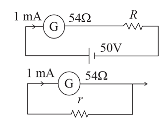
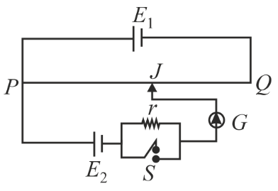
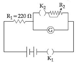
We have been told that the figure of merit of the galvanometer is $$k = 60\;\mu\text{A division}^{-1}$$. By definition,
$$I_g = k\,\theta$$
where $$I_g$$ is the current through the galvanometer and $$\theta$$ is the scale deflection in divisions. Substituting $$\theta = 9$$ divisions,
$$I_g = 60\;\mu\text{A}\times 9 = 540\;\mu\text{A}= 5.4\times10^{-4}\ \text{A}$$
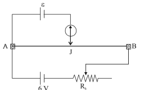
In the first observation (no shunt connected) the 6 V battery drives this current through the series combination of the high resistance $$R = 11\ \text{k}\Omega = 11000\ \Omega$$ and the unknown resistance $$G$$ of the galvanometer itself. Applying Ohm’s law,
$$V = I_g\,(R+G)$$
Substituting $$V = 6\ \text{V}$$ and $$I_g = 5.4\times10^{-4}\ \text{A}$$,
$$6 = 5.4\times10^{-4}\,(11000 + G)$$
$$\Rightarrow\; 11000 + G = \frac{6}{5.4\times10^{-4}}$$
$$\Rightarrow\; 11000 + G = 11111.11$$
$$\Rightarrow\; G = 11111.11 - 11000 = 111.11\ \Omega$$
So, the resistance of the galvanometer is approximately $$G \approx 111\ \Omega$$.
We now connect a shunt resistance $$S$$ in parallel with the galvanometer. We wish the new deflection to be $$\dfrac{\theta}{2}$$, i.e. the current through the galvanometer must fall to
$$I_g' = \frac{I_g}{2} = \frac{5.4\times10^{-4}}{2}= 2.7\times10^{-4}\ \text{A}$$
Let $$R_p$$ be the equivalent resistance of $$G$$ in parallel with $$S$$. The formula for two resistances in parallel is first stated:
$$R_p = \frac{G\,S}{G+S}$$
The total resistance in the circuit after the shunt is connected is $$R + R_p$$, so the total current delivered by the battery is
$$I = \frac{V}{R + R_p} = \frac{6}{11000 + R_p}$$
Current division tells us that the current through the galvanometer branch is
$$I_g' = I\;\frac{S}{G+S}$$
We require $$I_g' = 2.7\times10^{-4}\ \text{A}$$. Substituting all relations step by step,
$$2.7\times10^{-4} = \frac{6}{11000 + R_p}\;\frac{S}{G+S}$$
Because $$R_p = \dfrac{G\,S}{G+S}$$, we replace it and obtain one single equation containing only the unknown $$S$$:
$$2.7\times10^{-4} = \frac{6}{11000 + \dfrac{G\,S}{G+S}}\;\frac{S}{G+S}$$
To eliminate the fractions we multiply both sides by the two denominators:
$$\Bigl(2.7\times10^{-4}\Bigr)\Bigl(11000 + \dfrac{G\,S}{G+S}\Bigr)(G+S) = 6\,S$$
It is more convenient, however, to work with the ratio $$\dfrac{I_g'}{I_g}$$, because $$I_g'/I_g = 1/2$$ by design. Starting from
$$\frac{I_g'}{I_g} = \frac{V}{R+R_p}\;\frac{S}{G+S}\;\frac{R+G}{V}= \frac{R+G}{R+R_p}\;\frac{S}{G+S}$$
and demanding $$\dfrac{I_g'}{I_g}= \dfrac12$$, we write
$$\frac{1}{2} = \frac{R+G}{R+R_p}\;\frac{S}{G+S}$$
Now substitute the known numerical values $$R = 11000\ \Omega$$, $$G = 111.11\ \Omega$$ and $$R_p = \dfrac{G\,S}{G+S}$$:
$$\frac12 = \frac{11000+111.11}{11000+\dfrac{111.11\,S}{111.11+S}}\;\frac{S}{111.11+S}$$
The numerator $$R+G = 11000+111.11 = 11111.11$$, so a single explicit equation in $$S$$ is obtained:
$$\frac12 = \frac{11111.11}{11000+\dfrac{111.11\,S}{111.11+S}}\;\frac{S}{111.11+S}$$
Multiply both sides by the denominators to clear the fractions. First multiply by 2, then by the two bracketed terms:
$$2\times 11111.11\,S = \Bigl(11000+\dfrac{111.11\,S}{111.11+S}\Bigr)\,(111.11+S)$$
Compute the left-hand side:
$$2\times11111.11\,S = 22222.22\,S$$
For the right-hand side we distribute carefully:
$$\Bigl(11000+\dfrac{111.11\,S}{111.11+S}\Bigr)\,(111.11+S)=11000(111.11+S)+111.11\,S$$
Now insert this in the equality:
$$22222.22\,S = 11000(111.11+S)+111.11\,S$$
Expand the product containing 11000:
$$11000\times111.11 = 1222210$$
and
$$11000\times S = 11000\,S$$
so that the right-hand side becomes
$$1222210 + 11000\,S + 111.11\,S = 1222210 + 11111.11\,S$$
Our equation is now purely linear in $$S$$:
$$22222.22\,S = 1222210 + 11111.11\,S$$
Bring the term $$11111.11\,S$$ to the left to collect like terms:
$$(22222.22 - 11111.11)\,S = 1222210$$
$$11111.11\,S = 1222210$$
Finally divide to obtain $$S$$:
$$S = \frac{1222210}{11111.11} \approx 110\ \Omega$$
The answer that is the closest to this calculated value is 110 $$\Omega$$.
Hence, the correct answer is Option D.
A 9 V battery with an internal resistance of 0.5 $$\Omega$$ is connected across an infinite network, as shown in the figure. All ammeters $$A_1$$, $$A_2$$, $$A_3$$ and voltmeter $$V$$ are ideal. Choose the correct statement.
Let the total resistance of the network be R.
Since the network is infinite, the resistance of the network connected in parallel to the branch with ammeter $$A_2$$ is also R.
Thus, $$R=1+1+\frac{4\cdot R}{4+R}$$
$$R=2+\frac{4R}{4+R}$$
$$4R+R^2=8+6R$$
$$R^2-2R-8=0$$
$$\left(R-4\right)\left(R+2\right)=0$$
$$\therefore\ R=4Ω$$
Current passing through ammeter $$A_1$$ = Total current in the circuit = $$\frac{E}{R+0.5}$$
$$\therefore\ I_{A_1}=\frac{9}{4+0.5}=2A$$
Reading of $$V$$, $$V=E-I\cdot0.5=9-2\cdot0.5=8V$$
In the given circuit diagram, when the current reaches a steady-state in the circuit, the charge on the capacitor of capacitance $$C$$ will be:
In a DC circuit, once the capacitor reaches its steady-state (is fully charged), it acts as an open circuit. This means that no current flows through the branch containing the capacitor $$C$$ and the resistor $$r_1$$. Consequently, the potential drop across $$r_1$$ is zero ($$V_{r_1} = I \times r_1 = 0 \times r_1 = 0$$).
Using Ohm's Law, the steady-state current $$I = \frac{E}{r + r_2}$$
The potential difference across $$r_2$$ is $$V_{r_2} = I \times r_2$$
$$V_{r_2} = \left( \frac{E}{r + r_2} \right) \times r_2 = \frac{E r_2}{r + r_2}$$
Since $$V_C = V_{r_2}$$ (steady state), $$V_C = \frac{E r_2}{r + r_2}$$
$$Q = C \times V$$
$$Q = C \times \left( \frac{E r_2}{r + r_2} \right)$$
$$Q = CE \frac{r_2}{r + r_2}$$
A potentiometer $$PQ$$ is set up to compare two resistances, as shown in the figure. The ammeter $$A$$ in the circuit reads 1.0 A when the two-way key $$K_3$$ is open. The balance point is at a length $$l_1$$ cm from $$P$$ when the two-way key $$K_3$$ is plugged in between 2 and 1, while the balance point is at a length $$l_2$$ cm from $$P$$ when the key $$K_3$$ is plugged in between 3 and 1. The ratio of two resistances $$\frac{R_1}{R_2}$$, is found to be:
When key $$K_3$$ is plugged between 2 and 1, the galvanometer compares the potential difference across the resistance $$R_1$$
Let the balance length be $$l_1$$. Then,
$$V_1\ ∝\ l_1$$ & $$V_1\ ∝\ R_1$$
When key $$K_3$$ is plugged between 3 and 1, now the galvanometer compares the potential difference across the combination of $$R_1$$ & $$R_2$$.
Let the balance length be $$l_2$$. Then,
$$V_2\ ∝\ l_2$$ & $$V_2\ ∝\ R_1+R_2$$
$$\frac{V_1}{V_2}=\frac{R_1}{R_1+R_2}=\frac{l_1}{l_2}$$
$$R_1l_2=\left(R_1+R_2\right)l_1$$
$$R_1\left(l_2-l_1\right)=R_2l_1$$
$$\therefore\ \frac{R_1}{R_2}=\frac{l_1}{l_2-l_1}$$
In a meter bridge experiment resistances are connected as shown in the figure. Initially resistance $$P = 4 \; \Omega$$ and the neutral point $$N$$ is at 60 cm from $$A$$. Now an unknown resistance $$R$$ is connected in series to $$P$$ and the new position of the neutral point is at 80 cm from $$A$$. The value of unknown resistance $$R$$ is -
We recall that the meter bridge works on the principle of the Wheatstone bridge. For a balanced bridge, the ratio of the resistances in the two gaps is equal to the ratio of the corresponding lengths of the wire, that is
$$\frac{\text{Resistance in left gap}}{\text{Resistance in right gap}} \;=\; \frac{\text{Length of wire from }A\text{ to }N} {\text{Length of wire from }N\text{ to the other end}}.$$
Initially only the resistance $$P$$ is placed in the left gap, while an unknown resistance, which we will call $$Q$$, is present in the right gap. We are told that $$P = 4 \;\Omega$$ and that the neutral point $$N$$ is found at 60 cm from end $$A$$. The total length of the wire is 100 cm, so the right-side length is
$$100\;\text{cm} - 60\;\text{cm} = 40\;\text{cm}.$$
Applying the Wheatstone‐bridge relation we have
$$\frac{P}{Q} = \frac{60}{40}.$$
Substituting $$P = 4\;\Omega$$ gives
$$\frac{4}{Q} = \frac{60}{40}.$$
First reduce the numerical fraction on the right:
$$\frac{60}{40} = \frac{3}{2}.$$
So
$$\frac{4}{Q} = \frac{3}{2}.$$
Cross-multiplying,
$$4 \times 2 = 3 \times Q,$$
$$8 = 3Q,$$
$$Q = \frac{8}{3}\;\Omega.$$
Now an additional resistance $$R$$ is connected in series with $$P$$, so the total resistance in the left gap becomes $$P + R$$. In the new situation the balance point shifts to 80 cm from end $$A$$. Hence the left-side length is 80 cm and the right-side length is
$$100\;\text{cm} - 80\;\text{cm} = 20\;\text{cm}.$$
Applying the Wheatstone relation again, we now write
$$\frac{P + R}{Q} = \frac{80}{20}.$$
Simplify the fraction on the right:
$$\frac{80}{20} = 4.$$
Therefore,
$$\frac{P + R}{Q} = 4.$$
Cross-multiplying gives
$$(P + R) = 4Q.$$
Substituting the known values $$P = 4\;\Omega$$ and $$Q = \dfrac{8}{3}\;\Omega$$, we get
$$4 + R = 4 \left(\frac{8}{3}\right).$$
Compute the right-hand side:
$$4 \left(\frac{8}{3}\right) = \frac{32}{3}\;\Omega.$$
Hence
$$4 + R = \frac{32}{3}.$$
To isolate $$R$$ subtract 4 Ω (that is, $$\dfrac{12}{3}\;\Omega$$) from both sides:
$$R = \frac{32}{3} - \frac{12}{3} = \frac{20}{3}\;\Omega.$$
This simplifies numerically to approximately 6.67 Ω, but the exact fractional form is already one of the options.
Hence, the correct answer is Option C.
In the above circuit the current in each resistance is:
Let the potential at the bottom-left node be $$0\text{V}$$.
1. Potentials Along the Bottom Rail
The first battery ($$2\text{V}$$) is encountered with the positive terminal on the right. Potential at the bottom of the first resistor = $$0\text{V} + 2\text{V} = 2\text{V}$$.
The second battery further increases the potential. Potential at the bottom of the second resistor = $$2 + 2 = 4\text{V}$$.
The third battery further increases the potential. Potential at the bottom of the third resistor = $$4\text{V} + 2\text{V} = 6\text{V}$$.
2. Potentials Along the Top Rail
The first battery ($$2\text{V}$$) is encountered with the positive terminal on the right. Potential at the top of the first resistor = $$0\text{V} + 2\text{V} = 2\text{V}$$.
The second battery ($$2\text{V}$$) follows. Potential at the top of the second resistor = $$2\text{V} + 2\text{V} = 4\text{V}$$.
The third battery ($$2\text{V}$$) follows. Potential at the top of the third resistor = $$4\text{V} + 2\text{V} = 6\text{V}$$.
3. Current in each resistor:
Resistor 1: $$\Delta V = V_{top} - V_{bottom} = 2\text{V} - 2\text{V} = 0\text{V} \implies I_1 = 0\text{A}$$
Resistor 2: $$\Delta V = V_{top} - V_{bottom} = 4\text{V} - 4\text{V} = 0\text{V} \implies I_2 = 0\text{A}$$
Resistor 3: $$\Delta V = V_{top} - V_{bottom} = 6\text{V} - 6\text{V} = 0\text{V} \implies I_3 = 0\text{A}$$
Which of the following statements is false?
We begin by examining each of the four statements one by one and verifying whether it is in accordance with the well-known principles of electric circuits.
First consider Option A. Kirchhoff’s second law, also called the loop law, states that in any closed conducting loop the algebraic sum of all the electromotive forces and the potential drops is zero. Mathematically we write
$$\sum E + \sum IR = 0,$$
where $$E$$ denotes the electromotive forces in the loop and $$IR$$ represents the potential drops across resistive elements. This equation is merely an application of the law of conservation of energy, because the total energy gained by the charges from the sources equals the total energy lost across the resistances in one complete traversal of the loop. Hence Option A is a true statement.
Now look at Option B. The sensitivity of a Wheatstone bridge is defined as the deflection shown by the galvanometer per unit fractional change in one of the resistances. By theory, the sensitivity turns out to be the highest when the four resistances in the bridge are of the same order of magnitude, that is, when
$$R_1 \approx R_2 \approx R_3 \approx R_4.$$
This is because equal arms give the largest change in galvanometer current for a given small fractional change in resistance, making the bridge highly responsive. Therefore Option B is also true.
Next examine Option C. In a Wheatstone bridge the balance condition is
$$\frac{R_1}{R_2} = \frac{R_3}{R_4}.$$
If this ratio is satisfied, the potential difference between the two mid-points (to which the galvanometer is connected) is zero, so no current flows through the galvanometer and the bridge is said to be balanced (null condition). Now suppose the cell and the galvanometer are interchanged. The resistive network remains exactly the same, and the points that were at equal potential earlier are still at equal potential because the above ratio remains unaltered. Hence the null point is not disturbed; the bridge stays balanced. The statement in Option C says that the null point is disturbed, which contradicts the actual behavior. Consequently, Option C is false.
Finally consider Option D. A rheostat is simply a variable resistor. By tapping a fraction of the total resistance, one can obtain an adjustable potential difference across a portion of the resistor while the rest of the resistor drops the remaining voltage. This arrangement is popularly known as a potential divider. Because a rheostat performs exactly this function, Option D is indeed correct.
Summarising our findings: Options A, B and D are true, whereas Option C is not. Hence, the statement that is false is the one given in Option C, which corresponds to choice number 3 in the list.
Hence, the correct answer is Option C.
The figure shows three circuits I, II and III which are connected to a 3 V battery. If the powers dissipated by the configurations I, II and III are $$P_1$$, $$P_2$$ and $$P_3$$ respectively, then -
The configuration (I) is a balanced wheatstone bridge with an effective resistance of $$R_{e1}=\frac{\left(1+1\right)\cdot\left(1+1\right)}{\left(1+1\right)+\left(1+1\right)}=\frac{4}{4}=1Ω$$
Power, $$P_1=\frac{V^2}{R_{e1}}=\frac{9}{1}=9\ W$$
Effective resistance of configuration (II) is $$R_{e2}=\frac{1\cdot1}{1+1}=0.5Ω$$
Power, $$P_2=\frac{V^2}{R_{e2}}=\frac{9}{0.5}=18\ W$$
Effective resistance of configuration (III) is $$R_{e3}=1+\frac{2\cdot2}{2+2}=2Ω$$
Power, $$P_3=\frac{V^2}{R_{e3}}=\frac{9}{2}=4.5\ W$$
$$\therefore\ $$ $$P_2>P_1>P_3$$
In the circuit shown, the resistance r is a variable resistance. If for $$r = fR$$, the heat generation in r is maximum then the value of f is
$$R_{total} = R + \frac{Rr}{R+r} = \frac{R^2 + Rr + Rr}{R + r} = \frac{R^2 + 2Rr}{R + r}$$
$$I = \frac{V}{R_{total}} = \frac{V(R + r)}{R^2 + 2Rr}$$
$$I_r = I \times \left( \frac{R}{R + r} \right)$$
$$I_r = \left( \frac{V(R + r)}{R^2 + 2Rr} \right) \times \frac{R}{R + r} = \frac{VR}{R^2 + 2Rr}$$
$$P = I_r^2 \cdot r$$: $$P = \left( \frac{VR}{R^2 + 2Rr} \right)^2 \cdot r$$
$$P = \frac{V^2 R^2 r}{(R^2 + 2Rr)^2}$$
$$P = \frac{V^2 R^2}{\frac{R^4}{r} + 4R^2r + 4R^3}$$
For $$P$$ to be maximum, the denominator $$D = \left( \frac{R^4}{r} + 4R^2r + 4R^3 \right)$$ must be minimum.
Using the AM-GM inequality, a sum of the form $$\frac{a}{x} + bx$$ is minimum when the two terms are equal:
$$\frac{R^4}{r} = 4R^2r$$
$$R^2 = 4r^2$$
$$R = 2r \implies r = \frac{R}{2}$$
$$f = \frac{1}{2}$$
In the given circuits (a) and (b), switches $$S_1$$ and $$S_2$$ are closed at $$t = 0$$ and kept close for a long time. The variation of currents in the two circuits for $$t \geq 0$$ are shown in the options. (Figures are schematic and not drawn to scale.)
1. Analysis of Circuit (a): RC Series Circuit
In an RC circuit, when the switch $$S_1$$ is closed at $$t=0$$:
The current decays exponentially according to the equation: $$i_a(t) = \frac{E}{R} e^{-\frac{t}{RC}}$$
Curve must start at $$i = \frac{E}{R}$$ and approach $$0$$ as $$t$$ increases.
2. Analysis of Circuit (b): RL Series Circuit
In an RL circuit, when the switch $$S_2$$ is closed at $$t=0$$:
The current grows exponentially towards its steady-state value according to the equation: $$i_b(t) = \frac{E}{R} \left(1 - e^{-\frac{Rt}{L}}\right)$$
Curve must start at $$i = 0$$ and approach $$\frac{E}{R}$$ as $$t$$ increases.
Option (B) correctly depicts curve (a) as a decaying exponential starting from $$\frac{E}{R}$$ and curve (b) as a rising exponential approaching the steady-state value $$\frac{E}{R}$$
A 10 V battery with internal resistance 1 $$\Omega$$ and a 15 V battery with internal resistance 0.6 $$\Omega$$ are connected in parallel to a voltmeter (see figure). The reading in the voltmeter will be close to:
The formula for the equivalent EMF of two cells connected in parallel (with the same polarity) is:
$$E_{eq} = \frac{E_1 r_2 + E_2 r_1}{r_1 + r_2}$$
$$E_{eq} = \frac{\frac{E_1}{r_1} + \frac{E_2}{r_2}}{\frac{1}{r_1} + \frac{1}{r_2}}$$
$$E_1 r_2 = 10 \times 0.6 = 6$$, $$E_2 r_1 = 15 \times 1 = 15$$, $$r_1 + r_2 = 1 + 0.6 = 1.6$$
$$E_{eq} = \frac{6 + 15}{1.6}$$
$$E_{eq} = \frac{21}{1.6}$$
$$E_{eq} = 13.125 \text{ V}$$
In the circuit shown, the current in the 1 $$\Omega$$ resistor is:
Connect the lower wire of the $$1\ \Omega$$ resistor to the ground ($$Q$$ end) and apply KCL at node $$P$$.
$$\frac{V + 6}{3} + \frac{V}{1} + \frac{V - 9}{5} = 0$$
$$\Rightarrow V \left[ \frac{1}{3} + 1 + \frac{1}{5} \right] = \frac{9}{5} - \frac{6}{3}$$
$$\Rightarrow V \left[ \frac{5 + 15 + 3}{15} \right] = \frac{9 - 10}{5}$$
$$\Rightarrow V \left[ \frac{23}{15} \right] = -\frac{1}{5}$$
$$\Rightarrow V = -\frac{1}{5} \times \frac{15}{23} = \frac{-3}{23} = -0.13\text{ V}$$
Thus, the magnitude of current in the $$1\ \Omega$$ resistor is $$I = \frac{|V|}{R} = \frac{0.13}{1} = 0.13\text{ A}$$
Since the potential at $$P$$ is negative relative to $$Q$$, the current flows from $$Q$$ to $$P$$.
In the electric network shown, when no current flows through the 4 $$\Omega$$ resistor in the arm EB, the potential difference between the points A and D will be:
$$V_E = V_B + 4 - (I_{EB} \times 4)$$
$$I_{EB} = 0$$
$$V_E = V_B + 4\ \text{V}$$
$$V_A - V_B = 9\ \text{V} \implies V_B = V_A - 9\ \text{V}$$
$$V_D = V_E$$
$$V_E = (V_A - 9\ \text{V}) + 4\ \text{V}$$
$$V_E = V_A - 5\ \text{V}$$
$$V_A - V_E = 5\ \text{V}$$
Since $$V_E = V_D$$, $$V_A - V_D = 5\ \text{V}$$
A d.c. main supply of e.m.f. 220 V is connected across a storage battery of e.m.f. 200 V through a resistance of 1 $$\Omega$$. The battery terminals are connected to external resistance $$R$$. The minimum value of $$R$$, so that a current passes through the battery to charge it is:
The circuit consists of a DC main supply of 220 V connected across a storage battery of 200 V through a 1 Ω resistance. The battery terminals are also connected to an external resistance $$R$$. We need to find the minimum value of $$R$$ such that current flows through the battery to charge it, meaning current enters the positive terminal of the battery.
First, we assume the battery has no internal resistance, as it is not specified in the problem. Therefore, the voltage across the battery terminals is always equal to its EMF, which is 200 V. Let the common negative terminal be point C, and the positive terminal of the supply be point A. The supply is connected to a 1 Ω resistor, and the other end of this resistor is connected to the positive terminal of the battery (point B) and one end of $$R$$. The negative terminal of the battery and the other end of $$R$$ are connected to point C.
Since the voltage at point B with respect to point C is the same as the battery voltage, $$V_{BC} = 200$$ V. The supply voltage is 220 V between A and C, so $$V_{AC} = 220$$ V. The voltage drop across the 1 Ω resistor (between A and B) is $$V_{AB} = V_{AC} - V_{BC} = 220 - 200 = 20$$ V.
The current through the 1 Ω resistor, flowing from A to B, is given by Ohm's law: $$I = \frac{V_{AB}}{1 \Omega} = \frac{20}{1} = 20$$ A.
At junction B, this current $$I$$ splits into two parts: $$I_b$$ through the battery and $$I_R$$ through the external resistance $$R$$. Applying Kirchhoff's current law: $$I = I_b + I_R$$, so $$20 = I_b + I_R$$.
The voltage across $$R$$ is the same as $$V_{BC} = 200$$ V, so by Ohm's law, $$I_R = \frac{V_{BC}}{R} = \frac{200}{R}$$. Substituting this in: $$20 = I_b + \frac{200}{R}$$.
For the battery to charge, current must enter its positive terminal, so $$I_b > 0$$. Therefore, $$20 - \frac{200}{R} > 0$$. Solving this inequality:
$$20 > \frac{200}{R}$$
Since $$R$$ is positive, multiply both sides by $$R$$: $$20R > 200$$.
Divide both sides by 20: $$R > 10 \Omega$$.
Thus, $$R$$ must be greater than 10 Ω for charging to occur. The minimum value of $$R$$ in the given options that satisfies this condition is 11 Ω.
Hence, the correct answer is Option C.
In the circuit shown, current (in A) through 50 V and 30 V batteries are, respectively:
$$I_{20\Omega} = \frac{50\text{ V}}{20\ \Omega} = 2.5\text{ A (downward)}$$
$$I_{10\Omega} = \frac{30\text{ V}}{10\ \Omega} = 3\text{ A (downward)}$$
$$I_{horizontal} = \frac{50 - 30}{5 + 5} = \frac{20}{10} = 2\text{ A (left to right)}$$
$$I_{50V} = I_{20\Omega} + I_{horizontal} = 2.5\text{ A} + 2\text{ A} = 4.5\text{ A}$$
$$2\text{ A} + I_{30V} = 3\text{ A} \implies I_{30V} = 1\text{ A}$$
The circuit shown here has two batteries of 8.0 V and 16.0 V and three resistors 3$$\Omega$$, 9$$\Omega$$ and 9$$\Omega$$ and a capacitor of 5.0 $$\mu$$F. How much is the current I in the circuit in steady state?
The two batteries are connected in opposition. The net electromotive force ($$\text{EMF}$$) of the loop is $$\epsilon_{\text{net}} = 16.0\text{ V} - 8.0\text{ V} = 8.0\text{ V}$$
$$R_{\text{total}} = 3\ \Omega + 9\ \Omega = 12\ \Omega$$ (in steady state)
$$I = \frac{\epsilon_{\text{net}}}{R_{\text{total}}}$$
$$I = \frac{8.0}{12}$$
$$I = \frac{2}{3}\text{ A} \approx 0.67\text{ A}$$
In an LCR circuit shown below, both the switches are open initially. Now switch $$S_1$$ is closed, $$S_2$$ kept open. (q is charge on the capacitor and $$\tau$$ = RC is capacitive time constant). Which of the following statement is correct?
The charge $$q$$ on the capacitor at any time $$t$$ is given by the charging equation $$q(t) = CV(1 - e^{-t/\tau})$$, where $$\tau = RC$$ is the capacitive time constant.
Option A: At $$t = 2\tau$$: $$q = CV(1 - e^{-2\tau/\tau}) = CV(1 - e^{-2})$$
Option B: At $$t = \frac{\tau}{2}$$: $$q = CV(1 - e^{-(\tau/2)/\tau}) = CV(1 - e^{-1/2})$$
Option C: For a capacitor charging to its maximum, the work done by the battery is $$W = CV^2$$. The energy stored in the capacitor is $$U = \frac{1}{2}CV^2$$, and the energy dissipated in the resistor is also $$E_R = \frac{1}{2}CV^2$$. Therefore, the work done by the battery is twice the energy dissipated.
Option D: At $$t = \tau$$: $$q = CV(1 - e^{-1}) \approx 0.63 CV$$
A dc source of emf $$E_1 = 100$$ V and internal resistance $$r = 0.5\Omega$$, a storage battery of emf $$E_2 = 90$$ V and an external resistance R are connected as shown in figure. For what value of R no current will pass through the battery?
We are given a DC source with emf $$ E_1 = 100 $$ V and internal resistance $$ r = 0.5 \, \Omega $$, a storage battery with emf $$ E_2 = 90 $$ V, and an external resistance $$ R $$. The goal is to find the value of $$ R $$ such that no current passes through the battery. This means the battery $$ E_2 $$ is effectively inactive, and the voltage across its terminals must equal its emf, $$ 90 $$ V.
In the circuit, the DC source $$ E_1 $$ with internal resistance $$ r $$ is connected in series with the external resistance $$ R $$. The battery $$ E_2 $$ is connected in parallel with $$ R $$. Therefore, the voltage across $$ R $$ must equal $$ E_2 $$ for no current to flow through the battery. So, we set the voltage across $$ R $$ equal to $$ 90 $$ V.
The total resistance in the series circuit is $$ r + R = 0.5 + R $$ ohms. The current $$ I $$ flowing through the circuit is given by Ohm's law:
$$ I = \frac{E_1}{r + R} = \frac{100}{0.5 + R} $$
The voltage across $$ R $$ is $$ V_R = I \times R $$. Setting this equal to $$ E_2 $$:
$$ V_R = \frac{100}{0.5 + R} \times R = 90 $$
Now, solve for $$ R $$:
$$ \frac{100R}{0.5 + R} = 90 $$
Multiply both sides by $$ 0.5 + R $$:
$$ 100R = 90 \times (0.5 + R) $$
Calculate $$ 90 \times 0.5 = 45 $$:
$$ 100R = 45 + 90R $$
Subtract $$ 90R $$ from both sides:
$$ 100R - 90R = 45 $$
$$ 10R = 45 $$
Divide both sides by 10:
$$ R = \frac{45}{10} = 4.5 \, \Omega $$
Thus, when $$ R = 4.5 \, \Omega $$, no current flows through the battery. Comparing with the options:
A. $$ 5.5 \, \Omega $$
B. $$ 3.5 \, \Omega $$
C. $$ 4.5 \, \Omega $$
D. $$ 2.5 \, \Omega $$
Hence, the correct answer is Option C.
Which of the four resistances P, Q, R and S generate the greatest amount of heat when a current flows from A to B?
Because these branches are in parallel, the branch with lower resistance draws more current. Since the bottom branch ($$3\Omega$$) has half the resistance of the top branch ($$6\Omega$$), it carries double the current. Let the top current be $$I$$ and the bottom current be $$2I$$.
Heat generated:
P ($$2\Omega$$): $$I^2 \times 2 = 2I^2$$
Q ($$4\Omega$$): $$4I^2 \times 4 = 4I^2$$
R ($$1\Omega$$): $$(2I)^2 \times 1 = 4I^2$$
S ($$2\Omega$$): $$(2I)^2 \times 2 = \mathbf{8I^2}$$
Correct set up to verify Ohm's law is :
In option A, the voltmeter is connected directly in parallel across the target resistor, and the ammeter is connected in series within the main path carrying the loop current. This ensures correct simultaneous readings of voltage and current. Hence, it is the correct setup.
A generator has armature resistance of $$0.1\Omega$$ and develops an induced emf of $$120$$ V when driven at its rated speed. Its terminal voltage when a current of $$50$$ A is being drawn is
In an experiment of potentiometer for measuring the internal resistance of primary cell a balancing length $$\ell$$ is obtained on the potentiometer wire when the cell is open circuit. Now the cell is short circuited by a resistance $$R$$. If $$R$$ is to be equal to the internal resistance of the cell the balancing length on the potentiometer wire will be
A resistance $$R$$ and a capacitance $$C$$ are connected in series to a battery of negligible internal resistance through a key. The key is closed at $$t = 0$$. If after $$t$$ sec the voltage across the capacitance was seven times the voltage across $$R$$, the value of $$t$$ is
A resistor $$R$$ and $$2 \mu \text{F}$$ capacitor in series is connected through a switch to $$200 \, \text{V}$$ direct supply. Across the capacitor is a neon bulb that lights up at $$120 \, \text{V}$$. Calculate the value of $$R$$ to make the bulb light up $$5 \, \text{s}$$ after the switch has been closed. ($$\log_{10} 2.5 = 0.4$$)
A 5 V battery with internal resistance $$2\Omega$$ and a 2 V battery with internal resistance $$1\Omega$$ are connected to a $$10\Omega$$ resistor as shown in the figure. The current in the $$10\Omega$$ resistor is
The Kirchhoff's first law $$\left(\sum i = 0\right)$$ and second law $$\left(\sum iR = \sum E\right)$$, where the symbols have their usual meanings, are respectively based on
In a Wheatstone's bridge, there resistances $$P, Q$$ and $$R$$ connected in the three arms and the fourth arm is formed by two resistances $$S_1$$ and $$S_2$$ connected in parallel. The condition for bridge to be balanced will be
Consider the circuit shown below. The current $$I$$ drawn from the 5 volt source will be
In the circuit, the galvanometer $$G$$ shows zero deflection. If the batteries $$A$$ and $$B$$ have negligible resistance, the value of the resistor $$R$$ will be 
Two sources of equal emf are connected to an external resistance $$R$$. The internal resistance of the two sources are $$R_1$$ and $$R_2$$ ($$R_2 > R_1$$). If the potential difference across the source having internal resistance $$R_2$$ is zero, then
An energy source will supply a constant current into the load if its internal resistance is
In a potentiometer experiment the balancing with a cell is at length $$240$$ cm. On shunting the cell with a resistance of $$2 \Omega$$ the balancing length becomes $$120$$ cm. The internal resistance of the cell is
The total current supplied to the circuit by the battery is