The electrostatic potential in a charged spherical region of radius r varies as $$V=ar^{3}+b$$, where a and b are constants. The total charge in the sphere of unit radius is $$\alpha \times \pi a\in_{\circ}$$. the value of $$\alpha$$ is_____. (permittivity of vacuum is $$\in_{\circ}$$)
JEE Electric Potential & Capacitance Questions
Potential in a spherical region is given by $$V = ar^3 + b$$. We seek the total charge enclosed in a sphere of unit radius.
Since the electric field is related to the potential by $$E = -\frac{dV}{dr}$$, it follows that $$E = -3ar^2$$. The negative sign indicates the field points inward when $$a>0$$.
Using Gauss’s law for a sphere of radius $$r$$, we have $$\oint \vec{E}\cdot d\vec{A} = \frac{Q_{\text{enc}}}{\varepsilon_0}$$, which simplifies to $$E\cdot 4\pi r^2 = \frac{Q}{\varepsilon_0}$$. At $$r = 1$$, the field becomes $$E = -3a$$ (with magnitude $$|E| = 3|a|$$, directed radially). Substituting these values gives $$(-3a)\,(4\pi)\,(1)^2 = \frac{Q}{\varepsilon_0}$$, and hence $$Q = -12\pi a\varepsilon_0$$.
Comparing this result with the form $$Q = \alpha \pi a \varepsilon_0$$ shows that $$\alpha = -12$$.
The correct answer is Option (3): $$-12$$.
Electric field in a region is given by $$\overrightarrow{E}=Ax\widehat{i}+By\widehat {j}$$, where $$A= 10V/m^{2}$$, and $$B= 5V/m^{2}$$. If the electric potential at a point (10, 20) is 500 $$V$$, then the electric potential at origin is____ $$V$$.
We use the relation between electric field and potential: $$\overrightarrow{E} = -\nabla V\,. $$ For a two-dimensional field $$\overrightarrow{E}=E_x\,\widehat{i}+E_y\,\widehat{j}$$, this gives
$$E_x = -\frac{\partial V}{\partial x},\quad E_y = -\frac{\partial V}{\partial y}\,.$$
Given $$E_x = A\,x$$ and $$E_y = B\,y$$, we write:
$$-\frac{\partial V}{\partial x} = A\,x\quad\Longrightarrow\quad \frac{\partial V}{\partial x} = -A\,x \quad -(1)$$
Integrate $$(1)$$ with respect to $$x$$ (treating $$y$$ as constant):
$$V(x,y) = -A\int x\,dx + f(y) = -\frac{A\,x^2}{2} + f(y)\quad -(2)$$
Similarly, from $$E_y$$:
$$-\frac{\partial V}{\partial y} = B\,y\quad\Longrightarrow\quad \frac{\partial V}{\partial y} = -B\,y \quad -(3)$$
Differentiate expression $$(2)$$ with respect to $$y$$:
$$\frac{\partial V}{\partial y} = \frac{d}{dy}\Bigl(-\frac{A\,x^2}{2} + f(y)\Bigr) = f'(y)\quad -(4)$$
Equate $$(3)$$ and $$(4)$$:
$$f'(y) = -B\,y$$
Integrate with respect to $$y$$:
$$f(y) = -B\int y\,dy + C = -\frac{B\,y^2}{2} + C\quad -(5)$$
Substitute $$(5)$$ into $$(2)$$ to obtain the general potential:
$$V(x,y) = -\frac{A\,x^2}{2} - \frac{B\,y^2}{2} + C\quad -(6)$$
Use the condition $$V(10,20)=500\,$$V in $$(6)$$:
$$500 = -\frac{A\,(10)^2}{2} - \frac{B\,(20)^2}{2} + C\,. $$
Substitute $$A=10\,$$V/m2 and $$B=5\,$$V/m2:
$$500 = -\frac{10\times100}{2} - \frac{5\times400}{2} + C = -500 -1000 + C\,. $$
Thus,
$$C = 500 + 1500 = 2000\quad -(7)$$
The potential at the origin $$(0,0)$$ is:
$$V(0,0) = -\frac{A\cdot0^2}{2} - \frac{B\cdot0^2}{2} + C = C = 2000\;\text{V}\,.$$
Answer: 2000
Identify the correct statements:
A. Effective capacitance of a series combination of capacitors is always smaller than the smallest capacitance of the capacitor in the combination.
B. When a dielectric mediwn is placed between the charged plates of a capacitor, displacement of charges cannot occurdue to insulation property of dielectric.
C. Increasing of area of capacitor plate or decreasing of thickness of dielectric is an alternate method to increase the capacitance.
D. For a point charge, concentric spherical shells centered at the location of the charge are equipotential surfaces.
Choose the correct answer from the options given below :
We need to identify which statements about capacitors and related concepts are correct.
Statement A: "Effective capacitance of a series combination is always smaller than the smallest capacitance."
For series: $$\frac{1}{C_{eq}} = \frac{1}{C_1} + \frac{1}{C_2} + \cdots > \frac{1}{C_{\min}}$$
Therefore $$C_{eq} < C_{\min}$$. This is TRUE.
Statement B: "When a dielectric is placed between charged plates, displacement of charges cannot occur due to insulation property."
This is FALSE. Even though a dielectric is an insulator, the electric field causes polarization - slight displacement of bound charges within molecules, creating induced surface charges. This is how dielectrics reduce the effective field.
Statement C: "Increasing area or decreasing thickness of dielectric increases capacitance."
$$C = \frac{\epsilon_0 \epsilon_r A}{d}$$. Increasing $$A$$ or decreasing $$d$$ increases $$C$$. This is TRUE.
Statement D: "For a point charge, concentric spherical shells centered at the charge are equipotential surfaces."
The potential due to a point charge is $$V = \frac{kq}{r}$$, which depends only on $$r$$. All points at the same distance from the charge have the same potential. This is TRUE.
Conclusion: Statements A, C, and D are correct.
The correct answer is Option 4: A, C and D Only.
A parallel plate air capacitor has a capacitance C. When it is half filled as shown in figure with a dielectric constant $$K = 5$$, the percentage increase in the capacitance is __________.
Let the plates have area $$A$$ and separation $$d$$.
For air between the plates the capacitance is
$$C=\frac{\varepsilon_0 A}{d} \quad -(1)$$
The dielectric slab of constant $$K=5$$ completely occupies one-half of the gap (thickness $$d/2$$).
Hence the space between the plates now behaves like two capacitors in series:
Case 1: Region filled with dielectric
Thickness $$=\frac{d}{2}$$, permittivity $$=\varepsilon_0 K$$
$$C_1=\frac{\varepsilon_0 K A}{d/2}=2K\,\frac{\varepsilon_0 A}{d}=2K\,C \quad -(2)$$
Case 2: Region still filled with air
Thickness $$=\frac{d}{2}$$, permittivity $$=\varepsilon_0$$
$$C_2=\frac{\varepsilon_0 A}{d/2}=2\,\frac{\varepsilon_0 A}{d}=2\,C \quad -(3)$$
For capacitors in series:
$$\frac{1}{C'}=\frac{1}{C_1}+\frac{1}{C_2}$$
Substituting from $$(2)$$ and $$(3)$$:
$$\frac{1}{C'}=\frac{1}{2K\,C}+\frac{1}{2\,C}=\frac{1+K}{2K\,C}$$
$$\Rightarrow\; C'=\frac{2K\,C}{1+K} \quad -(4)$$
For $$K=5$$:
$$C'=\frac{2\times5\,C}{1+5}=\frac{10\,C}{6}=\frac{5}{3}C\approx1.6667\,C$$
Percentage increase in capacitance:
$$\%\text{ increase}= \frac{C'-C}{C}\times100 =\left(\frac{5}{3}-1\right)\times100=\frac{2}{3}\times100=66.67\%$$
Therefore, the capacitance increases by $$66.67\%$$.
Option B which is: $$66.67$$
A parallel plate capacitor has capacitance C, when there is vacuum within the parallel plates. A sheet having thickness $$\left(\frac{1}{3}\right)^{rd}$$ of the separation between the plates and relative permittivity K is introduced between the plates. The new capacitance of the system is:
A parallel plate capacitor of capacitance $$C$$ in vacuum, with plate area $$A$$ and plate separation $$d$$, has a dielectric sheet of thickness $$\frac{d}{3}$$ and relative permittivity $$K$$ introduced between the plates. To determine the new capacitance $$C'$$, we first recall the original expression for a vacuum-filled parallel plate capacitor: $$C = \frac{\epsilon_0 A}{d}$$.
After inserting the dielectric, the system can be modeled as two capacitors in series. The region containing the dielectric has thickness $$t = \frac{d}{3}$$ and permittivity $$K\epsilon_0$$, leading to $$C_1 = \frac{K\epsilon_0 A}{d/3} = \frac{3K\epsilon_0 A}{d}\,. $$ The remaining vacuum region has thickness $$\frac{2d}{3}$$ and permittivity $$\epsilon_0$$, giving $$C_2 = \frac{\epsilon_0 A}{2d/3} = \frac{3\epsilon_0 A}{2d}\,. $$
For capacitors in series, $$\frac{1}{C'} = \frac{1}{C_1} + \frac{1}{C_2}\,. $$ Substituting the expressions for $$C_1$$ and $$C_2$$ yields $$\frac{1}{C'} = \frac{d}{3K\epsilon_0 A} + \frac{2d}{3\epsilon_0 A} = \frac{d}{3\epsilon_0 A}\Bigl(\frac{1}{K} + 2\Bigr) = \frac{d}{3\epsilon_0 A}\,\frac{1 + 2K}{K}\,. $$
Inverting this result gives $$C' = \frac{3K\epsilon_0 A}{d(2K + 1)}\,. $$ Since $$C = \frac{\epsilon_0 A}{d}\,, $$ it follows that $$C' = \frac{3KC}{2K + 1}\,. $$
Thus, the new capacitance is $$\frac{3KC}{2K+1}\,. $$
There are three co-centric conducting spherical shells A, B and C of radii a, b and c respectively (c > b > a) and they are charged with charge $$q_{1},q_{2}\text{ and }q_{3}$$ respectively. The potentials of the spheres A, Band C respectively, are :
We need to find the potentials of three concentric conducting spherical shells A, B, and C with radii $$a$$, $$b$$, and $$c$$ (where $$c > b > a$$) carrying charges $$q_1$$, $$q_2$$, and $$q_3$$ respectively.
Since the key principle is that the potential at any point due to a conducting spherical shell of radius R carrying charge q is $$\frac{q}{4\pi\epsilon_0 R}$$ when the point is on the shell or inside it ($$r \le R$$), and $$\frac{q}{4\pi\epsilon_0 r}$$ when the point is outside ($$r > R$$).
For sphere A at radius $$a$$, the contribution from $$q_1$$ on A itself is $$V_1 = \frac{q_1}{4\pi\epsilon_0 a}$$ since the point lies on A, from $$q_2$$ on B is $$V_2 = \frac{q_2}{4\pi\epsilon_0 b}$$ as the point is inside B, and from $$q_3$$ on C is $$V_3 = \frac{q_3}{4\pi\epsilon_0 c}$$ because the point is inside C.
Therefore, the total potential at A is $$V_A = \frac{1}{4\pi\epsilon_0}\left(\frac{q_1}{a} + \frac{q_2}{b} + \frac{q_3}{c}\right)$$.
Turning to sphere B at radius $$b$$, the potential due to $$q_1$$ on A is $$\frac{q_1}{4\pi\epsilon_0 b}$$ since B lies outside A, the potential from $$q_2$$ on B itself is $$\frac{q_2}{4\pi\epsilon_0 b}$$, and the potential from $$q_3$$ on C is $$\frac{q_3}{4\pi\epsilon_0 c}$$ because B is inside C.
Hence, the total potential at B is $$V_B = \frac{1}{4\pi\epsilon_0}\left(\frac{q_1 + q_2}{b} + \frac{q_3}{c}\right)$$.
Finally, for sphere C at radius $$c$$, both A and B lie inside C, so the contributions from $$q_1$$ and $$q_2$$ are $$\frac{q_1}{4\pi\epsilon_0 c}$$ and $$\frac{q_2}{4\pi\epsilon_0 c}$$ respectively, and the self-potential from $$q_3$$ is $$\frac{q_3}{4\pi\epsilon_0 c}$$.
Thus, the total potential at C is $$V_C = \frac{1}{4\pi\epsilon_0}\left(\frac{q_1 + q_2 + q_3}{c}\right)$$.
Comparing these results with the given options shows that they correspond to Option 2.
Three parallel plate capacitors each with area A and separation dare filled with two dielectric $$(k_{1} \text{and} k_{2})$$ in the following fashion. Which of the following is true? $$(k_{1}> k_{2})$$
let $$C_0=\frac{\varepsilon_0A}{d}$$
case (A)
top layer (d/2, full area, $$k_1$$):
$$C_t=\frac{k_1\varepsilon_0A}{d/2}=\frac{2k_1\varepsilon_0A}{d}$$
bottom layer (d/2 split):
$$C_{b1}=\frac{k_1\varepsilon_0(A/2)}{d/2}=\frac{k_1\varepsilon_0A}{d}$$
$$C_{b2}=\frac{k_2\varepsilon_0(A/2)}{d/2}=\frac{k_2\varepsilon_0A}{d}$$
parallel:
$$C_b=\frac{(k_1+k_2)\varepsilon_0A}{d}$$
series:
$$\frac{1}{C_A}=\frac{1}{C_t}+\frac{1}{C_b}=\frac{d}{2k_1\varepsilon_0A}+\frac{d}{(k_1+k_2)\varepsilon_0A}$$$$C_A=\frac{\varepsilon_0A}{d}\cdot\frac{2k_1(k_1+k_2)}{3k_1+k_2}$$
case (B)
top: $$k_2$$
$$C_t=\frac{2k_2\varepsilon_0A}{d}$$
bottom same as before:
$$C_b=\frac{(k_1+k_2)\varepsilon_0A}{d}$$
$$C_B=\frac{\varepsilon_0A}{d}\cdot\frac{2k_2(k_1+k_2)}{k_1+3k_2}$$
case (C)
top split:
$$C_t=\frac{(k_1+k_2)\varepsilon_0A}{d}$$
bottom split:
$$C_b=\frac{(k_1+k_2)\varepsilon_0A}{d}$$
series of equal:
$$C_C=\frac{1}{2}\cdot\frac{(k_1+k_2)\varepsilon_0A}{d}$$
now compare (given $$k_1>k_2$$):
$$C_A>C_C>C_B$$
Two charges $$7\mu C$$ and $$-2\mu C$$ are placed at (-9,0,0)cm and (9,0,0)cm respectively in an external field $$E=\frac{A}{r^{2}}\overline{r}$$, where $$A=9\times 10^{5}N/C.m^{2}.$$ Considering the potential at infinity is 0, the electrostatic energy of the configuration is ______J.
We need to find the total electrostatic energy of a system of two charges in an external electric field.
First, the total electrostatic energy of a system of charges in an external field has three contributions: $$U_{\text{total}} = U_1^{\text{ext}} + U_2^{\text{ext}} + U_{12}^{\text{mutual}}$$ where $$U_i^{\text{ext}} = q_i V_{\text{ext}}(\vec{r}_i)$$ is the energy of charge $$q_i$$ in the external potential, and $$U_{12}^{\text{mutual}} = \frac{kq_1 q_2}{r_{12}}$$ is the mutual interaction energy.
Next, we find the external potential associated with the radial field $$\vec{E} = \frac{A}{r^2}\hat{r}$$ where $$A = 9 \times 10^5 \, \text{N/C·m}^2$$. By integrating from infinity to $$r$$, we obtain $$V(r) = -\int_\infty^r \vec{E} \cdot d\vec{r} = -\int_\infty^r \frac{A}{r'^2}\,dr' = \frac{A}{r}$$ with the reference $$V(\infty) = 0$$.
Then we calculate the positions and distances of the charges. The first charge is $$q_1 = 7 \, \mu\text{C} = 7 \times 10^{-6} \, \text{C}$$ located at $$(-9,0,0)\text{ cm}$$, so $$r_1 = 9 \, \text{cm} = 0.09 \, \text{m}$$. The second charge is $$q_2 = -2 \, \mu\text{C} = -2 \times 10^{-6} \, \text{C}$$ at $$(9,0,0)\text{ cm}$$, giving $$r_2 = 9 \, \text{cm} = 0.09 \, \text{m}$$. The distance between the charges is $$r_{12} = 18 \, \text{cm} = 0.18 \, \text{m}$$.
Substituting these into the expression for the potential, the external potential at each charge location is $$V(r_1) = \frac{A}{r_1} = \frac{9 \times 10^5}{0.09} = 10^7 \, \text{V}$$ and similarly $$V(r_2) = \frac{A}{r_2} = \frac{9 \times 10^5}{0.09} = 10^7 \, \text{V}$$.
Consequently, the energy of each charge in the external field becomes $$U_1^{\text{ext}} = q_1 V(r_1) = 7 \times 10^{-6} \times 10^7 = 70 \, \text{J}$$ and $$U_2^{\text{ext}} = q_2 V(r_2) = -2 \times 10^{-6} \times 10^7 = -20 \, \text{J}$$.
Meanwhile, the mutual interaction energy between the two charges is $$U_{12} = \frac{kq_1q_2}{r_{12}} = \frac{9 \times 10^9 \times 7 \times 10^{-6} \times (-2 \times 10^{-6})}{0.18} = \frac{9 \times 10^9 \times (-14 \times 10^{-12})}{0.18} = \frac{-126 \times 10^{-3}}{0.18} = -0.7 \, \text{J}$$.
Finally, summing all contributions yields $$U_{\text{total}} = 70 + (-20) + (-0.7) = 49.3 \, \text{J}$$.
The correct answer is Option (3): 49.3 J.
From the circuit given below, the capacitance between terminals A and B shown in the circuit is ______ $$\mu$$F.
(take $$C_1 = C_2 = C_3 = 1$$ $$\mu$$F and $$C_4 = 2$$ $$\mu$$F.)
The three capacitors $$C_1 , C_2 , C_3$$ are connected end-to-end between the terminals A and B, so they are in series.
Their series combination is
$$\frac{1}{C_{\,s}} = \frac{1}{C_1} + \frac{1}{C_2} + \frac{1}{C_3}$$
$$\frac{1}{C_{\,s}} = \frac{1}{1\,\mu F} + \frac{1}{1\,\mu F} + \frac{1}{1\,\mu F} = 3$$
$$\Rightarrow\; C_{\,s} = \frac{1}{3}\,\mu F$$
The capacitor $$C_4 = 2\,\mu F$$ is connected directly across A and B, hence it is in parallel with the above series combination.
For parallel capacitors, capacitances simply add:
$$C_{\text{eq}} = C_{\,s} + C_4 = \frac{1}{3}\,\mu F + 2\,\mu F
= \frac{1 + 6}{3}\,\mu F
= \frac{7}{3}\,\mu F$$
Therefore, the equivalent capacitance between A and B is $$\displaystyle \frac{7}{3}\,\mu F$$.
Option C which is: $$\frac{7}{3}\,\mu F$$
Two metal plates (A, B) are kept horizontally with separation of $$\frac{12}{\pi}$$ cm, with plate A on the top. An atomizer jet sprays oil (density $$1.5$$ g/cm$$^3$$) droplets of radius 1 mm horizontally. All oil droplets carry a charge 5 nC. The potentials $$V_A$$ and $$V_B$$ are required on plates A and B respectively in order to ensure the droplets do not descend. The values of $$V_A$$ and $$V_B$$ are ______.
(Neglect the air resistance to the droplets and take $$g = 10$$ m/s$$^2$$)
Density of oil $$\rho = 1.5 \,\text{g cm}^{-3} = 1.5 \times 10^{3}\,\text{kg m}^{-3}$$
Radius of droplet $$r = 1\,\text{mm} = 1 \times 10^{-3}\,\text{m}$$
Volume of a sphere $$V = \frac{4}{3}\pi r^{3} = \frac{4}{3}\pi(1 \times 10^{-3})^{3} = \frac{4}{3}\pi \times 10^{-9}\,\text{m}^{3}$$
Mass of one droplet
$$m = \rho V
= 1.5 \times 10^{3} \times \frac{4}{3}\pi \times 10^{-9}
= 2\pi \times 10^{-6}\,\text{kg}$$
Weight acting downward
$$W = mg = 2\pi \times 10^{-6} \times 10
= 2\pi \times 10^{-5}\,\text{N}
\approx 6.28 \times 10^{-5}\,\text{N}$$
Charge on each droplet $$q = 5\,\text{nC} = 5 \times 10^{-9}\,\text{C}$$
For the droplet to float, the upward electric force must equal its weight:
$$qE = mg \quad\Longrightarrow\quad
E = \frac{mg}{q}
= \frac{6.28 \times 10^{-5}}{5 \times 10^{-9}}
= 1.26 \times 10^{4}\,\text{V m}^{-1}$$
Separation between the plates
$$d = \frac{12}{\pi}\,\text{cm}
= \frac{12}{\pi} \times 10^{-2}\,\text{m}
= \frac{0.12}{\pi}\,\text{m}
\approx 3.82 \times 10^{-2}\,\text{m}$$
Required potential difference
$$\Delta V = E d = (1.26 \times 10^{4})(3.82 \times 10^{-2})
\approx 4.8 \times 10^{2}\,\text{V}
\approx 480\,\text{V}$$
Direction of field: the electric force must act upward (toward plate A, which is on top). For a positive charge, $$\mathbf{E}$$ points from higher to lower potential. Hence the bottom plate B must be at the higher potential.
Choosing convenient values that differ by $$480\,\text{V}$$ with $$V_B \gt V_A$$,
$$V_A = 100\,\text{V}, \quad V_B = 580\,\text{V}$$
These match Option A.
Option A which is: 100 V and 580 V
A parallel plate air capacitor is connected to a battery. The plates are pulled apart at uniform speed $$v$$. If $$x$$ is the separation between the plates at any instant, then the time rate of change of electrostatic energy of the capacitor is proportional to $$x^{\alpha}$$, where $$\alpha$$ is :
For a parallel-plate air capacitor of plate area $$A$$ and separation $$x$$, the capacitance is given by
$$C = \frac{\varepsilon_0 A}{x}\quad -(1)$$
The capacitor remains connected to the battery, so the potential difference across the plates is a constant $$V$$.
Electrostatic energy stored in a capacitor at constant voltage is
$$U = \tfrac12 C V^{2}\quad -(2)$$
Substituting $$C$$ from $$(1)$$ into $$(2)$$:
$$U = \tfrac12 \varepsilon_{0} A \frac{V^{2}}{x}\quad -(3)$$
Differentiate $$(3)$$ with respect to time to find the rate of change of energy:
$$\frac{dU}{dt} = \tfrac12 \varepsilon_{0} A V^{2}\,\frac{d}{dt}\!\left(\frac{1}{x}\right)$$
Using $$\dfrac{d}{dt}\!\left(\frac{1}{x}\right)= -\dfrac1{x^{2}}\dfrac{dx}{dt}$$, we get
$$\frac{dU}{dt}= -\tfrac12 \varepsilon_{0} A V^{2}\,\frac{1}{x^{2}}\frac{dx}{dt}\quad -(4)$$
The plates are being pulled apart at a uniform speed $$v$$, so $$\dfrac{dx}{dt}=v$$ (a positive constant). Substituting this into $$(4)$$:
$$\frac{dU}{dt}= -\tfrac12 \varepsilon_{0} A V^{2}\,v\,\frac{1}{x^{2}}$$
The magnitude of the time rate of change of electrostatic energy is therefore proportional to $$x^{-2}$$. Hence
$$\left|\frac{dU}{dt}\right|\propto x^{-2}$$ and the required exponent is $$\alpha=-2$$.
Option A which is: $$-2$$
A sphere of capacitance 100 pF is charged to a potential of 100 V. Another identical uncharged metal sphere is brought in contact with the charged sphere, then the change in the total energy stored on these spheres, when they touch is $$\alpha \times 10^{-7}$$ J. The value of $$\alpha$$ is __________. (combined capacitance of spheres is 200 pF)
A parallel plate capacitor with plate separation 5 mm is charged by a battery. On introducing a mica sheet of 2 mm and maintaining the connections of the plates with the terminals of the battery, it is found that it draws 25% more charge from the battery. The dielectric constant of mica is _______.
Let initial capacitance be:
$$C_0=\frac{\varepsilon_0A}{5}$$
(since separation = 5 mm)
When mica of thickness 2 mm is inserted, remaining air gap = 3 mm
So capacitor becomes series combination:
$$\frac{1}{C}=\frac{3}{\varepsilon_0A}+\frac{2}{k\varepsilon_0A}$$
$$C=\frac{\varepsilon_0A}{3+\frac{2}{k}}$$Given: charge increases by 25%
$$Q'=1.25Q$$
Since battery connected ⇒ voltage constant ⇒
$$C'=1.25C_0$$
step 1: equate
$$\frac{\varepsilon_0A}{3+\frac{2}{k}}=1.25\cdot\frac{\varepsilon_0A}{5}$$
Cancel $$\varepsilon_0A$$:
$$\frac{1}{3+\frac{2}{k}}=\frac{1.25}{5}=\frac{1}{4}$$
step 2: solve
$$3+\frac{2}{k}=4$$
$$\frac{2}{k}=1\Rightarrow k=2$$Three small identical bubbles of water having same charge on each coalesce to form a bigger bubble. Then the ratio of the potentials on one initial bubble and that on the resultant bigger bubble is :
Three bubbles coalesce: volume conserved: $$3 \times \frac{4}{3}\pi r^3 = \frac{4}{3}\pi R^3$$, so $$R = 3^{1/3}r$$. Charge: $$3q$$ total.
$$V_r/V_R = \frac{kq/r}{k(3q)/R} = \frac{R}{3r} = \frac{3^{1/3}}{3} = 3^{-2/3}$$. Ratio = $$1:3^{2/3}$$.
The answer is Option 2.
A parallel plate capacitor is having separation between plates 0.885 mm. It has a capacitance of 1 $$\mu$$F when the space between the plates is filled with an insulating material of resistivity $$1 \times 10^{13}$$ $$\Omega$$m and resistance $$17.7 \times 10^{14}$$ $$\Omega$$. Relative permittivity of the insulating material is $$a \times 10^7$$. The value of $$a$$ is __________. (Take permittivity of free space $$= 8.85 \times 10^{-12}$$ F/m)
A capacitor P with capacitance $$10 \times 10^{-6} F$$ is fully charged with a potential difference of 6.0 V and disconnected from the battery. The charged capacitor P is connected across another capacitor Q with capacitance $$20 \times 10^{-6} F$$. The charge on capacitor Q when equilibrium is established will be $$\alpha \times 10^{-5}C$$ (assume capacitor Q does not have any charge initially), the value of $$\alpha$$ is _________.
We are given capacitor P with capacitance $$C_P = 10 \times 10^{-6}$$ F charged to a potential difference of $$V_P = 6.0$$ V, and capacitor Q with capacitance $$C_Q = 20 \times 10^{-6}$$ F (initially uncharged). When P is disconnected from the battery and connected across Q, the charge on Q at equilibrium can be determined as follows.
Since the initial charge on P is given by $$Q = CV$$, substituting yields $$Q_{initial} = C_P \times V_P = 10 \times 10^{-6} \times 6.0 = 60 \times 10^{-6}\text{ C} = 60 \mu\text{C}$$.
After connection, the total charge is conserved because no external path allows charge to escape, and Q starts uncharged. Therefore $$Q_{total} = Q_P + Q_Q = 60 \mu\text{C}$$.
At equilibrium both capacitors share the same potential difference $$V_{common}$$, which follows from $$V_{common} = \frac{Q_{total}}{C_P + C_Q} = \frac{60 \times 10^{-6}}{(10 + 20) \times 10^{-6}} = \frac{60}{30} = 2\text{ V}$$.
Finally, the charge on Q is $$Q_Q = C_Q \times V_{common} = 20 \times 10^{-6} \times 2 = 40 \times 10^{-6}\text{ C} = 4 \times 10^{-5}\text{ C}$$. This shows that $$\alpha = 4$$.
The answer is 4.
A three coulomb charge moves from the point (0, -2, -5) to the point (5, 1, 2) in an electric field expressed as $$\vec{E} = 2x\hat{i} + 3y^2\hat{j} + 4\hat{k}$$ N/C. The work done in moving the charge is _______ J.
The space between the plates of a parallel plate capacitor of capacitance C (without any dielectric) is now filled with three dielectric slabs of dielectric constants $$K_{1}=2,K_{2}=3\text{ and } K_{3}=5$$ (as shown in figtue). lf new capacitance is $$\frac{n}{3}C$$ then the value of n is_____.
Let original capacitance (no dielectric):
$$C=\frac{\varepsilon_0A}{d}$$
step 1: understand geometry
• Top half (thickness d/2): dielectric $$K_1=2$$, area A
• Bottom half (thickness d/2): split into two equal areas:
- left: $$K_2=3$$, area A/2
- right: $$K_3=5$$, area A/2

step 2: bottom part (parallel combination)
Each has thickness d/2:
$$C_2=\frac{3\varepsilon_0(A/2)}{d/2}=\frac{3\varepsilon_0A}{d}$$
$$C_3=\frac{5\varepsilon_0(A/2)}{d/2}=\frac{5\varepsilon_0A}{d}$$
Parallel:
$$C_{bottom}=C_2+C_3=\frac{8\varepsilon_0A}{d}$$
step 3: top part
$$C_{top}=\frac{2\varepsilon_0A}{d/2}=\frac{4\varepsilon_0A}{d}$$
step 4: series combination
Top and bottom are in series:
$$\frac{1}{C'}=\frac{1}{C_{top}}+\frac{1}{C_{bottom}}=\frac{d}{4\varepsilon_0A}+\frac{d}{8\varepsilon_0A}$$
$$=\frac{3d}{8\varepsilon_0A}$$
$$C'=\frac{8\varepsilon_0A}{3d}$$
An electron is made to enter symmetrically between two parallel and equally but oppositely charged metal plates, each of 10 cm length. The electron emerges out of the electric field region with a horizontal component of velocity $$ 10^{6} m/s$$ . If the magnitude of the electric field between the plates is $$ 9.1\text{ } V/cm $$, then the vertical component of velocity of electron is (mass of electron $$=9.1\times 10^{31}kg $$ and charge of electron $$ =1.6\times 10^{-19}C) $$
The electron enters symmetrically between the plates, meaning it starts at the midpoint with an initial vertical velocity of zero. The initial velocity is purely horizontal, denoted as $$u_x$$. The horizontal component of velocity remains constant because there is no force in the horizontal direction. After emerging, the horizontal component is given as $$10^6 \, \text{m/s}$$, so $$u_x = 10^6 \, \text{m/s}$$.
The length of each plate is $$L = 10 \, \text{cm} = 0.1 \, \text{m}$$. The time taken to cross the electric field region is calculated using the horizontal motion:
$$t = \frac{L}{u_x} = \frac{0.1}{10^6} = 10^{-7} \, \text{s}$$
The electric field magnitude is $$E = 9.1 \, \text{V/cm}$$. Convert to SI units: $$1 \, \text{V/cm} = 100 \, \text{V/m}$$, so $$E = 9.1 \times 100 = 910 \, \text{V/m}$$.
The force on the electron in the vertical direction is due to the electric field. The charge of the electron is $$q = -1.6 \times 10^{-19} \, \text{C}$$, but the magnitude of the force is $$|F| = eE$$, where $$e = 1.6 \times 10^{-19} \, \text{C}$$. The mass of the electron is $$m = 9.1 \times 10^{-31} \, \text{kg}$$.
The acceleration in the vertical direction is given by Newton's second law:
$$a_y = \frac{|F|}{m} = \frac{eE}{m}$$
Substitute the values:
$$a_y = \frac{(1.6 \times 10^{-19}) \times 910}{9.1 \times 10^{-31}}$$
First, compute the numerator: $$1.6 \times 10^{-19} \times 910 = 1.6 \times 10^{-19} \times 9.1 \times 10^2 = 14.56 \times 10^{-17} = 1.456 \times 10^{-16}$$
Now, divide by the denominator:
$$a_y = \frac{1.456 \times 10^{-16}}{9.1 \times 10^{-31}} = \frac{1.456}{9.1} \times 10^{-16 - (-31)} = 0.16 \times 10^{15} = 1.6 \times 10^{14} \, \text{m/s}^2$$
The initial vertical velocity is $$u_y = 0$$. The vertical component of velocity when the electron emerges is given by the equation of motion:
$$v_y = u_y + a_y t = 0 + (1.6 \times 10^{14}) \times (10^{-7}) = 1.6 \times 10^{14} \times 10^{-7} = 1.6 \times 10^{7} \, \text{m/s}$$
Simplify: $$1.6 \times 10^7 \, \text{m/s} = 16 \times 10^6 \, \text{m/s}$$.
The vertical component of velocity is $$16 \times 10^6 \, \text{m/s}$$, which corresponds to option C.
Final Answer: C. $$16 \times 10^{6} \, \text{m/s}$$
Three infinitely long wires with linear charge density $$\lambda$$ are placed along the x-axis, y-axis and z-axis respectively. Which of the following denotes an equipotential surface?
Three infinitely long wires with linear charge density $$\lambda$$ are placed along the x-axis, y-axis, and z-axis respectively. We need to find the equation of an equipotential surface.
The electric potential at a perpendicular distance $$r$$ from an infinitely long line charge with linear charge density $$\lambda$$ is:
$$V = -\frac{\lambda}{2\pi\epsilon_0} \ln r + C$$
For a point $$(x, y, z)$$:
- Distance from the x-axis: $$r_x = \sqrt{y^2 + z^2}$$
- Distance from the y-axis: $$r_y = \sqrt{x^2 + z^2}$$
- Distance from the z-axis: $$r_z = \sqrt{x^2 + y^2}$$
$$V_{total} = -\frac{\lambda}{2\pi\epsilon_0}[\ln\sqrt{y^2+z^2} + \ln\sqrt{x^2+z^2} + \ln\sqrt{x^2+y^2}] + C'$$
$$= -\frac{\lambda}{4\pi\epsilon_0}\ln[(y^2+z^2)(x^2+z^2)(x^2+y^2)] + C'$$
For an equipotential surface, $$V_{total} = \text{constant}$$, which requires:
$$(y^2 + z^2)(x^2 + z^2)(x^2 + y^2) = \text{constant}$$
This can be rewritten as:
$$(x^2 + y^2)(y^2 + z^2)(z^2 + x^2) = \text{constant}$$
The correct answer is Option 3: $$(x^2 + y^2)(y^2 + z^2)(z^2 + x^2) = \text{constant}$$.
Two capacitors $$C_{1}$$ and $$C_{2}$$ are connected in parallel to a battery. Charge-time graph is shown below for the two capacitors. The energy stored with them are $$U_{1}$$ and $$U_{2}$$, respectively. Which of the given statements is true?
Both capacitors are in parallel ⇒ same voltage at all times
$$q=CV\Rightarrow q\propto C$$
From the graph:
At final (steady state), $$q_2>q_1$$
⇒ $$C_2>C_1$$
Energy stored:
$$U=\frac{1}{2}CV^2\Rightarrow U\propto C$$
(since V is same)
So:
$$U_2>U_1$$
Two charges $$7\mu c$$ and $$-4\mu c$$ are placed at (−7 cm, 0, 0) and (7 cm, 0, 0) respectively. Given, $$\epsilon_{\circ}=8.85\times 10^{-12}C^{2}m^{-2}$$, the electrostatic potential energy of the charge configuration is :
U = (1 / 4πϵ₀) · (q₁q₂ / r)
given:
q₁ = 7 μC = 7 × 10⁻⁶ C
q₂ = −4 μC = −4 × 10⁻⁶ C
distance between charges:
positions are at −7 cm and +7 cm
so separation r = 14 cm = 0.14 m
step 1: substitute
U = 9 × 10⁹ × (7×10⁻⁶)(−4×10⁻⁶) / 0.14
step 2: simplify
(7×−4) = −28
U = 9 × 10⁹ × (−28 × 10⁻¹²) / 0.14
= 9 × (−28) × 10⁻³ / 0.14
= (−252 × 10⁻³) / 0.14
step 3: final calculation
−0.252 / 0.14 = −1.8
For a short dipole placed at origin O, the dipole moment is along x-axis, as shown in the figure. If the electric potential and electric field at A are $$V_{\circ}$$ and $$E_{\circ}$$, respectively, then the correct combination of the electric potential and electric field, respectively, at point B on the -axis is given by
dipole is along +x direction.
point A is on the axial line at distance r
point B is on the equatorial line at distance 2r (on y-axis)
at A (axial point):
for a dipole,
V ∝ p cosθ / r²
here θ = 0° ⇒ cosθ = 1
so,
V₀ = (1/4πϵ₀)(p/r²)
electric field on axial line:
E₀ = (1/4πϵ₀)(2p/r³)
at B (equatorial point):
here θ = 90° ⇒ cosθ = 0
so potential:
V_B = 0
(this is because contributions from +q and −q cancel in potential)
electric field at equatorial point:
fields from +q and −q don’t cancel completely — their components add opposite to dipole moment direction
magnitude:
E_B = (1/4πϵ₀)(p/(distance)³)
distance = 2r
so:
E_B = (1/4πϵ₀)(p/(2r)³)
= (1/4πϵ₀)(p/8r³)
now compare with E₀:
E₀ = (1/4πϵ₀)(2p/r³)
so,
E_B / E₀ = (p/8r³) / (2p/r³) = 1/16
A parallel plate capacitor is filled equally (half) with two dielectrics of dielectric constant $$\varepsilon_1$$ and $$\varepsilon_2$$, as shown in figures. The distance between the plates is d and area of each plate is A. If capacitance in first configuration and second configuration are $$C_1$$ and $$C_2$$ respectively, then $$\frac{C_1}{C_2}$$ is :
First configuration
Two dielectrics fill half the thickness each, so they are in series.
Each slab has thickness
$$\frac{d}{2}$$
and full area AAA.
Capacitances:
$$C_a=\frac{\varepsilon_1A}{d/2}$$
$$=\frac{2\varepsilon_1A}{d}$$
$$C_b=\frac{\varepsilon_2A}{d/2}=\frac{2\varepsilon_2A}{d}$$
Series combination:
$$\frac{1}{C_1}=\frac{1}{C_a}+\frac{1}{C_b}$$$$\frac{1}{C_1}=\frac{d}{2A}\left(\frac{1}{\varepsilon_1}+\frac{1}{\varepsilon_2}\right)$$
Thus
$$C_1=\frac{2A\varepsilon_1\varepsilon_2}{d(\varepsilon_1+\varepsilon_2)}$$
Second configuration
Each dielectric occupies half area
$$\frac{A}{2}$$
and full thickness ddd, so they are in parallel.
Capacitances:
$$C'_1=\frac{\varepsilon_1(A/2)}{d}$$
$$C'_2=\frac{\varepsilon_2(A/2)}{d}$$
Hence
$$C_2=C'_1+C'_2$$$$C_2=\frac{A}{2d}(\varepsilon_1+\varepsilon_2)$$
Now ratio:
$$\frac{C_1}{C_2}=\frac{\frac{2A\varepsilon_1\varepsilon_2}{d(\varepsilon_1+\varepsilon_2)}}{\frac{A}{2d}(\varepsilon_1+\varepsilon_2)}$$
Simplifying,
$$\frac{C_1}{C_2}=\frac{4\varepsilon_1\varepsilon_2}{(\varepsilon_1+\varepsilon_2)^2}$$
So correct answer is
$$\frac{4\varepsilon_1\varepsilon_2}{(\varepsilon_1+\varepsilon_2)^2}$$
Using a battery, a 100 pF capacitor is charged to 60 V and then the battery is removed. After that, a second uncharged capacitor is connected to the first capacitor in parallel. If the final voltage across the second capacitor is 20 V, its capacitance is (in pF):
The first capacitor has $$C_1 = 100\,$$pF and is initially charged to $$V_{1i}=60\,$$V.
Initial charge on this capacitor:
$$Q_{\text{initial}} = C_1\,V_{1i} = 100\,\text{pF}\times 60\,\text{V} = 6000\,\text{pC}$$
After disconnecting the battery, this charge cannot escape; it is conserved inside the closed system formed by the two capacitors.
An uncharged capacitor of capacitance $$C_2$$ is then connected in parallel. In a parallel connection the final voltage on both capacitors is the same. The problem states that this common voltage is $$V_f = 20\,$$V.
Let $$Q_{1f}$$ and $$Q_{2f}$$ be the final charges on $$C_1$$ and $$C_2$$ respectively.
Using $$Q = C\,V$$:
$$Q_{1f} = C_1\,V_f$$
$$Q_{2f} = C_2\,V_f$$
Because total charge is conserved (battery is removed),
$$Q_{\text{initial}} = Q_{1f} + Q_{2f}$$
$$\Rightarrow 6000 = C_1\,V_f + C_2\,V_f$$
Divide both sides by $$V_f$$ to isolate $$C_2$$:
$$\frac{6000}{V_f} = C_1 + C_2$$
$$\Rightarrow C_2 = \frac{6000}{20} - C_1$$
Substitute the known values:
$$C_2 = 300 - 100 = 200\,\text{pF}$$
Therefore, the capacitance of the second capacitor is $$200\,$$pF, which corresponds to Option B.
Two large plane parallel conducting plates are kept 10 cm apart as shown in figure. The potential difference between them is V. The potential difference between the points A and B (shown in the figure) is :
Between parallel plates, electric field is uniform.
If plate separation is 10cm and potential difference is V, field is
$$E=\frac{V}{10}(volts/cm)$$
We need potential difference between A and B.
From figure:
AC=3cm
AB=5 cm
Triangle ACB is right angled, so
$$CB=\sqrt{\ 5^2-3^2}$$
Now electric field is horizontal (between vertical plates), so only horizontal separation matters for potential difference.
Vertical displacement does not affect potential.
Thus only CB=4 cm contributes.
So
$$V_{AB}=E(4)$$
$$=\frac{V}{10}\times4=$$
$$=\frac{2V}{5}$$
Three parallel plate capacitors $$C_1$$, $$C_2$$ and $$C_3$$ each of capacitance 5 $$\mu$$F are connected as shown in figure. The effective capacitance between points A and B, when the space between the parallel plates of $$C_1$$ capacitor is filled with a dielectric medium having dielectric constant of 4, is :
Initially
$$C_1=C_2=C_3=5\mu F$$
Dielectric constant 4 is inserted in $$C_1$$, so
$$C_1'=4(5)=20\mu F$$
From circuit:
- Top branch: $$C_1\ and\ C_2$$ are in series
- Bottom branch:$$C_3$$ alone
These two branches are in parallel.
Top branch equivalent
$$C_{top}=\frac{C_1'C_2}{C_1'+C_2}$$
$$=\frac{20\cdot5}{20+5}$$
$$\frac{100}{25}=4\mu F$$
Total equivalent
Parallel combination:
$$C_{eq}=C_{top}+C_3$$
$$=4+5$$
$$=9\mu F$$
A capacitor $$C_1 = 6\,\mu\text{F}$$, is charged to a potential difference of $$V_{0} = 5$$ using a 5 V battery. The battery is removed and another capacitor, $$C_2 = 12\,\mu\text{F}$$ is inserted in place of the battery. When the switch 'S' is closed, the charge flows between the capacitors for some time until equilibrium condition is reached. What are the charges ($$q_{1}$$ and $$q_{2}$$ on the capacitors $$C_{1}$$ and $$C_{2}$$ when equilibrium condition is reached.
step 1: initial condition
only $$C_1$$ is charged:
$$q_{\text{initial}}=C_1V=6\mu F\times5=30\mu C$$
$$C_2$$ is uncharged
step 2: after switch is closed
the two capacitors are connected in parallel (like plates joined)
so:
• total charge is conserved = 30 μC
• final voltage across both is same
step 3: find final voltage
$$C_{\text{eq}}=C_1+C_2=6+12=18\mu F$$
$$V_f=\frac{Q_{\text{total}}}{C_{\text{eq}}}=\frac{30}{18}=\frac{5}{3}\text{ V}$$
step 4: final charges
$$q_1=C_1V_f=6\times\frac{5}{3}=10\mu C$$
$$q_2=C_2V_f=12\times\frac{5}{3}=20\mu C$$
The electrostatic potential on the surface of uniformly charged spherical shell of radius R = 10 cm is 120 V. The potential at the centre of shell, at a distance r = 5 cm from centre, and at a distance r = 15 cm from the centre of the shell, respectively, are :
The shell is a thin, uniformly charged spherical shell of radius $$R = 10 \text{ cm} = 0.10 \text{ m}$$.
The given electrostatic potential on its surface is $$V(R)=120 \text{ V}$$.
Key electrostatics results for a uniformly charged thin spherical shell
1. For any point inside the shell ($$r \lt R$$): the electric field is zero, $$E=0$$, and the electrostatic potential is the same everywhere as on the surface. Hence $$V(r)=V(R)$$.
2. For any point outside the shell ($$r \gt R$$): the shell behaves as if all its charge were concentrated at its centre. Therefore $$V(r)=\dfrac{kQ}{r}$$, where $$Q$$ is the total charge and $$k=\dfrac{1}{4\pi\varepsilon_0}$$.
We use these two facts to find the required potentials.
Case 1: At the centre of the shell ( $$r = 0$$ )
Since $$r \lt R$$, the potential equals the surface potential: $$V(0)=V(R)=120 \text{ V}$$.
Case 2: At an interior point $$r = 5 \text{ cm} = 0.05 \text{ m}$$
Again $$r \lt R$$, so $$V(5\text{ cm})=V(R)=120 \text{ V}$$.
Case 3: At an exterior point $$r = 15 \text{ cm} = 0.15 \text{ m}$$
Here $$r \gt R$$, so use the point-charge formula.
The charge $$Q$$ is not given directly, but we can eliminate it using the known surface potential:
$$V(R)=\dfrac{kQ}{R}=120 \text{ V} \quad -(1)$$
For $$r = 0.15 \text{ m}$$, $$V(15\text{ cm})=\dfrac{kQ}{r}$$
Divide this by equation $$(1)$$ to remove $$Q$$:
$$\dfrac{V(15\text{ cm})}{120}=\dfrac{\dfrac{kQ}{r}}{\dfrac{kQ}{R}}=\dfrac{R}{r}$$
Hence
$$V(15\text{ cm})=120 \times \dfrac{R}{r}=120 \times \dfrac{0.10}{0.15}=120 \times \dfrac{2}{3}=80 \text{ V}$$.
Summary of potentials
Centre (0 cm): $$120 \text{ V}$$
Inside at 5 cm: $$120 \text{ V}$$
Outside at 15 cm: $$80 \text{ V}$$
These values match Option A: 120 V, 120 V, 80 V.
A parallel plate capacitor was made with two rectangular plates, each with length $$l=3\,cm$$ and breadth $$b=1\,cm.$$ The distance between the plates is$$ 3\,\mu m.$$ Out of the following, which are the ways to increase the capacitance by a factor of $$10?$$ A. $$l=30cm,$$ $$b=1cm,$$ $$d=1\mu$$ $$m$$ $$B.$$ $$l=3cm,$$ $$b=1cm,$$ $$d=30\mu m C.$$ $$l=6cm,$$ $$b=5cm,$$ $$d=3\mu$$ $$m D.$$ $$l=1cm,$$ $$b=1cm, d=10\mu\ m E.$$ $$l=5cm,$$ $$b=2cm,$$ $$d=1\mu m$$ Choose the correct answer from the options given below:
The original capacitor has $$l = 3$$ cm, $$b = 1$$ cm, $$d = 3$$ $$\mu$$m.
Capacitance formula: $$C = \frac{\epsilon_0 A}{d} = \frac{\epsilon_0 \cdot l \cdot b}{d}$$.
Original: $$C_0 = \frac{\epsilon_0 \cdot 3 \cdot 1}{3} = \epsilon_0$$ (in relative units).
We need $$C = 10C_0$$, i.e., $$\frac{l \cdot b}{d} = 10 \times \frac{3 \cdot 1}{3} = 10$$.
A: $$l = 30, b = 1, d = 1$$: $$\frac{30 \times 1}{1} = 30 \neq 10$$. No.
B: $$l = 3, b = 1, d = 30$$: $$\frac{3 \times 1}{30} = 0.1 \neq 10$$. No.
C: $$l = 6, b = 5, d = 3$$: $$\frac{6 \times 5}{3} = 10$$. Yes!
D: $$l = 1, b = 1, d = 10$$: $$\frac{1 \times 1}{10} = 0.1 \neq 10$$. No.
E: $$l = 5, b = 2, d = 1$$: $$\frac{5 \times 2}{1} = 10$$. Yes!
Options C and E give a capacitance 10 times the original.
The correct answer is Option D: C and E only.
A parallel plate capacitor of capacitance $$1\mu F$$ is charged to a potential difference of 20V. The distance between plates is $$1\mu m$$. The energy density between plates of capacitor is.
We need to find the energy density between the plates of a parallel plate capacitor.
The energy stored per unit volume (energy density) in an electric field is:
$$ u = \frac{1}{2}\epsilon_0 E^2 $$
This formula comes from the total energy stored in a capacitor $$U = \frac{1}{2}CV^2$$ divided by the volume between the plates.
For a parallel plate capacitor, the electric field is uniform and given by:
$$ E = \frac{V}{d} $$
where $$V = 20$$ V is the potential difference and $$d = 1\,\mu m = 1 \times 10^{-6}$$ m is the plate separation.
$$ E = \frac{20}{1 \times 10^{-6}} = 2 \times 10^7 \text{ V/m} $$
Using $$\epsilon_0 = 8.85 \times 10^{-12}$$ F/m (permittivity of free space):
$$ u = \frac{1}{2} \times 8.85 \times 10^{-12} \times (2 \times 10^7)^2 $$
$$ = \frac{1}{2} \times 8.85 \times 10^{-12} \times 4 \times 10^{14} $$
$$ = \frac{1}{2} \times 8.85 \times 4 \times 10^{2} $$
$$ = \frac{1}{2} \times 35.4 \times 10^{2} $$
$$ = 17.7 \times 10^{2} \approx 1.77 \times 10^3 \approx 1.8 \times 10^3 \text{ J/m}^3 $$
The correct answer is Option C: $$1.8 \times 10^3$$ J/m$$^3$$.
Consider a parallel plate capacitor of area $$A$$ (of each plate) and separation $$d$$ between the plates. If $$E$$ is the electric field and $$\varepsilon_0$$ is the permittivity of free space between the plates, then potential energy stored in the capacitor is:
To express the potential energy stored in a parallel plate capacitor in terms of the electric field $$E$$, plate area $$A$$, separation $$d$$, and permittivity $$\varepsilon_0$$, recall that the general formula for the energy is$$U = \frac{1}{2}CV^2$$where $$C$$ is the capacitance and $$V$$ the potential difference across the plates. For a parallel plate capacitor, the capacitance is given by$$C = \frac{\varepsilon_0 A}{d}$$and the uniform electric field relates to the potential difference via$$V = Ed\,. $$Substituting these expressions into the energy formula leads to$$U = \frac{1}{2}\,\frac{\varepsilon_0 A}{d}\,(Ed)^2 = \frac{1}{2}\varepsilon_0 E^2 A d\,. $$
An alternative derivation begins with the energy density of an electric field,$$u = \frac{1}{2}\varepsilon_0 E^2\,, $$and notes that the volume between the plates is $$A\,d$$. Multiplying gives$$U = u\times(A d) = \frac{1}{2}\varepsilon_0 E^2 A d\,, $$which agrees with the previous result.
Thus, the energy stored in the parallel plate capacitor can be written as$$\frac{1}{2}\varepsilon_0 E^2 A d\,. $$
A parallel-plate capacitor of capacitance $$40\mu$$ F is connected to a 100 V power supply. Now the intermediate space between the plates is filled with a dielectric material of dielectric constant K=2. Due to the introduction of dielectric material, the extra charge and the change in the electrostatic energy in the capacitor, respectively, are
A parallel-plate capacitor of capacitance $$40\mu F$$ is connected to a 100 V supply. A dielectric of K=2 is inserted while the supply remains connected.
Initial capacitance: $$C_0 = 40 \mu F$$
$$Q_0 = C_0 V = 40 \times 10^{-6} \times 100 = 4 \times 10^{-3} \text{ C} = 4 \text{ mC}$$
$$U_0 = \frac{1}{2}C_0 V^2 = \frac{1}{2} \times 40 \times 10^{-6} \times (100)^2 = 0.2 \text{ J}$$
New capacitance: $$C = KC_0 = 2 \times 40 = 80 \mu F$$
$$Q = CV = 80 \times 10^{-6} \times 100 = 8 \times 10^{-3} \text{ C} = 8 \text{ mC}$$
$$U = \frac{1}{2}CV^2 = \frac{1}{2} \times 80 \times 10^{-6} \times (100)^2 = 0.4 \text{ J}$$
Extra charge: $$\Delta Q = Q - Q_0 = 8 - 4 = 4 \text{ mC}$$
Change in energy: $$\Delta U = U - U_0 = 0.4 - 0.2 = 0.2 \text{ J}$$
The correct answer is Option 1: 4 mC and 0.2 J.
Identify the valid statements relevant to the given circuit at the instant when the key is closed.
A. There will be no current through resistor R.
B. There will be maximum current in the connecting wires.
C. Potential difference between the capacitor plates A and B is minimum.
D. Charge on the capacitor plates is minimum.
Choose the correct answer from the options given below:
A. no current through resistor
wrong. at the instant of closing, the capacitor behaves like a short circuit, so the circuit is complete. current flows through the resistor and is not zero.
B. maximum current in wires
correct. initially the capacitor has zero voltage across it, so the entire battery voltage drives current through the circuit. hence current is maximum at that instant.
C. potential difference between plates A and B is minimum
correct. since the capacitor is uncharged at the beginning, the voltage across its plates is zero, which is the minimum possible value.
D. charge on capacitor plates is minimum
correct. at the instant of closing, no charge has yet accumulated on the capacitor, so the charge is zero, i.e., minimum.
A parallel plate capacitor has charge $$5 \times 10^{-6}$$ C. A dielectric slab is inserted between the plates and almost fills the space between the plates. If the induced charge on one face of the slab is $$4 \times 10^{-6}$$ C then the dielectric constant of the slab is _____.
Let the free charge on the plates of the capacitor be $$Q_f = 5 \times 10^{-6}\, \text{C}$$.
When a dielectric slab is inserted, the molecules of the slab polarise and create two layers of induced (bound) charge. The magnitude of the induced charge on either face of the slab is given as $$Q_{\text{ind}} = 4 \times 10^{-6}\, \text{C}$$.
For a parallel-plate capacitor completely (or almost completely) filled with a dielectric of relative permittivity $$K$$, the relation between the free surface charge density $$\sigma_f$$ and the bound surface charge density $$\sigma_b$$ is derived as follows:
• The electric displacement vector $$\mathbf{D}$$ inside the dielectric is $$\mathbf{D} = \sigma_f \hat{n}$$ (since $$\mathbf{D}$$ originates from free charge only).
• Electric field inside the dielectric: $$E = \frac{\sigma_f}{K \varepsilon_0}$$.
• Polarisation $$P$$ of the dielectric: $$P = \varepsilon_0 \chi_e E = \varepsilon_0 (K-1) E$$, where $$\chi_e = K-1$$.
• Surface bound charge density: $$\sigma_b = P = \varepsilon_0 (K-1) \frac{\sigma_f}{K \varepsilon_0} = \frac{K-1}{K} \, \sigma_f$$.
Therefore the ratio of the magnitudes of bound to free charge is
$$\frac{Q_{\text{ind}}}{Q_f} = \frac{\sigma_b}{\sigma_f} = \frac{K-1}{K}\;.$$
Substitute the given values:
$$\frac{4 \times 10^{-6}}{5 \times 10^{-6}} = \frac{K-1}{K}$$
$$\frac{4}{5} = \frac{K-1}{K}$$
Cross-multiplying:
$$5(K-1) = 4K \quad\Rightarrow\quad 5K - 5 = 4K$$
$$K = 5$$
Hence, the dielectric constant of the slab is $$5$$.
A time varying potential difference is applied between the plates of a parallel plate capacitor of capacitance $$2.5\mu F$$. The dielectric constant of the medium between the capacitor plates is 1 . It produces an instantaneous displacement current of 0.25 mA in the intervening space between the capacitor plates, the magnitude of the rate of change of the potential difference will be _____$$Vs^{-1}$$.
A parallel plate capacitor with C = 2.5 μF produces a displacement current of 0.25 mA. Find the rate of change of voltage.
We use the displacement current formula: $$I_d = C\frac{dV}{dt}$$
Solving for the rate of change of voltage gives $$\frac{dV}{dt} = \frac{I_d}{C} = \frac{0.25 \times 10^{-3}}{2.5 \times 10^{-6}} = \frac{0.25}{2.5} \times 10^3 = 100$$ V/s
The answer is 100.
A parallel plate capacitor consisting of two circular plates of radius 10 cm is being charged by a constant current of 0.15 A . If the rate of change of potential difference between the plates is $$7 \times 10^{8}\,\text{V/s}$$ then the integer value of the distance between the parallel plates is (Take $$\varepsilon_0 = 9 \times 10^{-12}\,\frac{F}{m},\ \pi = \frac{22}{7}$$), ________ $$\mu\text{m}$$.
For a parallel plate capacitor, the capacitance is given by $$C = \frac{\varepsilon_0 A}{d}$$.
The charging current satisfies $$I = C\frac{dV}{dt}$$, so $$C = \frac{I}{dV/dt}$$. Equating this with the capacitance expression yields
$$d = \frac{\varepsilon_0 A}{C} = \frac{\varepsilon_0 A \cdot (dV/dt)}{I}$$.
Here, $$\varepsilon_0 = 9 \times 10^{-12}\text{ F/m}$$, the plate radius is $$r = 10\text{ cm} = 0.1\text{ m}$$ so $$A = \pi r^2 = \pi(0.01)$$, the current is $$I = 0.15\text{ A}$$, and $$\frac{dV}{dt} = 7 \times 10^8\text{ V/s}\,$$.
Substituting these values into the expression for $$d$$ gives
$$d = \frac{9 \times 10^{-12} \times \frac{22}{7} \times 0.01 \times 7 \times 10^8}{0.15}$$
which simplifies to
$$= \frac{9 \times 10^{-12} \times 22 \times 0.01 \times 10^8}{0.15}$$
$$= \frac{9 \times 22 \times 10^{-12+8-2}}{0.15} = \frac{198 \times 10^{-6}}{0.15}$$
$$= 1320 \times 10^{-6} \text{ m} = 1320 \,\mu\text{m}$$
The answer is 1320 μm.

Space between the plates of a parallel plate capacitor of plate area 4 cm$$^2$$ and separation of (d) 1.77 mm, is filled with uniform dielectric materials with dielectric constants (3 and 5) as shown in figure. Another capacitor of capacitance 7.5 pF is connected in parallel with it. The effective capacitance of this combination is _____ pF. (Given $$\epsilon_0 = 8.85 \times 10^{-12}$$ F/m)
Four capacitors each of capacitance $$16 \mu F$$ are connected as shown in the figure. The capacitance between points A and B is ________ $$\mu F$$.
Now the given Circuit / figure can be redrawn as
So here all 4 are in parellel
If capacitances are parellel then effective capacitance $$C_{eff}$$ will be
$$C_{eff}=C_1+C_2+C_3+C_4$$
as Capacitancce values are equal to $$C=16\mu\ F$$
$$C_{eff}=4\left(C\right)$$
$$C_{eff}=4\left(16\mu\ \right)F$$
$$C_{eff}=64\mu\ F$$
At steady state the charge on the capacitor, as shown in the circuit below, is $$\mu C$$.
At steady state capacitor behaves as open circuit.
It is connected in parallel with the $$10Ω$$ resistor, so voltage across capacitor = voltage across $$10Ω$$.
Current in series circuit:
$$I=\frac{5}{10+15}$$
$$=\frac{5}{25}=0.2A$$
Voltage across $$10Ω$$:
V=IR
$$=0.2\times10=2V$$
Charge on capacitor:
Q=CV
$$8\mu F\times2$$
$$=16μC$$
A bulb and a capacitor are connected in series across an ac supply. A dielectric is then placed between the plates of the capacitor. The glow of the bulb:
A bulb and capacitor are in series across an AC supply. When a dielectric is placed between the capacitor plates:
The capacitance increases ($$C' = \kappa C$$ where $$\kappa > 1$$).
The capacitive reactance decreases: $$X_C = \frac{1}{\omega C}$$, so larger C means smaller $$X_C$$.
The total impedance of the series circuit decreases: $$Z = \sqrt{R^2 + X_C^2}$$ (R is the resistance of the bulb).
Since $$Z$$ decreases, the current increases: $$I = \frac{V}{Z}$$.
More current through the bulb means the glow increases.
The correct answer is Option 1: increases.
An electric charge $$10^{-6}$$ $$\mu$$C is placed at origin $$(0, 0)$$ m of $$X - Y$$ co-ordinate system. Two points $$P$$ and $$Q$$ are situated at $$(\sqrt{3}, \sqrt{3})$$ m and $$(\sqrt{6}, 0)$$ m respectively. The potential difference between the points $$P$$ and $$Q$$ will be :
A point charge $$q = 10^{-6}\mu C = 10^{-12}$$ C is placed at the origin, and we consider the points P $$(\sqrt{3},\sqrt{3})$$ and Q $$(\sqrt{6},0)$$.
The distance of point P from the origin is $$r_P = \sqrt{3+3} = \sqrt{6}$$ m, while the distance of point Q is $$r_Q = \sqrt{6}$$ m.
The electric potential due to a point charge is given by $$V = \frac{kq}{r}$$. Since $$r_P = r_Q = \sqrt{6}$$, it follows that
$$V_P = V_Q = \frac{kq}{\sqrt{6}}$$
Consequently, the potential difference between P and Q is
$$V_P - V_Q = 0$$
The correct answer is Option 3: 0 V.
Given below are two statements : one is labelled as Assertion (A) and the other is labelled as Reason (R).
Assertion (A) : Work done by electric field on moving a positive charge on an equipotential surface is always zero.
Reason (R) : Electric lines of forces are always perpendicular to equipotential surfaces.
In the light of the above statements, choose the most appropriate answer from the options given below :
We need to evaluate two statements about equipotential surfaces and electric fields.
Assertion (A): Work done by electric field on moving a positive charge on an equipotential surface is always zero. This statement is true. The work done by the electric field in moving a charge $$q$$ from point 1 to point 2 is: $$W = q(V_1 - V_2)$$. On an equipotential surface, all points have the same potential, so $$V_1 = V_2$$, which gives: $$W = q(V_1 - V_2) = q \times 0 = 0$$. This holds true regardless of the path taken along the equipotential surface.
Reason (R): Electric lines of forces are always perpendicular to equipotential surfaces. This statement is true. The electric field $$\vec{E}$$ is related to the potential by $$\vec{E} = -\nabla V$$, which means the electric field points in the direction of the steepest decrease in potential. Since the potential is constant along an equipotential surface ($$dV = 0$$), the gradient of $$V$$ (and hence $$\vec{E}$$) must be perpendicular to the surface.
Because the electric field lines are perpendicular to the equipotential surface, the component of the electric force along the surface is zero. Therefore, when a charge moves along the surface, the force and displacement are perpendicular, and the work done ($$W = \vec{F} \cdot \vec{ds} = F \cdot ds \cdot \cos 90° = 0$$) is zero. The perpendicularity directly explains why the work is zero, so (R) is the correct explanation of (A).
The correct answer is Option 4: Both (A) and (R) are correct and (R) is the correct explanation of (A).
A capacitor has air as dielectric medium and two conducting plates of area $$12 \text{ cm}^2$$ and they are $$0.6$$ cm apart. When a slab of dielectric having area $$12 \text{ cm}^2$$ and $$0.6$$ cm thickness is inserted between the plates, one of the conducting plates has to be moved by $$0.2$$ cm to keep the capacitance same as in previous case. The dielectric constant of the slab is : (Given $$\epsilon_0 = 8.834 \times 10^{-12}$$ F/m)
Find the dielectric constant of a slab inserted in a parallel plate capacitor.
Plate area $$A = 12$$ cm$$^2$$, separation $$d = 0.6$$ cm, and the original capacitance (air) is $$C_0 = \frac{\varepsilon_0 A}{d}$$.
When a dielectric slab of thickness $$t = 0.6$$ cm fills the gap and one plate is moved by 0.2 cm to maintain the same capacitance, the new separation becomes 0.6 + 0.2 = 0.8 cm. The dielectric slab still has thickness 0.6 cm, and the remaining 0.2 cm is air.
The capacitance with the dielectric and air gap is $$C = \frac{\varepsilon_0 A}{\frac{t}{\kappa} + d_{\text{air}}} = \frac{\varepsilon_0 A}{\frac{0.6}{\kappa} + 0.2}$$.
Setting $$C = C_0$$ gives $$\frac{\varepsilon_0 A}{\frac{0.6}{\kappa} + 0.2} = \frac{\varepsilon_0 A}{0.6}$$, so $$\frac{0.6}{\kappa} + 0.2 = 0.6 \implies \frac{0.6}{\kappa} = 0.4 \implies \kappa = \frac{0.6}{0.4} = 1.5$$.
The correct answer is Option (4): 1.50.
A capacitor is made of a flat plate of area A and a second plate having a stair-like structure as shown in figure. If the area of each stair is $$\frac{A}{3}$$ and the height is $$d$$, the capacitance of the arrangement is
step 1: understand geometry
the bottom plate is flat (area A)
the top plate has 3 steps, each of area A/3
their separations from bottom plate are:
• lowest step → distance = d
• middle step → distance = 2d
• top step → distance = 3d
step 2: treat as capacitors
each step forms a capacitor with the bottom plate
all are connected in parallel (same two plates → same potential difference)
step 3: capacitance of each
$$C_1=\frac{\varepsilon_0(A/3)}{d}$$
$$C_2=\frac{\varepsilon_0(A/3)}{2d}$$
$$C_3=\frac{\varepsilon_0(A/3)}{3d}$$
step 4: total capacitance (parallel)
$$C=C_1+C_2+C_3$$
$$=\frac{\varepsilon_0A}{3d}\left(1+\frac{1}{2}+\frac{1}{3}\right)$$
$$=\frac{\varepsilon_0A}{3d}\cdot\frac{11}{6}$$
A galvanometer G of $$2\Omega$$ resistance is connected in the given circuit. The ratio of charge stored in $$C_1$$ and $$C_2$$ is
step 1: steady state idea
capacitors act as open circuits
so only resistors + galvanometer (2 Ω) matter
step 2: find equivalent resistance
the network reduces to:
4 Ω + 2 Ω + 6 Ω = 12 Ω
step 3: current
$$I=\frac{6}{12}=0.5\text{ A}$$
step 4: potential distribution
drop across 4 Ω:
$$V=0.5\times4=2\text{ V}$$
drop across 2 Ω:
$$V=0.5\times2=1\text{ V}$$
drop across 6 Ω:
$$V=0.5\times6=3\text{ V}$$
step 5: capacitor voltages
from node potentials:
• voltage across $$C_1$$ = 3 V
• voltage across $$C_2$$ = 4 V
step 6: charges
$$q_2=C_2V_2=6\mu F\times4=24\mu C$$
$$q_1=C_1V_1=4\mu F\times3=12\mu C$$
Two identical capacitors have same capacitance $$C$$. One of them is charged to the potential $$V$$ and other to the potential $$2V$$. The negative ends of both are connected together. When the positive ends are also joined together, the decrease in energy of the combined system is :
Let the capacitance of each capacitor be $$C$$. Capacitor 1 is charged to potential $$V$$ and capacitor 2 is charged to potential $$2V$$.
Charge on capacitor 1: $$Q_1 = C \times V = CV$$.
Charge on capacitor 2: $$Q_2 = C \times 2V = 2CV$$.
Initial energy of capacitor 1: $$U_1 = \frac12 C V^2$$.
Initial energy of capacitor 2: $$U_2 = \frac12 C (2V)^2 = \frac12 C \times 4V^2 = 2CV^2$$.
Total initial energy, $$U_i = U_1 + U_2 = \frac12 C V^2 + 2CV^2 = \frac{1}{2}CV^2 + 2CV^2 = \frac{5}{2}CV^2$$. $$-(1)$$
After connecting the negative ends together and then the positive ends, the total charge on the combined positive terminal is:
$$Q_{\text{total}} = Q_1 + Q_2 = CV + 2CV = 3CV$$.
Equivalent capacitance of two identical capacitors in parallel is $$C_{\text{eq}} = C + C = 2C$$.
Final common potential $$V_f$$ is given by the charge‐capacitance relation:
$$V_f = \frac{Q_{\text{total}}}{C_{\text{eq}}} = \frac{3CV}{2C} = \frac{3V}{2}$$. $$-(2)$$
Final energy of the system:
$$U_f = \frac12 C_{\text{eq}} V_f^2 = \frac12 \times 2C \times \Bigl(\frac{3V}{2}\Bigr)^2 = C \times \frac{9V^2}{4} = \frac{9}{4}CV^2$$.
Decrease in energy:
$$\Delta U = U_i - U_f = \frac{5}{2}CV^2 - \frac{9}{4}CV^2 = \frac{10}{4}CV^2 - \frac{9}{4}CV^2 = \frac{1}{4}CV^2$$.
Therefore, the decrease in energy of the combined system is $$\frac{1}{4}CV^2$$, which corresponds to Option A.
A LCR circuit is at resonance for a capacitor $$C$$, inductance $$L$$ and resistance $$R$$. Now the value of resistance is halved keeping all other parameters same. The current amplitude at resonance will be now:
An LCR circuit at resonance has its resistance halved. Find the new current amplitude.
At resonance in an LCR circuit, the inductive reactance equals the capacitive reactance: $$X_L = X_C$$. These cancel out, so the impedance equals just the resistance:
$$Z = R \quad \text{(at resonance)}$$
$$I = \frac{V}{Z} = \frac{V}{R}$$
The resonance condition depends on $$L$$ and $$C$$ (not $$R$$), so the circuit remains at resonance. With $$R' = R/2$$:
$$I' = \frac{V}{R'} = \frac{V}{R/2} = \frac{2V}{R} = 2I$$
The current amplitude doubles.
The correct answer is Option (4): double.
An electron is projected with uniform velocity along the axis inside a current carrying long solenoid. Then:
The magnetic field inside a solenoid is along its axis. An electron moving along the axis has velocity parallel to the magnetic field.
The magnetic force on a charged particle is: $$\vec{F} = q\vec{v} \times \vec{B}$$
Since $$\vec{v}$$ is parallel to $$\vec{B}$$, the cross product $$\vec{v} \times \vec{B} = 0$$.
Therefore, no magnetic force acts on the electron, and it continues to move with uniform velocity along the axis.
The correct answer is Option 1.
In series LCR circuit, the capacitance is changed from $$C$$ to $$4C$$. To keep the resonance frequency unchanged, the new inductance should be :
Resonance: f = 1/(2π√(LC)). For same f with 4C: L_new = L/4. Reduction = L - L/4 = 3L/4.
The correct answer is Option 3: reduced by 3L/4.
An alternating voltage of amplitude $$40 \text{ V}$$ and frequency $$4 \text{ kHz}$$ is applied directly across the capacitor of $$12\mu\text{F}$$. The maximum displacement current between the plates of the capacitor is nearly :
The given values are the amplitude $$V_0 = 40$$ V, the frequency $$f = 4$$ kHz = $$4000$$ Hz, and the capacitance $$C = 12 \mu$$F $$= 12 \times 10^{-6}$$ F.
The displacement current through a capacitor equals the conduction current, so
$$ i = C\frac{dV}{dt}$$
For $$V = V_0 \sin(\omega t)$$, the maximum current is
$$ i_{max} = C \omega V_0 = C \times 2\pi f \times V_0$$
$$ i_{max} = 12 \times 10^{-6} \times 2\pi \times 4000 \times 40$$
$$ i_{max} = 12 \times 10^{-6} \times 8\pi \times 10^3 \times 40$$
$$ = 12 \times 8\pi \times 40 \times 10^{-3}$$
$$ = 3840\pi \times 10^{-3}$$
$$ = 3.84\pi \approx 3.84 \times 3.14 \approx 12.06 \text{ A}$$
Thus the maximum displacement current is nearly $$12$$ A.
The correct answer is Option (2): 12 A.
Three capacitors of capacitances $$25\mu\text{F}, 30\mu\text{F}$$ and $$45\mu\text{F}$$ are connected in parallel to a supply of $$100 \text{ V}$$. Energy stored in the above combination is $$E$$. When these capacitors are connected in series to the same supply, the stored energy is $$\frac{9}{x}E$$. The value of $$x$$ is ______.
Three capacitors are given as $$C_1 = 25\mu$$F, $$C_2 = 30\mu$$F, $$C_3 = 45\mu$$F, with a supply voltage $$V = 100$$ V.
When these capacitors are connected in parallel, the equivalent capacitance is
$$ C_p = 25 + 30 + 45 = 100 \mu\text{F} $$
and the energy stored in this configuration is
$$ E = \frac{1}{2}C_p V^2 = \frac{1}{2} \times 100 \times 10^{-6} \times 10000 = 0.5 \text{ J} $$
In the case of series connection, the equivalent capacitance satisfies
$$ \frac{1}{C_s} = \frac{1}{25} + \frac{1}{30} + \frac{1}{45} $$
LCM of 25, 30, 45 = 450:
$$ \frac{1}{C_s} = \frac{18 + 15 + 10}{450} = \frac{43}{450} $$
$$ C_s = \frac{450}{43} \mu\text{F} $$
Thus the energy stored in series is
$$ E_s = \frac{1}{2}C_s V^2 = \frac{1}{2} \times \frac{450}{43} \times 10^{-6} \times 10000 = \frac{450}{43} \times 5 \times 10^{-3} $$
Finally, the ratio of the energy stored in series to that in parallel is
$$ \frac{E_s}{E} = \frac{C_s}{C_p} = \frac{450/43}{100} = \frac{450}{4300} = \frac{9}{86} $$
Therefore, $$E_s = \frac{9}{86}E$$, which implies that $$x = 86\,$$.
A capacitor of capacitance $$10 \mu\text{F}$$ whose plates are separated by $$10 \text{ mm}$$ through air and each plate has area $$4 \text{ cm}^2$$ is now filled equally with two dielectric media of $$K_1 = 2$$, $$K_2 = 3$$ respectively as shown in figure. If new force between the plates is $$8 \text{ N}$$. The supply voltage is ___________ $$\times 10^{-4} \text{ V}$$.
A capacitor of capacitance $$C$$ and potential $$V$$ has energy $$E$$. It is connected to another capacitor of capacitance $$2C$$ and potential $$2V$$. Then the loss of energy is $$\frac{x}{3}E$$, where $$x$$ is ______.
The energy stored in a capacitor is given by: $$E = \frac{1}{2}CV^2$$.
Initially, for the first capacitor, $$E_1 = \frac{1}{2}CV^2 = E$$ (given), so $$CV^2 = 2E$$. For the second capacitor, $$E_2 = \frac{1}{2}(2C)(2V)^2 = \frac{1}{2} \times 2C \times 4V^2 = 4CV^2 = 8E$$. Hence the total initial energy is $$E_i = E + 8E = 9E$$.
After connecting the capacitors, charge redistributes while the total charge remains conserved: $$Q_{total} = CV + 2C(2V) = CV + 4CV = 5CV$$. The total capacitance becomes $$C_{total} = C + 2C = 3C$$, so the common potential is $$V_f = \frac{Q_{total}}{C_{total}} = \frac{5CV}{3C} = \frac{5V}{3}$$.
The final energy stored is $$E_f = \frac{1}{2}(3C)\left(\frac{5V}{3}\right)^2 = \frac{1}{2} \times 3C \times \frac{25V^2}{9} = \frac{25CV^2}{6} = \frac{25 \times 2E}{6} = \frac{25E}{3}$$.
The energy loss is given by $$\Delta E = E_i - E_f = 9E - \frac{25E}{3} = \frac{27E - 25E}{3} = \frac{2E}{3} = \frac{x}{3}E$$, which yields $$x = 2$$.
A parallel plate capacitor of capacitance $$12.5$$ pF is charged by a battery connected between its plates to potential difference of $$12.0$$ V. The battery is now disconnected and a dielectric slab ($$\epsilon_r = 6$$) is inserted between the plates. The change in its potential energy after inserting the dielectric slab is _____ $$ 10^{-12}$$ J.
Initial capacitance of the parallel-plate capacitor
$$C = 12.5\ \text{pF} = 12.5 \times 10^{-12}\ \text{F}$$
The plates are first charged by a battery to a potential difference
$$V = 12.0\ \text{V}$$
Because the battery is disconnected before inserting the dielectric, the charge $$Q$$ on the plates remains constant.
Step 1 : Calculate the initial charge
Using $$Q = C V$$,
$$Q = \left(12.5 \times 10^{-12}\right)\!\text{F}\;\left(12\ \text{V}\right) = 150 \times 10^{-12}\ \text{C}$$
Step 2 : Initial electrostatic energy
For a charged capacitor, the energy stored is
$$U = \frac{1}{2} C V^{2}$$
$$U_i = \tfrac{1}{2}\left(12.5 \times 10^{-12}\right)\!\text{F}\;\left(12\ \text{V}\right)^{2}$$
$$U_i = \tfrac{1}{2}\left(12.5 \times 10^{-12}\right)\!\left(144\right)$$
$$U_i = 9.0 \times 10^{-10}\ \text{J}$$
Step 3 : Capacitance after inserting the dielectric
Relative permittivity of the slab $${\epsilon_r} = 6$$.
New capacitance
$$C' = \epsilon_r\,C = 6 \times 12.5\ \text{pF} = 75\ \text{pF}$$
$$C' = 75 \times 10^{-12}\ \text{F}$$
Step 4 : Final electrostatic energy
Charge stays the same, so use $$U = \dfrac{Q^{2}}{2C}$$:
$$U_f = \frac{\left(150 \times 10^{-12}\ \text{C}\right)^{2}}{2 \left(75 \times 10^{-12}\ \text{F}\right)}$$
$$U_f = \frac{2.25 \times 10^{-20}}{150 \times 10^{-12}}$$
$$U_f = 1.5 \times 10^{-10}\ \text{J}$$
Step 5 : Change in potential energy
$$\Delta U = U_f - U_i = 1.5 \times 10^{-10}\ \text{J} \;-\; 9.0 \times 10^{-10}\ \text{J}$$
$$\Delta U = -7.5 \times 10^{-10}\ \text{J}$$
The negative sign shows that the energy decreases. Expressing the magnitude in units of $$10^{-12}\ \text{J}$$:
$$|\Delta U| = 7.5 \times 10^{-10}\ \text{J} = 750 \times 10^{-12}\ \text{J}$$
Hence, the change in potential energy is $$\mathbf{750} \times 10^{-12}\ \text{J}$$ (decrease).
A parallel plate capacitor with plate separation $$5$$ mm is charged up by a battery. It is found that on introducing a dielectric sheet of thickness $$2$$ mm, while keeping the battery connections intact, the capacitor draws $$25\%$$ more charge from the battery than before. The dielectric constant of the sheet is ____.
A parallel plate capacitor with plate separation $$d = 5$$ mm draws 25% more charge when a dielectric sheet of thickness $$t = 2$$ mm is introduced (with the battery connected). We need to find the dielectric constant $$K$$.
We start by writing the original capacitance.
$$ C_0 = \frac{\epsilon_0 A}{d} = \frac{\epsilon_0 A}{5} $$
(where the separation is in mm for now; the units will cancel)
Next, when a dielectric of thickness $$t$$ and dielectric constant $$K$$ is inserted, with the remaining gap being air, the effective capacitance is:
$$ C = \frac{\epsilon_0 A}{d - t + \frac{t}{K}} = \frac{\epsilon_0 A}{5 - 2 + \frac{2}{K}} = \frac{\epsilon_0 A}{3 + \frac{2}{K}} $$
This formula comes from treating the system as two capacitors in series (dielectric region and air region) and simplifying.
Since the battery remains connected, the voltage is constant and the charge follows $$Q = CV$$, so a 25% increase in charge means:
$$ C = 1.25 \times C_0 $$
$$ \frac{\epsilon_0 A}{3 + \frac{2}{K}} = 1.25 \times \frac{\epsilon_0 A}{5} $$
Cancelling $$\epsilon_0 A$$:
$$ \frac{1}{3 + \frac{2}{K}} = \frac{1.25}{5} = \frac{1}{4} $$
$$ 3 + \frac{2}{K} = 4 $$
$$ \frac{2}{K} = 1 $$
$$ K = 2 $$
The dielectric constant is $$\boxed{2}$$.
At the centre of a half ring of radius $$R = 10$$ cm and linear charge density $$4$$ nCm$$^{-1}$$, the potential is $$x\pi$$ V. The value of $$x$$ is _______
For a half ring of radius $$R$$ with linear charge density $$\lambda$$, the total charge is $$Q = \lambda \pi R$$. Since every element is at distance $$R$$ from the centre, the potential is:
$$V = \frac{1}{4\pi\epsilon_0} \cdot \frac{Q}{R} = \frac{1}{4\pi\epsilon_0} \cdot \frac{\lambda \pi R}{R} = k\lambda\pi$$
where $$k = 9 \times 10^9$$ N m$$^2$$/C$$^2$$.
The linear charge density is $$\lambda = 4$$ nC/m = $$4 \times 10^{-9}$$ C/m.
Substituting these values gives
$$V = 9 \times 10^9 \times 4 \times 10^{-9} \times \pi = 36\pi \text{ V}$$
Hence, $$x = \boxed{36}$$.
The distance between charges $$+q$$ and $$-q$$ is $$2l$$ and between $$+2q$$ and $$-2q$$ is $$4l$$. The electrostatic potential at point $$P$$ at a distance $$r$$ from centre $$O$$ is $$-\alpha\frac{ql}{r^2} \times 10^9$$ V, where the value of $$\alpha$$ is. (Use $$\frac{1}{4\pi\varepsilon_0} = 9 \times 10^9$$ N m$$^2$$ C$$^{-2}$$)
step 1: positions of charges
On the x-axis:
• +2q at −2l
• −q at −l
• +q at +l
• −2q at +2l
step 2: net charge
$$2q-q+q-2q=0$$
So monopole term = 0
step 3: dipole moment
Take dipole moment about O:
$$p=\sum_{ }^{ }q_ix_i$$
$$=(2q)(-2l)+(-q)(-l)+(q)(l)+(-2q)(2l)$$
$$=-4ql+ql+ql-4ql=-6ql$$So,
$$p=-6ql$$
(direction along negative x-axis)
step 4: potential at point P
For dipole:
$$V=\frac{1}{4\pi\epsilon_0}\frac{p\cos\theta}{r^2}$$
Here $$\theta=60^{\circ}$$
$$\cos60^{\circ}=\frac{1}{2}$$
$$V=9\times10^9\cdot\frac{-6ql\cdot(1/2)}{r^2}$$
$$=9\times10^9\cdot\frac{-3ql}{r^2}$$
The electric field between the two parallel plates of a capacitor of capacitance $$1.5\mu\text{F}$$ drops to one third of its initial value in $$6.6\mu s$$ when the plates are connected by a thin wire. The resistance of this wire is ______ $$\Omega$$. (Given, $$\log 3 = 1.1$$)
The capacitor ($$C = 1.5\mu$$F) discharges through a wire of resistance $$R$$ and the electric field drops to $$\frac{1}{3}$$ of its initial value in $$6.6\mu$$s.
Because the electric field is proportional to the voltage across the capacitor, $$E \propto V$$, the voltage during discharge follows
$$ V = V_0 e^{-t/RC} $$
When $$V = V_0/3$$, we have
$$ \frac{1}{3} = e^{-t/RC} $$
$$ \ln 3 = \frac{t}{RC} $$
$$ RC = \frac{t}{\ln 3} $$
Substituting $$t = 6.6 \mu$$s and $$\ln 3 = \log_e 3 = 1.1$$ gives
$$ RC = \frac{6.6 \times 10^{-6}}{1.1} = 6 \times 10^{-6} \text{ s} $$
$$ R = \frac{6 \times 10^{-6}}{1.5 \times 10^{-6}} = 4 \text{ }\Omega $$
Hence, the answer is 4.
In an electrical circuit drawn below the amount of charge stored in the capacitor is ______ $$\mu C$$
At steady state (DC), the capacitor branch carries no current. So the 5 Ω branch is open.
step 1: reduce circuit
Only active loop:
battery (10 V) → 4 Ω → 6 Ω → back
Total resistance:
R=4+6=10 Ω
step 2: current in circuit
$$I=\frac{10}{10}=1A$$
step 3: voltage drop
Voltage drop across 4 Ω:
$$V_4=1\times4=4V$$
Voltage drop across 6 Ω:
$$V_6=6V$$
step 4: capacitor voltage
Capacitor is connected between left node and right node (same as ends of 6 Ω)
So voltage across capacitor = voltage across 6 Ω = 6 V
step 5: charge
$$Q=CV=10μF\times6=10\times10^{-6}\times6=60μC$$
The charge accumulated on the capacitor connected in the following circuit is ______ $$\mu$$C. (Given $$C = 150 \; \mu$$F)
step 1: steady state
capacitor is open → no current through AB
So the diamond reduces to two parallel branches between top and bottom nodes
• right branch: 6Ω + 4Ω = 10Ω
• left branch: 1Ω + 2Ω = 3Ω
step 2: equivalent of parallel
$$R_{eq}=10∥3=\frac{30}{13}Ω$$
Total current from 10 V source:
$$I=\frac{10}{30/13}=\frac{130}{30}=\frac{13}{3}\text{ A}$$
step 3: current division
current in left branch (1Ω + 2Ω):
$$I_L=I\cdot\frac{10}{10+3}=\frac{13}{3}\cdot\frac{10}{13}=\frac{10}{3}\text{ A}$$
current in right branch:
IR=133−103=1 AI_R = \frac{13}{3} - \frac{10}{3} = 1 \text{ A}IR=313−310=1 A
step 4: find potentials
take bottom node = 0 V, top = 10 V
Point A (on left branch):
drop across 1Ω:
$$V_A=10-\frac{10}{3}=\frac{20}{3}$$
Point B (on right branch):
drop across 6Ω:
$$V_B=10-6(1)=4$$
step 5: capacitor voltage
$$V_{AB}=\frac{20}{3}-4=\frac{8}{3}$$
step 6: charge
$$Q=CV=150\times\frac{8}{3}=400μC$$
An alternating emf $$E = 110\sqrt{2} \sin 100t$$ volt is applied to a capacitor of $$2\mu F$$, the rms value of current in the circuit is _____ mA.
We need to find the RMS value of current when an alternating EMF $$E = 110\sqrt{2} \sin 100t$$ volts is applied to a capacitor of $$2 \, \mu F$$. Since the general form of an AC voltage is $$E = E_0 \sin \omega t$$, comparing with the given expression yields the peak EMF $$E_0 = 110\sqrt{2}$$ V and the angular frequency $$\omega = 100$$ rad/s.
Substituting the peak EMF into the RMS relation gives the RMS voltage. From the equation $$E_{rms} = \frac{E_0}{\sqrt{2}} = \frac{110\sqrt{2}}{\sqrt{2}} = 110 \text{ V}$$, we obtain an RMS voltage of 110 V.
Next, the capacitive reactance is given by $$X_C = \frac{1}{\omega C}$$. Substituting $$\omega = 100$$ rad/s and $$C = 2 \, \mu F = 2 \times 10^{-6}$$ F into this expression, we find $$X_C = \frac{1}{100 \times 2 \times 10^{-6}} = \frac{1}{2 \times 10^{-4}} = 5000 \, \Omega$$.
Then the RMS current in a purely capacitive circuit follows from $$I_{rms} = \frac{E_{rms}}{X_C} = \frac{110}{5000} = 0.022 \text{ A} = 22 \text{ mA}$$. Therefore, the current is 22 mA.
The answer is 22 mA.
For a given series LCR circuit it is found that maximum current is drawn when value of variable capacitance is $$2.5 \text{ nF}$$. If resistance of $$200 \Omega$$ and $$100 \text{ mH}$$ inductor is being used in the given circuit. The frequency of ac source is ___________ $$\times 10^3 \text{ Hz}$$. (given $$\pi^2 = 10$$)
At resonance in series LCR,
$$f=\frac{1}{2\pi\sqrt{LC}}$$
Given,
$$L=100mH=0.1H$$
$$C=2.5\text{ nF}=2.5\times10^{-9}F$$
So,
$$f=\frac{1}{2\pi\sqrt{(0.1)(2.5\times10^{-9})}}$$
$$=\frac{1}{2\pi\sqrt{2.5\times10^{-10}}}$$
$$\sqrt{2.5\times10^{-10}}=\frac{5\times10^{-5}}{\sqrt{10}}$$
Thus,
$$f=\frac{1}{2\pi\cdot\frac{5\times10^{-5}}{\sqrt{10}}}$$
Given
$$\pi^2=10\Rightarrow\sqrt{10}=\pi$$
Hence,
$$f=\frac{1}{2\pi\cdot\frac{5\times10^{-5}}{\pi}}$$
$$=\frac{1}{10\times10^{-5}}$$
$$=10^4\text{ Hz}$$
$$=10\times10^3\text{ Hz}$$
In the given figure, the charge stored in $$6\;\mu$$F capacitor, when points $$A$$ and $$B$$ are joined by a connecting wire is ______ $$\mu$$C.
When A and B are shorted, they become the same node.
step 1: identify final steady state
In DC steady state, capacitors act as open circuits.
So no current flows through capacitors, but they can hold charge.
step 2: reduce the circuit
Now A and B are same node.
So:
• top node = 9 V
• bottom node = 0 V (ground)
• A = B is some intermediate node
Between top and A:
6 Ω
Between A and bottom:
3 Ω
So it becomes a simple voltage divider.
step 3: find voltage at node A (= B)
$$V_A=\frac{3}{6+3}\times9=\frac{3}{9}\times9=3\text{ V}$$
step 4: voltage across 6 μF capacitor
Top plate is at 9 V, bottom plate at node B = 3 V
$$V_C=9-3=6\text{ V}$$
step 5: charge
$$Q=CV=6\mu F\times6=36\mu C$$
Four identical thin, square metal sheets, $$S_1$$, $$S_2$$, $$S_3$$, and $$S_4$$, each of side $$a$$ are kept parallel to each other with equal distance $$d$$ ($$\ll a$$) between them, as shown in the figure. Let $$C_0 = \varepsilon_0 a^2/d$$, where $$\varepsilon_0$$ is the permittivity of free space.
Match the quantities mentioned in List-I with their values in List-II and choose the correct option.
| List-I | List-II | ||
|---|---|---|---|
| (P) | The capacitance between $$S_1$$ and $$S_4$$, with $$S_2$$ and $$S_3$$ not connected, is | (1) | $$3C_0$$ |
| (Q) | The capacitance between $$S_1$$ and $$S_4$$, with $$S_2$$ shorted to $$S_3$$, is | (2) | $$C_0/2$$ |
| (R) | The capacitance between $$S_1$$ and $$S_3$$, with $$S_2$$ shorted to $$S_4$$, is | (3) | $$C_0/3$$ |
| (S) | The capacitance between $$S_1$$ and $$S_2$$, with $$S_3$$ shorted to $$S_1$$, and $$S_2$$ shorted to $$S_4$$, is | (4) | $$2C_0/3$$ |
| (5) | $$2C_0$$ |
The four metal sheets $$S_1,S_2,S_3,S_4$$ are identical squares of area $$A=a^{2}$$ kept successively at equal separations $$d\,(d\ll a)$$.
Between any two adjacent sheets the capacitance is
$$C_0=\frac{\varepsilon_0A}{d}\quad -(1)$$
Thus the stack contains three individual capacitors:
$$S_1\!-\!S_2: C_{12}=C_0,\; S_2\!-\!S_3: C_{23}=C_0,\; S_3\!-\!S_4: C_{34}=C_0$$.
Required: capacitance between $$S_1$$ and $$S_4$$ with $$S_2,S_3$$ left isolated (not connected).
The three capacitors are then in series:
$$\frac{1}{C_{\text{eq}}}= \frac{1}{C_{12}}+\frac{1}{C_{23}}+\frac{1}{C_{34}} =\frac{1}{C_0}+\frac{1}{C_0}+\frac{1}{C_0}= \frac{3}{C_0}$$
$$\Rightarrow\; C_{\text{eq}}=\frac{C_0}{3}$$
So (P) corresponds to value $$\mathbf{C_0/3}$$, i.e. List-II (3).
Case Q:Required: capacitance between $$S_1$$ and $$S_4$$ with $$S_2$$ shorted to $$S_3$$ (equipotential).
Because $$S_2$$ and $$S_3$$ form one common conductor, the region between them is at a single potential and contributes no electric field. The stack now looks like two capacitors in series:
$$S_1\;{\large\|}\;[S_2\!+\!S_3]\;{\large\|}\;S_4$$
Each of the two gaps still has capacitance $$C_0$$, hence
$$C_{\text{eq}}=\frac{C_0 \times C_0}{C_0+C_0}= \frac{C_0}{2}$$
Thus (Q) gives $$\mathbf{C_0/2}$$, that is List-II (2).
Case R:Required: capacitance between $$S_1$$ and $$S_3$$ when $$S_2$$ is shorted to $$S_4$$.
Define the three electrical nodes:
Node A: $$S_1$$ (one terminal)
Node B: $$S_3$$ (other terminal)
Node C: $$S_2$$ shorted to $$S_4$$ (floating internal conductor)
Network of capacitors:
$$S_1\!\!-\!\!S_2 : C_{AC}=C_0,\quad S_2\!\!-\!\!S_3 : C_{CB}=C_0,\quad S_3\!\!-\!\!S_4 : C_{CB}'=C_0$$
Capacitances between the same pair of nodes add, so between nodes B and C we have
$$C_{BC}=C_{CB}+C_{CB}'=2C_0$$
Now A-C and C-B are in series. The equivalent between A and B is therefore
$$C_{\text{eq}}=\frac{C_{AC}\,C_{BC}}{C_{AC}+C_{BC}} =\frac{C_0\,(2C_0)}{C_0+2C_0} =\frac{2C_0}{3}$$
Hence (R) gives $$\mathbf{2C_0/3}$$, i.e. List-II (4).
Case S:Required: capacitance between $$S_1$$ and $$S_2$$ when $$S_3$$ is shorted to $$S_1$$ and $$S_2$$ is shorted to $$S_4$$.
Thus we have two final nodes:
Node A: $$S_1$$ and $$S_3$$ (same potential)
Node B: $$S_2$$ and $$S_4$$ (same potential)
All three original capacitors now connect directly between these two nodes:
$$C_{12}=C_0,\; C_{23}=C_0,\; C_{34}=C_0$$
They are in parallel, so
$$C_{\text{eq}}=C_{12}+C_{23}+C_{34}=3C_0$$
Therefore (S) corresponds to $$\mathbf{3C_0}$$, which is List-II (1).
Collecting the four matches:
P → 3, Q → 2, R → 4, S → 1
The option that lists this combination is Option C.
A parallel plate capacitor has plate area 40 cm$$^2$$ and plates separation 2 mm. The space between the plates is filled with a dielectric medium of a thickness 1 mm and dielectric constant 5. The capacitance of the system is:
Parallel plate capacitor: plate area $$A = 40 \text{ cm}^2 = 40 \times 10^{-4} \text{ m}^2$$, plate separation $$d = 2 \text{ mm}$$.
Dielectric: thickness $$d_1 = 1 \text{ mm}$$, dielectric constant $$K = 5$$. Remaining air gap: $$d_2 = 1 \text{ mm}$$.
This is equivalent to two capacitors in series:
$$C_1 = \frac{K\varepsilon_0 A}{d_1} = \frac{5 \times \varepsilon_0 \times 40 \times 10^{-4}}{1 \times 10^{-3}} = 20\varepsilon_0 \text{ F}$$
$$C_2 = \frac{\varepsilon_0 A}{d_2} = \frac{\varepsilon_0 \times 40 \times 10^{-4}}{1 \times 10^{-3}} = 4\varepsilon_0 \text{ F}$$
For series combination:
$$\frac{1}{C} = \frac{1}{C_1} + \frac{1}{C_2} = \frac{1}{20\varepsilon_0} + \frac{1}{4\varepsilon_0} = \frac{1 + 5}{20\varepsilon_0} = \frac{6}{20\varepsilon_0} = \frac{3}{10\varepsilon_0}$$
$$C = \frac{10\varepsilon_0}{3} \text{ F}$$
The answer is Option C: $$\frac{10}{3}\varepsilon_0$$ F.
Given below are two statements: One is labelled as Assertion A and the other is labelled as Reason R.
Assertion A: Two metallic spheres are charged to the same potential. One of them is hollow and another is solid, and both have the same radii. Solid sphere will have lower charge than the hollow one.
Reason R: Capacitance of metallic spheres depend on the radii of spheres.
In the light of the above statements, choose the correct answer from the options given below.
Assertion A: Two metallic spheres are charged to the same potential. One is hollow and another is solid, both with the same radii. The solid sphere will have lower charge than the hollow one.
Reason R: Capacitance of metallic spheres depends on the radii of the spheres.
Analysis of Assertion A:
For a conducting sphere (whether solid or hollow), charge resides entirely on the outer surface. The potential of a sphere of radius $$R$$ carrying charge $$Q$$ is:
$$V = \frac{1}{4\pi\epsilon_0} \cdot \frac{Q}{R}$$
The capacitance is $$C = 4\pi\epsilon_0 R$$, which depends only on the radius $$R$$.
Since both spheres have the same radius $$R$$ and are charged to the same potential $$V$$:
$$Q = CV = 4\pi\epsilon_0 R \cdot V$$
Both spheres carry the same charge. Therefore, the assertion that the solid sphere has lower charge is false.
Analysis of Reason R:
The capacitance of a metallic sphere is $$C = 4\pi\epsilon_0 R$$, which indeed depends only on the radius. This statement is true.
Conclusion: A is false but R is true.
The answer is Option A: A is false but R is true.
The distance between two plates of a capacitor is $$d$$ and its capacitance is $$C_1$$, when air is the medium between the plates. If a metal sheet of thickness $$\frac{2d}{3}$$ and of the same area as plate is introduced between the plates, the capacitance of the capacitor becomes $$C_2$$. The ratio $$\frac{C_2}{C_1}$$ is
We need to find the ratio $$\frac{C_2}{C_1}$$ when a metal sheet of thickness $$\frac{2d}{3}$$ is introduced between the plates of a parallel plate capacitor with plate separation $$d$$.
We begin by noting that for a parallel plate capacitor with air as the medium, the capacitance without the metal sheet is given by $$C_1 = \frac{\varepsilon_0 A}{d}$$, where $$\varepsilon_0$$ is the permittivity of free space, $$A$$ is the area of the plates, and $$d$$ is the distance between the plates.
Next, we recall that a metal (conductor) is a perfect conductor, which means the electric field inside the metal is zero. When a metal sheet of thickness $$t$$ is placed between the plates of a capacitor, it effectively reduces the gap over which the electric field exists. The metal sheet acts as an equipotential region with no field inside it, so the effective distance over which the electric field acts is the total gap minus the thickness of the metal sheet.
This effective distance is given by
$$d_{eff} = d - t$$.
Substituting $$t = \frac{2d}{3}$$ into this expression yields
$$d_{eff} = d - \frac{2d}{3} = \frac{3d - 2d}{3} = \frac{d}{3}$$.
Therefore, the new capacitance becomes
$$C_2 = \frac{\varepsilon_0 A}{d_{eff}} = \frac{\varepsilon_0 A}{d/3} = \frac{3\varepsilon_0 A}{d} = 3C_1$$.
Finally, taking the ratio yields
$$\frac{C_2}{C_1} = \frac{3C_1}{C_1} = 3$$, so that $$C_2 : C_1 = 3 : 1$$.
Hence, the correct answer is Option 1: 3 : 1.
A parallel plate capacitor of capacitance 2 F is charged to a potential $$V$$. The energy stored in the capacitor is $$E_1$$. The capacitor is now connected to another uncharged identical capacitor in parallel combination. The energy stored in the combination is $$E_2$$. The ratio $$\frac{E_2}{E_1}$$ is
We have a capacitor of capacitance $$C = 2$$ F initially charged to potential $$V$$.
The initial energy is:
$$E_1 = \frac{1}{2}CV^2 = \frac{1}{2}(2)V^2 = V^2$$
Now, when this capacitor is connected to an identical uncharged capacitor in parallel, the total capacitance becomes $$C_{total} = 2 + 2 = 4$$ F. By conservation of charge, $$Q = CV = 2V$$, so the new voltage across the combination is:
$$V' = \frac{Q}{C_{total}} = \frac{2V}{4} = \frac{V}{2}$$
The energy of the combination is:
$$E_2 = \frac{1}{2}C_{total}(V')^2 = \frac{1}{2}(4)\left(\frac{V}{2}\right)^2 = \frac{1}{2}(4)\frac{V^2}{4} = \frac{V^2}{2}$$
So the ratio is:
$$\frac{E_2}{E_1} = \frac{V^2/2}{V^2} = \frac{1}{2}$$
Hence, $$E_2 : E_1 = 1 : 2$$.
Electric potential at a point $$P$$ due to a point charge of $$5 \times 10^{-9}$$ C is 50 V. The distance of $$P$$ from the point charge is:
(Assume, $$\frac{1}{4\pi\varepsilon_0} = 9 \times 10^9$$ N m$$^2$$ C$$^{-2}$$)
We have a point charge $$q = 5 \times 10^{-9}$$ C, potential at P is $$V = 50$$ V, and $$\frac{1}{4\pi\varepsilon_0} = 9 \times 10^9$$ N m$$^2$$ C$$^{-2}$$.
The electric potential due to a point charge is:
$$V = \frac{1}{4\pi\varepsilon_0} \cdot \frac{q}{r}$$
Solving for $$r$$:
$$r = \frac{1}{4\pi\varepsilon_0} \cdot \frac{q}{V}$$
$$r = 9 \times 10^9 \times \frac{5 \times 10^{-9}}{50}$$
$$r = 9 \times 10^9 \times 10^{-10}$$
$$r = 0.9 \text{ m} = 90 \text{ cm}$$
So, the distance of P from the point charge is 90 cm. Hence, the correct answer is Option 4.
For a uniformly charged thin spherical shell, the electric potential $$V$$ radially away from the centre $$O$$ of shell can be graphically represented as
(1)
(2)
(3)
(4)
For a uniformly charged thin spherical shell of radius R, electric potential varies with distance r from the centre as follows:
For r≤R (inside and on the shell)
Electric field inside a conducting shell is zero:
E=0
Since
$$E=-\frac{dV}{dr}$$
zero electric field means potential is constant throughout the interior.
Its value equals the surface potential:
$$V=\frac{1}{4\pi\varepsilon_0}\frac{Q}{R}$$
So for all
0≤r≤R
potential remains constant and maximum.
For r>R (outside the shell)
The shell behaves like a point charge concentrated at the centre:
$$V=\frac{1}{4\pi\varepsilon_0}\frac{Q}{r}$$
Thus
$$V\propto\frac{1}{r}$$
and decreases with distance.
Graphical variation:
- From r=0 to r=R: horizontal straight line (constant potential)
- At r=R: potential is continuous,
$$V=\frac{Q}{4\pi\varepsilon_0R}$$
- For r>R: a decreasing $$\frac{1}{r}$$ curve approaching zero as
$$r\longrightarrow \infty$$
So the graph is a flat line inside the shell followed by a falling hyperbolic curve outside.
The electric potential at the centre of two concentric half rings of radii $$R_1$$ and $$R_2$$, having same linear charge density $$\lambda$$ is
Potential due to a charged arc at its centre is
$$V=\frac{1}{4\pi\varepsilon_0}\int\frac{dq}{R}$$
Since RRR is constant for an arc,
$$V=\frac{1}{4\pi\varepsilon_0}\frac{Q}{R}$$
For a half ring of radius R, length is
$$\pi R$$
So charge on it is
$$\left(Q=\lambda(\pi R\right)$$
Thus potential due to one half ring:
$$V=\frac{1}{4\pi\varepsilon_0}\frac{\lambda\pi R}{R}$$
$$=\frac{\lambda\pi}{4\pi\varepsilon_0}$$
$$=\frac{\lambda}{4\varepsilon_0}$$
Interesting result: it is independent of radius.
So each half ring contributes
$$\frac{\lambda}{4\varepsilon_0}$$
For two concentric half rings, potentials add:
$$V=\frac{\lambda}{4\varepsilon_0}+\frac{\lambda}{4\varepsilon_0}$$
$$V=\frac{\lambda}{2\varepsilon_0}$$
The equivalent capacitance of the combination shown is
There are four capacitors each of capacitance C.
Notice the two vertical capacitors in the middle are short-circuited.
Why?
Their top plates are connected to the top wire, and bottom plates to the bottom wire — but those top and bottom wires are already directly joined together at the right side by a conducting wire.
So both vertical capacitors have zero potential difference across them:
V=0
They contribute nothing.
Only two capacitors remain:
- top-left capacitor C
- bottom-left capacitor C
Both are connected directly between the left terminal and right terminal.
So they are in parallel.
Equivalent capacitance:
$$C_{eq}=C+C$$
=2C
Two isolated metallic solid spheres of radii $$R$$ and $$2R$$ are charged such that both have same charge density $$\sigma$$. The spheres are then connected by a thin conducting wire. If the new charge density of the bigger sphere is $$\sigma'$$. The ratio $$\frac{\sigma'}{\sigma}$$ is:
Two metallic spheres of radii $$R$$ and $$2R$$ with same surface charge density $$\sigma$$ are connected by a wire.
$$Q_1 = \sigma \cdot 4\pi R^2$$
$$Q_2 = \sigma \cdot 4\pi(2R)^2 = 16\sigma\pi R^2$$
Total charge: $$Q = Q_1 + Q_2 = 4\sigma\pi R^2 + 16\sigma\pi R^2 = 20\sigma\pi R^2$$
$$\frac{Q_1'}{4\pi\epsilon_0 R} = \frac{Q_2'}{4\pi\epsilon_0 \cdot 2R}$$
$$\frac{Q_1'}{R} = \frac{Q_2'}{2R} \implies Q_2' = 2Q_1'$$
$$Q_1' + Q_2' = 20\sigma\pi R^2$$
$$Q_1' + 2Q_1' = 20\sigma\pi R^2$$
$$Q_1' = \frac{20\sigma\pi R^2}{3}, \quad Q_2' = \frac{40\sigma\pi R^2}{3}$$
$$\sigma' = \frac{Q_2'}{4\pi(2R)^2} = \frac{40\sigma\pi R^2}{3 \times 16\pi R^2} = \frac{40\sigma}{48} = \frac{5\sigma}{6}$$
$$\frac{\sigma'}{\sigma} = \frac{5}{6}$$
The correct answer is Option 4: $$\frac{5}{6}$$.
3015150Which of the following correctly represents the variation of electric potential $$(V)$$ of a charged spherical conductor of radius $$(R)$$ with radial distance $$(r)$$ from the centre?
For a charged spherical conductor:
- For
r<R
electric field inside conductor is zero, so potential remains constant:
$$V=\frac{1}{4\pi\varepsilon_0}\frac{Q}{R}$$
Thus graph is a horizontal line from centre to surface.
- For
r>R
potential varies as
$$V=\frac{1}{4\pi\varepsilon_0}\frac{Q}{r}$$
so it falls as a 1/r curve.
- At
r=R
potential is continuous.
So correct graph is:
flat inside, then decreasing hyperbola outside.
A container has a base of 50 cm $$\times$$ 5 cm and height 50 cm, as shown in the figure. It has two parallel electrically conducting walls each of area 50 cm $$\times$$ 50 cm. The remaining walls of the container are thin and non-conducting. The container is being filled with a liquid of dielectric constant 3 at a uniform rate of 250 cm$$^3$$ s$$^{-1}$$. What is the value of the capacitance of the container after 10 seconds?
[Given: Permittivity of free space $$\epsilon_0 = 9 \times 10^{-12}$$ C$$^2$$ N$$^{-1}$$m$$^{-2}$$, the effects of the non-conducting walls on the capacitance are negligible]
The two conducting walls act as parallel-plate capacitor plates.
Plate area: $$A = 50\ \text{cm} \times 50\ \text{cm} = 0.50\ \text{m} \times 0.50\ \text{m} = 0.25\ \text{m}^2$$
Plate separation (distance between the conducting walls): $$d = 5\ \text{cm} = 0.05\ \text{m}$$
The container is filled at a uniform rate of $$250\ \text{cm}^3\ \text{s}^{-1}$$.
In $$10\ \text{s}$$ the liquid volume is
$$V = 250 \times 10 = 2500\ \text{cm}^3 = 2.5 \times 10^{-3}\ \text{m}^3$$
Cross-sectional base area of the container (same as the overlap area of plates in the vertical cross-section):
$$A_{\text{base}} = 50\ \text{cm} \times 5\ \text{cm} = 0.50\ \text{m} \times 0.05\ \text{m} = 0.025\ \text{m}^2$$
Hence the height of the liquid column after 10 s is
$$h = \frac{V}{A_{\text{base}}} = \frac{2.5 \times 10^{-3}}{0.025} = 0.10\ \text{m} = 10\ \text{cm}$$
The plates therefore have two regions:
• Bottom region (height $$h = 0.10\ \text{m}$$) filled with liquid of dielectric constant $$k = 3$$.
• Top region (height $$50\ \text{cm} - 10\ \text{cm} = 40\ \text{cm} = 0.40\ \text{m}$$) filled with air (dielectric constant $$1$$).
Areas of these two regions on each plate:
Bottom (with dielectric): $$A_1 = 0.50\ \text{m} \times 0.10\ \text{m} = 0.05\ \text{m}^2$$
Top (with air): $$A_2 = 0.50\ \text{m} \times 0.40\ \text{m} = 0.20\ \text{m}^2$$
Since both regions experience the same potential difference, the two parts behave like capacitors in parallel. The equivalent capacitance is
$$C = \frac{\epsilon_0}{d}\,\bigl(k A_1 + A_2\bigr)$$
Substituting the values:
$$C = \frac{9 \times 10^{-12}}{0.05} \Bigl(3 \times 0.05 + 0.20\Bigr)$$
$$C = (9 \times 10^{-12} \times 20)\,(0.15 + 0.20)$$
$$C = 1.8 \times 10^{-10} \times 0.35 = 6.3 \times 10^{-11}\ \text{F}$$
Convert to picofarads: $$6.3 \times 10^{-11}\ \text{F} = 63\ \text{pF}$$
Therefore, the capacitance of the container after 10 s is
Option B which is: 63 pF
64 identical drops each charged upto potential of $$10$$ mV are combined to form a bigger drop. The potential of the bigger drop will be _____ mV.
A capacitor of capacitance $$900$$ $$\mu$$F is charged by a $$100$$ V battery. The capacitor is disconnected from the battery and connected to another uncharged identical capacitor such that one plate of uncharged capacitor connected to positive plate and another plate of uncharged capacitor connected to negative plate of the charged capacitor. The loss of energy in this process is measured as $$x \times 10^{-2}$$ J. The value of $$x$$ is ______.
A 900 μF capacitor initially charged to 100 V is connected in parallel to an identical uncharged capacitor. The initial energy stored in the first capacitor is $$U_i = \frac{1}{2}CV^2 = \frac{1}{2} \times 900 \times 10^{-6} \times (100)^2 = 4.5$$ J.
After connection, the total charge is $$Q = CV = 900 \times 10^{-6} \times 100 = 0.09$$ C and the combined capacitance is $$C_{total} = 2C = 1800$$ μF. The final voltage across each capacitor is $$V_f = \frac{Q}{C_{total}} = \frac{0.09}{1800 \times 10^{-6}} = 50$$ V, resulting in a final energy of $$U_f = \frac{1}{2}C_{total}V_f^2 = \frac{1}{2} \times 1800 \times 10^{-6} \times 2500 = 2.25$$ J.
The energy loss during the redistribution of charge is $$\Delta U = U_i - U_f = 4.5 - 2.25 = 2.25$$ J $$= 225 \times 10^{-2}$$ J, hence $$x = \boxed{225}$$.
A 600 pF capacitor is charged by 200 V supply. It is then disconnected from the supply and is connected to another uncharged 600 pF capacitor. Electrostatic energy lost in the process is _______ $$\mu$$J.
We have two identical capacitors $$C_1 = C_2 = 600$$ pF, with $$C_1$$ initially charged to $$V = 200$$ V.
The initial energy stored in $$C_1$$ is:
$$U_i = \frac{1}{2}C_1V^2 = \frac{1}{2} \times 600 \times 10^{-12} \times (200)^2 = 12 \times 10^{-6} \text{ J} = 12 \text{ } \mu\text{J}$$
When $$C_1$$ is connected to the uncharged $$C_2$$, charge is conserved. The common voltage becomes:
$$V' = \frac{C_1 V}{C_1 + C_2} = \frac{600 \times 200}{600 + 600} = \frac{120000}{1200} = 100 \text{ V}$$
Now, the final energy of the combination is:
$$U_f = \frac{1}{2}(C_1 + C_2)V'^2 = \frac{1}{2} \times 1200 \times 10^{-12} \times (100)^2 = 6 \times 10^{-6} \text{ J} = 6 \text{ } \mu\text{J}$$
So the energy lost is:
$$\Delta U = U_i - U_f = 12 - 6 = 6 \text{ } \mu\text{J}$$
Hence, the answer is $$6$$ $$\mu$$J.
A parallel plate capacitor with air between the plate has a capacitance of 15 pF. The separation between the plate becomes twice and the space between them is filled with a medium of dielectric constant 3.5. Then the capacitance becomes $$\frac{x}{4}$$ pF. The value of $$x$$ is _____.
For a charged spherical ball, electrostatic potential inside the ball varies with $$r$$ as $$V = 2ar^2 + b$$. Here, $$a$$ and $$b$$ are constant and $$r$$ is the distance from the center. The volume charge density inside the ball is $$-\lambda a\varepsilon$$. The value of $$\lambda$$ is ______.
$$\varepsilon$$ = permittivity of medium.
In the given figure the total charge stored in the combination of capacitors is $$100 \ \mu$$C. The value of 'x' is _____.
A capacitor has capacitance 5 $$\mu$$F when its parallel plates are separated by air medium of thickness $$d$$. A slab of material of dielectric constant 1.5 having area equal to that of plates but thickness $$\frac{d}{2}$$ is inserted between the plates. Capacitance of the capacitor in the presence of slab will be _____ $$\mu$$F.
Initial capacitance with air:
$$C_0=5μF$$
When a dielectric slab of thickness $$\frac{d}{2}$$ and dielectric constant K=1.5 is inserted, the system behaves like two capacitors in series:
- Air layer thickness $$\frac{d}{2}$$
- Dielectric layer thickness $$\frac{d}{2}$$
Effective separation:
$$d_{\text{eff}}=\frac{d}{2}+\frac{1}{K}\cdot\frac{d}{2}$$
Substitute K=1.5:
$$d_{\text{eff}}=\frac{d}{2}+\frac{d}{3}$$
$$d_{\text{eff}}=\frac{5d}{6}$$
Since capacitance is inversely proportional to effective distance,
$$C=\frac{\varepsilon_0A}{d_{\text{eff}}}$$
$$C=\frac{d}{5d/6}C_0$$
$$C=\frac{6}{5}\times5$$
C=6 μF
A parallel plate capacitor with plate area $$A$$ and plate separation $$d$$ is filled with a dielectric material of dielectric constant $$K = 4$$. The thickness of the dielectric material is $$x$$, where $$x < d$$.
Let $$C_1$$ and $$C_2$$ be the capacitance of the system for $$x = \dfrac{1}{3}d$$ and $$x = \dfrac{2d}{3}$$, respectively. If $$C_1 = 2$$ $$\mu$$F, the value of $$C_2$$ is ______ $$\mu$$F.
We have a parallel plate capacitor with plate area $$A$$ and plate separation $$d$$, containing a dielectric of constant $$K = 4$$ and thickness $$x$$.
Treating it as two capacitors in series (one with dielectric and one without), the capacitance is
$$C = \frac{\varepsilon_0 A}{(d - x) + \frac{x}{K}} = \frac{\varepsilon_0 A}{d - x + \frac{x}{4}} = \frac{\varepsilon_0 A}{d - \frac{3x}{4}}$$
Case 1: For $$x = \frac{d}{3}$$,
$$C_1 = \frac{\varepsilon_0 A}{d - \frac{3}{4} \cdot \frac{d}{3}} = \frac{\varepsilon_0 A}{d - \frac{d}{4}} = \frac{\varepsilon_0 A}{\frac{3d}{4}} = \frac{4\varepsilon_0 A}{3d} = 2\;\mu\text{F}$$
Case 2: For $$x = \frac{2d}{3}$$,
$$C_2 = \frac{\varepsilon_0 A}{d - \frac{3}{4} \cdot \frac{2d}{3}} = \frac{\varepsilon_0 A}{d - \frac{d}{2}} = \frac{\varepsilon_0 A}{\frac{d}{2}} = \frac{2\varepsilon_0 A}{d}$$
Now taking the ratio,
$$\frac{C_2}{C_1} = \frac{\frac{2\varepsilon_0 A}{d}}{\frac{4\varepsilon_0 A}{3d}} = \frac{2 \times 3}{4} = \frac{3}{2}$$
So $$C_2 = \frac{3}{2} \times C_1 = \frac{3}{2} \times 2 = 3\;\mu\text{F}$$.
Hence, the answer is $$3$$ $$\mu$$F. So, the answer is $$3$$.
As shown in the figure, two parallel plate capacitors having equal plate area of 200 cm$$^2$$ are joined in such a way that $$a \neq b$$. The equivalent capacitance of the combination is $$x\varepsilon_0 F$$. The value of $$x$$ is ______.
So
$$\frac{1}{C_{eq}}=\frac{1}{C_1}+\frac{1}{C_2}$$
with
$$C_1=\frac{\varepsilon_0A}{a}$$
$$C_2=\frac{\varepsilon_0A}{b}$$
Thus
$$\frac{1}{C_{eq}}=\frac{a}{\varepsilon_0A}+\frac{b}{\varepsilon_0A}$$
$$\frac{1}{C_{eq}}=\frac{a+b}{\varepsilon_0A}$$
So
$$C_{eq}=\frac{\varepsilon_0A}{a+b}$$
Now from geometry,
$$a+b=d-c$$
Given
d=5 mm,c=1 mm so
a+b=4 mm=$$4\times\ 10^{-3}\ m$$
Area:
A=200 $$cm^2$$
$$=2\times10^{-2}m$$
$$=2\times10^{-2}m^2$$
Hence
$$C_{eq}=\frac{\varepsilon_0(2\times10^{-2})}{4\times10^{-3}}$$
$$=5\varepsilon_0$$
Comparing with
$$C_{eq}=x\varepsilon_0$$
we get
x=5
In the given circuit. $$C_1 = 2\mu F$$, $$C_2 = 0.2\mu F$$, $$C_3 = 2\mu F$$, $$C_4 = 4\mu F$$, $$C_5 = 2\mu F$$, $$C_6 = 2\mu F$$. The charge stored on capacitor $$C_4$$ is _______ $$\mu$$C.
Given:
C1=2, C2=0.2, C3=2, C4=4, C5=2, C6=2 μFC
Battery:
10V
Need charge on $$C_4$$.
Let top-left node be 10V, bottom-left be 0V.
Let central top node = $$V_a$$
central bottom node = $$V_b$$
top-right node = $$V_c$$
bottom-right node = $$V_d$$
For floating nodes, net charge = 0.
At $$V_a$$:
$$2(V_a-10)+0.2(V_a-V_b)+2(V_a-V_c)=0$$
$$4.2V_a-0.2V_b-2V_c=20$$
At $$V_b$$:
$$2(V_b-0)+0.2(V_b-V_a)+2(V_b-V_d)=0$$
$$-0.2V_a+4.2V_b-2V_d=0$$
At $$V_c$$:
$$2(V_c-V_a)+4(V_c-V_d)=0$$
$$-2V_a+6V_c-4V_d=0$$
At $$V_d$$:
$$2(V_d-V_b)+4(V_d-V_c)=0$$
$$-2V_b-4V_c+6V_d=0$$
Solving gives
$$V_c-V_d=1V$$
Charge on $$C_4$$:
$$Q_4=C_4(V_c-V_d)$$
$$=4\times1=4$$
A condenser of $$2 \mu F$$ capacitance is charged steadily from $$0$$ to $$5 \text{ C}$$. Which of the following graph represents correctly the variation of potential difference $$V$$ across its plates with respect to the charge $$Q$$ on the condenser?
A slab of dielectric constant K has the same cross-sectional area as the plates of a parallel plate capacitor and thickness $$\frac{3}{4}d$$, where $$d$$ is the separation of the plates. The capacitance of the capacitor when the slab is inserted between the plates will be: (Given $$C_0$$ = capacitance of capacitor with air as medium between plates.)
We have a parallel plate capacitor with plate separation $$d$$ and original capacitance $$C_0 = \frac{\varepsilon_0 A}{d}$$. A dielectric slab of constant $$K$$ and thickness $$\frac{3d}{4}$$ is inserted between the plates.
When a dielectric slab is inserted, the system can be treated as two capacitors in series: one with the dielectric (thickness $$\frac{3d}{4}$$) and one with air (thickness $$d - \frac{3d}{4} = \frac{d}{4}$$).
The capacitance of the dielectric portion is $$C_1 = \frac{K\varepsilon_0 A}{3d/4} = \frac{4K\varepsilon_0 A}{3d}$$.
The capacitance of the air portion is $$C_2 = \frac{\varepsilon_0 A}{d/4} = \frac{4\varepsilon_0 A}{d}$$.
For capacitors in series, $$\frac{1}{C} = \frac{1}{C_1} + \frac{1}{C_2} = \frac{3d}{4K\varepsilon_0 A} + \frac{d}{4\varepsilon_0 A} = \frac{d}{4\varepsilon_0 A}\left(\frac{3}{K} + 1\right) = \frac{d}{4\varepsilon_0 A} \cdot \frac{3+K}{K}$$.
So $$C = \frac{4K\varepsilon_0 A}{d(3+K)}$$. Since $$C_0 = \frac{\varepsilon_0 A}{d}$$, we can write $$C = \frac{4KC_0}{3+K}$$.
Hence, the correct answer is Option A.
The charge on capacitor of capacitance $$15\mu$$F in the figure given below is
Given:
Capacitors in series: 10 μF, 15 μF, 20 μF
Potential difference V=13 V
Step 1: Equivalent Capacitance (Series)
$$\ \frac{\ 1}{C_{eq}}\ =\ \frac{\ 1}{10}\ +\ \ \frac{1\ }{15}\ +\ \ \frac{1\ }{20}\ =\ \ \frac{\ 6\ +\ 4\ +\ 3}{60}$$
$$C_{eq}\ =\ \ \frac{\ 60}{13}μF$$
Step 2: Charge in Series Combination
$$Q=Ceq⋅V=\ \frac{\ 60}{13}\times\ 13=60μC$$
Step 3: Charge on Each Capacitor
In series, charge is same on all capacitors.
Final Answer:
Q=60 μC
The total charge on the system of capacitance $$C_1 = 1\mu F$$, $$C_2 = 2\mu F$$, $$C_3 = 4\mu F$$ and $$C_4 = 3\mu F$$ connected in parallel is (Assume a battery of $$20 \text{ V}$$ is connected to the combination)
Four capacitors $$C_1 = 1\,\mu F$$, $$C_2 = 2\,\mu F$$, $$C_3 = 4\,\mu F$$, and $$C_4 = 3\,\mu F$$ are connected in parallel across a $$20 \text{ V}$$ battery. We need to find the total charge on the system.
For capacitors in parallel, the equivalent capacitance is the sum of individual capacitances:
$$C_{eq} = C_1 + C_2 + C_3 + C_4 = 1 + 2 + 4 + 3 = 10\,\mu F$$
Using $$Q = C_{eq} \times V$$:
$$Q = 10\,\mu F \times 20 \text{ V} = 200\,\mu C$$
The correct answer is Option A: $$200\,\mu C$$.
Two capacitors, each having capacitance $$40 \mu F$$ are connected in series. The space between one of the capacitors is filled with dielectric material of dielectric constant $$K$$ such that the equivalence capacitance of the system became $$24 \mu F$$. The value of $$K$$ will be:
Two capacitors of 40 μF each are connected in series. One capacitor is filled with a dielectric of constant K, and the equivalent capacitance becomes 24 μF.
When a dielectric of constant $$K$$ is inserted in one capacitor:
$$C_1 = 40K \; \mu F$$ and $$C_2 = 40 \; \mu F$$
$$\frac{1}{C_{eq}} = \frac{1}{C_1} + \frac{1}{C_2}$$
$$\frac{1}{24} = \frac{1}{40K} + \frac{1}{40}$$
$$\frac{1}{24} = \frac{1}{40}\left(\frac{1}{K} + 1\right)$$
$$\frac{40}{24} = \frac{1}{K} + 1$$
$$\frac{5}{3} = \frac{1}{K} + 1$$
$$\frac{1}{K} = \frac{5}{3} - 1 = \frac{2}{3}$$
$$K = \frac{3}{2} = 1.5$$
Hence, the correct answer is Option A: 1.5.
A parallel plate capacitor with plate area $$A$$ and plate separation $$d = 2$$ m has a capacitance of $$4$$ $$\mu$$F. The new capacitance of the system if half of the space between them is filled with a dielectric material of dielectric constant $$K = 3$$ (as shown in figure) will be
Given:
Plate separation d=2 m, original capacitance C=4 μF, dielectric constant K=3
Step 1: Divide the capacitor into two regions
Each region has thickness d/2, so they act as series capacitors.
Step 2: Capacitance of each part
- Without dielectric:
$$C_1=\frac{\varepsilon_0A}{d/2}=\frac{2\varepsilon_0A}{d}=2C$$
- With dielectric K=3K:
$$C_2=\frac{K\varepsilon_0A}{d/2}=\frac{2K\varepsilon_0A}{d}=2KC=6C$$
Step 3: Equivalent capacitance (series)
$$C_{\text{new}}=\frac{C_1C_2}{C_1+C_2}$$
$$=\frac{(2C)(6C)}{2C+6C}$$
$$=\frac{12C^2}{8C}$$
$$Cnew=\frac{3}{2}C$$
Step 4: Substitute value
$$C_{new}=\ \frac{\ 3}{2}\times4=6μF$$
Final Answer:
6 μF
A source of potential difference $$V$$ is connected to the combination of two identical capacitors as shown in the figure. When key $$K$$ is closed, the total energy stored across the combination is $$E_1$$. Now key $$K$$ is opened and dielectric of dielectric constant $$5$$ is introduced between the plates of the capacitors. The total energy stored across the combination is now $$E_2$$. The ratio $$\dfrac{E_1}{E_2}$$ will be
Initially switch KKK is closed, so both identical capacitors C are in parallel across voltage V.
Equivalent capacitance:
$$C_{eq}=2C$$
Initial energy:
$$E_1=\frac{1}{2}(2C)V^2$$
$$E_1=CV^2$$Now switch is opened and dielectric constant
k=5
is inserted.
Left capacitor remains connected to battery, so voltage remains constant.
New capacitance:
$$C_1'=5C$$
Energy in left capacitor:
$$E_L=\frac{1}{2}(5C)V^2$$
$$=\frac{5}{2}CV^2$$
Right capacitor becomes isolated, so charge remains constant.
Initial charge on it was
Q=CV
After dielectric insertion,
$$C_2'=5C$$
Energy:
$$E_R=\frac{Q^2}{2C_2'}=\frac{(CV)^2}{2(5C)}=2(5C)(CV)2$$$$=\frac{1}{10}CV^2$$
Total final energy:
$$E_2=\frac{5}{2}CV^2+\frac{1}{10}CV^2$$
$$=\frac{26}{10}CV^2$$
$$=\frac{13}{5}CV^2$$
Therefore
$$\frac{E_1}{E_2}=\frac{CV^2}{(13/5)CV^2}$$$$=\frac{5}{13}$$
Capacitance of an isolated conducting sphere of radius $$R_1$$ becomes $$n$$ times when it is enclosed by a concentric conducting sphere of radius $$R_2$$ connected to earth. The ratio of their radii $$\left(\dfrac{R_2}{R_1}\right)$$ is:
We need to find the ratio $$\frac{R_2}{R_1}$$ when the capacitance of an isolated sphere becomes $$n$$ times after enclosing it with a grounded concentric sphere.
Write the capacitance of an isolated sphere.
$$C_1 = 4\pi\varepsilon_0 R_1$$
Write the capacitance of the spherical capacitor.
When the inner sphere of radius $$R_1$$ is enclosed by a grounded outer sphere of radius $$R_2$$, the capacitance is:
$$C_2 = \frac{4\pi\varepsilon_0 R_1 R_2}{R_2 - R_1}$$
Apply the condition $$C_2 = nC_1$$.
$$\frac{4\pi\varepsilon_0 R_1 R_2}{R_2 - R_1} = n \times 4\pi\varepsilon_0 R_1$$
$$\frac{R_2}{R_2 - R_1} = n$$
$$R_2 = n(R_2 - R_1) = nR_2 - nR_1$$
$$nR_1 = nR_2 - R_2 = R_2(n - 1)$$
$$\frac{R_2}{R_1} = \frac{n}{n - 1}$$
The correct answer is Option A: $$\dfrac{n}{n-1}$$.
Two identical thin metal plates has charge $$q_1$$ and $$q_2$$ respectively such that $$q_1 > q_2$$. The plates were brought close to each other to form a parallel plate capacitor of capacitance C. The potential difference between them is:
A parallel plate capacitor is formed by two plates each of area $$30\pi$$ cm$$^2$$ separated by $$1$$ mm. A material of dielectric strength $$3.6 \times 10^{7}$$ V m$$^{-1}$$ is filled between the plates. If the maximum charge that can be stored on the capacitor without causing any dielectric breakdown is $$7 \times 10^{-6}$$ C, the value of dielectric constant of the material is :
[Use $$\frac{1}{4\pi\varepsilon_0} = 9 \times 10^{9}$$ N m$$^2$$ C$$^{-2}$$]
We are given: area $$A = 30\pi$$ cm$$^2 = 30\pi \times 10^{-4}$$ m$$^2$$, separation $$d = 1$$ mm $$= 10^{-3}$$ m, dielectric strength $$E_{max} = 3.6 \times 10^7$$ V/m, maximum charge $$Q = 7 \times 10^{-6}$$ C, $$\frac{1}{4\pi\varepsilon_0} = 9 \times 10^9$$ N m$$^2$$ C$$^{-2}$$.
From the relation $$\frac{1}{4\pi\varepsilon_0} = 9 \times 10^9$$, it follows that
$$ \varepsilon_0 = \frac{1}{4\pi \times 9 \times 10^9} $$
The capacitance with dielectric is given by
$$ C = \frac{\kappa \varepsilon_0 A}{d} $$
The maximum voltage before dielectric breakdown is
$$ V_{max} = E_{max} \times d = 3.6 \times 10^7 \times 10^{-3} = 3.6 \times 10^4 \text{ V} $$
Using $$Q = CV$$ yields
$$ Q = C \times V_{max} = \frac{\kappa \varepsilon_0 A}{d} \times E_{max} \times d = \kappa \varepsilon_0 A \times E_{max} $$
$$ \kappa = \frac{Q}{\varepsilon_0 \times A \times E_{max}} $$
Substituting the given values:
$$ \kappa = \frac{7 \times 10^{-6}}{\frac{1}{4\pi \times 9 \times 10^9} \times 30\pi \times 10^{-4} \times 3.6 \times 10^7} $$
Computing the denominator step by step:
$$ \varepsilon_0 \times A = \frac{30\pi \times 10^{-4}}{4\pi \times 9 \times 10^9} = \frac{30 \times 10^{-4}}{4 \times 9 \times 10^9} = \frac{30 \times 10^{-4}}{36 \times 10^9} = \frac{10^{-4}}{1.2 \times 10^9} = \frac{1}{1.2} \times 10^{-13} $$
$$ \varepsilon_0 \times A \times E_{max} = \frac{1}{1.2} \times 10^{-13} \times 3.6 \times 10^7 = \frac{3.6}{1.2} \times 10^{-6} = 3 \times 10^{-6} $$
$$ \kappa = \frac{7 \times 10^{-6}}{3 \times 10^{-6}} = \frac{7}{3} \approx 2.33 $$
Therefore, the correct answer is Option D.
Given below are two statements.
Statement I: Electric potential is constant within and at the surface of each conductor.
Statement II: Electric field just outside a charged conductor is perpendicular to the surface of the conductor at every point.
In the light of the above statements, choose the most appropriate answer from the options given below.
We consider each statement about conductors in electrostatic equilibrium.
Statement I: In electrostatic equilibrium, the electric field inside a conductor is zero. Since $$\vec{E} = -\nabla V$$, a zero electric field throughout the conductor means the potential does not change — it is constant within and on the surface of the conductor. This statement is correct.
Statement II: For a charged conductor in equilibrium, any net charge resides on the surface. The electric field just outside the surface must be perpendicular to the surface at every point. If there were a tangential component, it would cause surface charges to move, contradicting the assumption of electrostatic equilibrium. Therefore, the field is purely normal (perpendicular) to the surface. This statement is correct.
Since both statements are correct, hence the correct answer is Option A.
If the electric potential at any point $$(x, y, z)$$ m in space is given by $$V = 3x^2$$ volt. The electric field at the point $$(1, 0, 3)$$ m will be:
Given: $$V = 3x^2$$ volt. Find the electric field at $$(1, 0, 3)$$.
$$\vec{E} = -\nabla V = -\left(\frac{\partial V}{\partial x}\hat{i} + \frac{\partial V}{\partial y}\hat{j} + \frac{\partial V}{\partial z}\hat{k}\right)$$
$$\frac{\partial V}{\partial x} = 6x, \quad \frac{\partial V}{\partial y} = 0, \quad \frac{\partial V}{\partial z} = 0$$
$$\vec{E} = -6x\hat{i}$$
$$\vec{E} = -6(1)\hat{i} = -6\hat{i} \text{ Vm}^{-1}$$
The magnitude is 6 Vm$$^{-1}$$, directed along the negative $$x$$-axis.
Hence, the correct answer is Option C: 6 Vm$$^{-1}$$, directed along negative $$x$$-axis.
A capacitor is discharging through a resistor $$R$$. Consider in time $$t_1$$, the energy stored in the capacitor reduces to half of its initial value and in time $$t_2$$, the charge stored reduces to one eighth of its initial value. The ratio $$\frac{t_1}{t_2}$$ will be
A capacitor discharges through resistance $$R$$. In time $$t_1$$, energy reduces to half. In time $$t_2$$, charge reduces to one-eighth. Find $$t_1/t_2$$.
$$q = q_0 e^{-t/RC}$$
Energy $$U = \frac{q^2}{2C} = \frac{q_0^2}{2C}e^{-2t/RC}$$
So energy decays as $$U = U_0 e^{-2t/RC}$$.
Energy reduces to half: $$\frac{1}{2} = e^{-2t_1/RC}$$
$$\ln 2 = \frac{2t_1}{RC}$$
$$t_1 = \frac{RC \ln 2}{2}$$
Charge reduces to $$\frac{1}{8}$$: $$\frac{1}{8} = e^{-t_2/RC}$$
$$\ln 8 = \frac{t_2}{RC}$$
$$t_2 = RC \ln 8 = 3RC \ln 2$$
$$\frac{t_1}{t_2} = \frac{RC\ln 2/2}{3RC\ln 2} = \frac{1}{6}$$
Hence, the correct answer is Option D: $$\dfrac{1}{6}$$.
If the charge on a capacitor is increased by $$2C$$, the energy stored in it increases by $$44\%$$. The original charge on the capacitor is (in $$C$$)
Let the original charge on the capacitor be $$Q$$ (in Coulombs) and the capacitance be $$C$$.
Write the energy stored in a capacitor: The energy stored in a capacitor is:
$$E = \frac{Q^2}{2C}$$
Set up the equation for the given condition: When the charge is increased by $$2$$ C, the new charge is $$(Q + 2)$$ C.
The new energy is:
$$E' = \frac{(Q + 2)^2}{2C}$$
The energy increases by $$44\%$$, so:
$$E' = 1.44 \times E$$
Substitute and simplify: $$\frac{(Q + 2)^2}{2C} = 1.44 \times \frac{Q^2}{2C}$$
Cancel $$\frac{1}{2C}$$ from both sides:
$$(Q + 2)^2 = 1.44 \, Q^2$$
Expand and solve: $$Q^2 + 4Q + 4 = 1.44 \, Q^2$$
$$0.44 \, Q^2 - 4Q - 4 = 0$$
Multiply through by 100 to clear decimals:
$$44Q^2 - 400Q - 400 = 0$$
Divide by 4:
$$11Q^2 - 100Q - 100 = 0$$
Solve the quadratic equation: Using the quadratic formula:
$$Q = \frac{100 \pm \sqrt{10000 + 4400}}{22} = \frac{100 \pm \sqrt{14400}}{22} = \frac{100 \pm 120}{22}$$
Taking the positive root (charge must be positive):
$$Q = \frac{100 + 120}{22} = \frac{220}{22} = 10 \text{ C}$$
The original charge on the capacitor is $$10$$ C.
The correct answer is Option A.
A capacitor of capacitance $$50$$ pF is charged by $$100$$ V source. It is then connected to another uncharged identical capacitor. Electrostatic energy loss in the process is ______ nJ.
A capacitor of 50 pF is charged by a 100 V source, then connected to another uncharged identical capacitor.
The initial energy stored in the capacitor is $$U_i = \frac{1}{2}CV^2 = \frac{1}{2} \times 50 \times 10^{-12} \times (100)^2$$. Substituting the values gives $$U_i = \frac{1}{2} \times 50 \times 10^{-12} \times 10000 = 250 \times 10^{-9} \text{ J} = 250 \text{ nJ}$$.
When this capacitor is connected to an identical uncharged one, the total charge is shared equally and the final voltage across each capacitor is $$V_f = \frac{Q_{total}}{C_{total}} = \frac{CV}{2C} = \frac{V}{2} = 50 \text{ V}$$.
The total energy stored in the two capacitors after connection is $$U_f = \frac{1}{2}(2C)V_f^2 = \frac{1}{2} \times 2 \times 50 \times 10^{-12} \times (50)^2$$, which gives $$U_f = 50 \times 10^{-12} \times 2500 = 125 \times 10^{-9} \text{ J} = 125 \text{ nJ}$$.
The energy loss is the difference between the initial and final energies: $$\Delta U = U_i - U_f = 250 - 125 = 125 \text{ nJ}$$.
The electrostatic energy loss is 125 nJ.
A capacitor $$C_1$$ of capacitance 5 $$\mu$$F is charged to a potential of 30 V using a battery. The battery is then removed and the charged capacitor is connected to an uncharged capacitor $$C_2$$ of capacitance 10 $$\mu$$F as shown in figure. When the switch is closed charge flows between the capacitors. At equilibrium, the charge on the capacitor $$C_2$$ is ______ $$\mu$$C.
A composite parallel plate capacitor is made up of two different dielectric materials with different thickness ($$t_1$$ and $$t_2$$) as shown in figure. The two different dielectric materials are separated by a conducting foil $$F$$. The voltage of the conducting foil is ______ V.
Treat it as two capacitors in series with dielectric slabs separated by conducting foil F
$$\varepsilon_{r1}=3\ and\ t_1\ =\ 0.5mm$$
$$\varepsilon_{r2}=4\ and\ t_2\ =\ 1mm$$
V =100V
For dielectrics in series, same charge appears on each, so electric displacement is same, and voltage division is proportional to $$\frac{t}{\varepsilon}$$
so,
$$V_1:V_2\ =\ \frac{t_1}{\varepsilon_{r1}}:\frac{t_2}{\varepsilon_{r2}}$$
Substitute:
$$V_1:V_2=\frac{0.5}{3}:\frac{1}{4}$$
$$=\frac{1}{6}:\frac{1}{4}$$
Multiply by 12:
$$2:3$$
Total voltage is
$$V_1+V_2=100$$
So
$$V_1=40V,\quad V_2=60V$$
The conducting foil is between the two dielectric sections. Its potential (with lower plate as reference zero) equals the voltage across lower dielectric, i.e.
V=60V
A parallel plate capacitor is made up of stair like structure with a plate area $$A$$ of each stair and that is connected with a wire of length $$b$$, as shown in the figure. The capacitance of the arrangement is $$\frac{x}{15}\frac{\varepsilon_0 A}{b}$$. The value of $$x$$ is ______.
Concept:
All sections are connected between the same two conductors, hence they have the same potential difference ⇒ they are in parallel.
Why distances are b,3b,5b:
Each step increases separation by b:
- First gap = b
- Next gap = b+b+b=3b
- Last gap = b+b+b+b+b=5b
Step 1: Individual capacitances
$$C=\frac{\varepsilon_0A}{d}$$
$$C_1=\frac{\varepsilon_0A}{b},\quad$$
$$C_2=\frac{\varepsilon_0A}{3b},\quad$$
$$C_3=\frac{\varepsilon_0A}{5b}$$
Step 2: Equivalent capacitance (parallel)
$$C_{\text{eq}}=C_1+C_2+C_3$$
= $$\varepsilon_0A\left(\frac{1}{b}+\frac{1}{3b}+\frac{1}{5b}\right)$$
= $$\frac{\varepsilon_0A}{b}\cdot\frac{23}{15}$$
Step 3: Compare with given form
$$C_{\text{eq}}=\frac{x}{15}\cdot\frac{\varepsilon_0A}{b}$$
$$\Rightarrow x=23$$
Final Answer:
23
Two parallel plate capacitors of capacity $$C$$ and $$3C$$ are connected in parallel combination and charged to a potential difference $$18 \text{ V}$$. The battery is then disconnected and the space between the plates of the capacitor of capacity $$C$$ is completely filled with a material of dielectric constant $$9$$. The final potential difference across the combination of capacitors will be ______ V.
Two capacitors $$C$$ and $$3C$$ are connected in parallel and charged to $$18 \text{ V}$$.
Total initial charge:
$$Q = (C + 3C) \times 18 = 72C$$
The battery is disconnected, so charge is conserved.
When a dielectric of constant $$K = 9$$ is inserted in the capacitor of capacity $$C$$, its new capacitance becomes:
$$C' = KC = 9C$$
The new total capacitance of the parallel combination is:
$$C_{total} = 9C + 3C = 12C$$
Since charge is conserved, the new potential difference is:
$$V = \dfrac{Q}{C_{total}} = \dfrac{72C}{12C} = 6 \text{ V}$$
Therefore, the final potential difference is $$\boxed{6}$$ V.
$$27$$ identical drops are charged at $$22$$ V each. They combine to form a bigger drop. The potential of the bigger drop will be ______ V.
Number of identical drops: $$n = 27$$
Potential of each small drop: $$V = 22$$ V
Let the radius of each small drop be $$r$$. When 27 drops combine, the total volume is conserved:
$$\frac{4}{3}\pi R^3 = 27 \times \frac{4}{3}\pi r^3$$
$$R^3 = 27r^3$$
$$R = 3r$$
The potential of each small drop: $$V = \frac{kq}{r}$$, so $$q = \frac{Vr}{k}$$.
Total charge on the bigger drop:
$$Q = 27q = \frac{27Vr}{k}$$
$$V' = \frac{kQ}{R} = \frac{k \times 27q}{3r} = \frac{27kq}{3r} = 9 \times \frac{kq}{r} = 9V$$
$$V' = 9 \times 22 = 198 \text{ V}$$
Hence, the potential of the bigger drop is 198 V.
A medium having dielectric constant $$K > 1$$ fills the space between the plates of a parallel plate capacitor. The plates have large area, and the distance between them is $$d$$. The capacitor is connected to a battery of voltage $$V$$, as shown in Figure (a). Now, both the plates are moved by a distance of $$\frac{d}{2}$$ from their original positions, as shown in Figure (b).
In the process of going from the configuration depicted in Figure (a) to that in Figure (b), which of the following statement(s) is(are) correct?
Let the area of each plate be $$A$$ (very large) and let the battery keep the potential difference between the plates fixed at $$V$$ throughout the entire process.
Initial configuration - Figure (a)
• Separation between plates = $$d$$.
• The whole region between the plates is filled with a dielectric of constant $$K$$.
Hence
Capacitance: $$C_i = \dfrac{\varepsilon_0 K A}{d}$$ $$-(1)$$
Electric field inside the dielectric:
Since the potential difference is $$V$$ and the field is uniform,
$$E_i = \dfrac{V}{d}$$ $$-(2)$$
Final configuration - Figure (b)
• Each plate is pulled away from its original position by $$\dfrac{d}{2}$$, so the new plate separation is
$$d + \dfrac{d}{2} + \dfrac{d}{2} = 2d$$.
• The dielectric slab remains where it was; its thickness is still $$d$$ and it now occupies the middle part of the gap.
Thus the space between the plates consists of three layers placed one after another (in series):
1. Vacuum of thickness $$\dfrac{d}{2}$$,
2. Dielectric of thickness $$d$$ and constant $$K$$,
3. Vacuum of thickness $$\dfrac{d}{2}$$.
Equivalent capacitance in the final set-up
For layers in series, the capacitance per unit area is found from
$$\dfrac{1}{C_f/A} = \dfrac{d_1}{\varepsilon_0} + \dfrac{d_2}{\varepsilon_0 K} + \dfrac{d_3}{\varepsilon_0}$$
Here
$$d_1 = d_3 = \dfrac{d}{2},\qquad d_2 = d$$.
Therefore
$$\dfrac{1}{C_f/A} = \dfrac{d/2}{\varepsilon_0} + \dfrac{d}{\varepsilon_0 K} + \dfrac{d/2}{\varepsilon_0} = \dfrac{d}{\varepsilon_0} + \dfrac{d}{\varepsilon_0 K} = \dfrac{d}{\varepsilon_0}\Bigl(1 + \dfrac{1}{K}\Bigr) = \dfrac{d}{\varepsilon_0}\,\dfrac{K+1}{K}$$
Hence
$$C_f = \dfrac{\varepsilon_0 A K}{d\,(K+1)}$$ $$-(3)$$
Comparison of capacitances
Using $$(1)$$ and $$(3)$$,
$$\dfrac{C_f}{C_i} = \dfrac{\varepsilon_0 A K}{d\,(K+1)} \bigg/ \dfrac{\varepsilon_0 K A}{d} = \dfrac{1}{K+1}$$
Thus the capacitance decreases by the factor $$\dfrac{1}{K+1}$$. Statement B is correct.
Electric fields in the final configuration
Let $$E_0$$ be the field in either vacuum gap and $$E_d$$ the field in the dielectric.
Because there is no free charge inside, the displacement field is continuous:
$$\varepsilon_0 E_0 = \varepsilon_0 K E_d \;\Longrightarrow\; E_0 = K E_d$$ $$-(4)$$
The total potential difference is still $$V$$ (battery connected):
$$V = E_0\Bigl(\dfrac{d}{2} + \dfrac{d}{2}\Bigr) + E_d (d) = dE_0 + dE_d = d\bigl(E_0 + E_d\bigr)$$
Using $$(4)$$, $$E_0 + E_d = K E_d + E_d = E_d (K+1)$$. Hence
$$E_d = \dfrac{V}{d\,(K+1)},\qquad E_0 = \dfrac{VK}{d\,(K+1)}$$
Comparing $$E_d$$ with the initial field $$E_i = \dfrac{V}{d}$$ (from $$(2)$$), we get $$\dfrac{E_d}{E_i} = \dfrac{1}{K+1}$$, not $$\dfrac{1}{2K}$$. Therefore Statement A is false.
Voltage between the plates
It remains fixed at $$V$$, so it is certainly not multiplied by $$(K+1)$$.
Statement C is false.
Work done
The energy stored initially: $$U_i = \dfrac{1}{2} C_i V^2$$.
The energy stored finally: $$U_f = \dfrac{1}{2} C_f V^2$$.
Because $$C_f \neq C_i$$ and depends on $$K$$, the work (equal to $$U_i - U_f$$, any difference being supplied by the battery) does depend on the dielectric.
Statement D is false.
Only Statement B is correct.
Option B which is: The capacitance is decreased by a factor of $$\dfrac{1}{K+1}$$.
A parallel plate capacitor with width 4 cm, length 8 cm and separation between the plates of 4 mm is connected to a battery of 20 V. A dielectric slab of dielectric constant 5 having length 1 cm, width 4 cm and thickness 4 mm is inserted between the plates of parallel plate capacitor. The electrostatic energy of this system will be _____ $$\epsilon_0$$ J. (Where $$\epsilon_0$$ is the permittivity of free space)
We are given a parallel plate capacitor with width = 4 cm = 0.04 m, length = 8 cm = 0.08 m, and separation = 4 mm = 0.004 m, connected to a battery of voltage V = 20 V.
A dielectric slab of dielectric constant $$\kappa = 5$$, length = 1 cm, width = 4 cm, and thickness = 4 mm is inserted into the capacitor.
Since the dielectric slab occupies the same width and thickness as the capacitor but spans only 1 cm of the total 8 cm length, the system can be modeled as two capacitors in parallel: one region containing the dielectric of length 1 cm = 0.01 m (denoted $$C_1$$) and another region without the dielectric of length 7 cm = 0.07 m (denoted $$C_2$$).
Substituting into the standard expression for a parallel‐plate capacitor, we find
$$C_1 = \frac{\kappa \epsilon_0 \times \text{width} \times \text{length}_1}{\text{separation}} = \frac{5\epsilon_0 \times 0.04 \times 0.01}{0.004} = \frac{5\epsilon_0 \times 4 \times 10^{-4}}{4 \times 10^{-3}} = 0.5\epsilon_0$$
and
$$C_2 = \frac{\epsilon_0 \times \text{width} \times \text{length}_2}{\text{separation}} = \frac{\epsilon_0 \times 0.04 \times 0.07}{0.004} = \frac{\epsilon_0 \times 28 \times 10^{-4}}{4 \times 10^{-3}} = 0.7\epsilon_0$$
Therefore, the total capacitance is $$C = C_1 + C_2 = 0.5\epsilon_0 + 0.7\epsilon_0 = 1.2\epsilon_0\,.$$
From this capacitance and the applied voltage, the electrostatic energy stored is $$U = \tfrac{1}{2} C V^2 = \tfrac{1}{2} \times 1.2\epsilon_0 \times (20)^2 = \tfrac{1}{2} \times 1.2\epsilon_0 \times 400 = 240\epsilon_0 \text{ J}\,.$$
Thus, the answer is 240.
The equivalent capacitance between points $$A$$ and $$B$$ in below shown figure will be ______ $$\mu$$F.
Two metallic plates form a parallel plate capacitor. The distance between the plate is '$$d$$'. A metal sheet of thickness $$\frac{d}{2}$$ and of area equal to area of each plate is introduced between the plates. What will be the ratio of the new capacitance to the original capacitance of the capacitor?
initially capacitance =
$$\left(\frac{A\varepsilon_0}{d}\right)=C$$
when sheet of thickness $$t=\left(\frac{d}{2}\right)$$ is introduced then capacitance be C'.
and $$C'=\frac{A\varepsilon_0}{d-t}$$
$$\left(\frac{C'}{C}\right)=\frac{\left(d-t\right)}{d}=\frac{\left(d-(d/2)\right)}{d}\ $$
$$\frac{C'}{C}=\frac{2}{1}$$
ratio of capacitance is 2 : 1
A parallel plate capacitor with plate area 'A' and distance of separation 'd' is filled with a dielectric. What is the capacity of the capacitor when permittivity of the dielectric varies as:
$$\varepsilon_x = \varepsilon_0 + kx$$, for $$0 < x \le \frac{d}{2}$$
$$\varepsilon_x = \varepsilon_0 + k(d-x)$$, for $$\frac{d}{2} \le x \le d$$
For a parallel-plate capacitor we assume the plates have free charge $$+Q$$ and $$-Q$$. Throughout the dielectric the displacement field is uniform, so by Gauss’s law we have
$$D=\frac{Q}{A}\;.$$
The local permittivity is a function of the distance $$x$$ measured from one plate. Therefore the electric field at that point is obtained from the relation $$D=\varepsilon_x\,E(x)$$, giving
$$E(x)=\frac{D}{\varepsilon_x}= \frac{Q}{A\,\varepsilon_x}\;.$$
The total potential difference between the plates equals the integral of the electric field across the whole separation,
$$V=\int_0^{d}E(x)\,dx=\frac{Q}{A}\int_0^{d}\frac{dx}{\varepsilon_x}\;.$$
The capacitance is defined by $$C=\dfrac{Q}{V}$$, hence
$$C=\frac{A}{\displaystyle\int_{0}^{d}\frac{dx}{\varepsilon_x}}\;.$$
Now we substitute the given piece-wise form of the permittivity.
For $$0<x\le\dfrac{d}{2}$$ we have $$\varepsilon_x=\varepsilon_0+kx$$, and for $$\dfrac{d}{2}\le x\le d$$ we have $$\varepsilon_x=\varepsilon_0+k(d-x)$$. Thus the integral in the denominator splits into two parts:
$$\int_{0}^{d}\frac{dx}{\varepsilon_x}= \int_{0}^{d/2}\frac{dx}{\varepsilon_0+kx}+ \int_{d/2}^{d}\frac{dx}{\varepsilon_0+k(d-x)}\;.$$
In the second integral we set $$u=d-x\; (du=-dx)$$. When $$x=d/2$$, $$u=d/2$$ and when $$x=d$$, $$u=0$$. Therefore
$$\int_{d/2}^{d}\frac{dx}{\varepsilon_0+k(d-x)}=\int_{d/2}^{0}\frac{-du}{\varepsilon_0+ku}= \int_{0}^{d/2}\frac{du}{\varepsilon_0+ku}\;.$$
Both integrals are now identical, so the total becomes
$$\int_{0}^{d}\frac{dx}{\varepsilon_x}=2\int_{0}^{d/2}\frac{dx}{\varepsilon_0+kx}\;.$$
We evaluate the remaining logarithmic integral. Using the standard result
$$\int\frac{dx}{a+bx}=\frac{1}{b}\ln(a+bx)\;,$$
we get
$$\int_{0}^{d/2}\frac{dx}{\varepsilon_0+kx}= \left[\frac{1}{k}\ln\bigl(\varepsilon_0+kx\bigr)\right]_{0}^{d/2}= \frac{1}{k}\Bigl[\ln\!\left(\varepsilon_0+\frac{kd}{2}\right)-\ln(\varepsilon_0)\Bigr] =\frac{1}{k}\ln\!\left(\frac{\varepsilon_0+\dfrac{kd}{2}}{\varepsilon_0}\right).$$
Multiplying by 2 gives
$$\int_{0}^{d}\frac{dx}{\varepsilon_x}= \frac{2}{k}\ln\!\left(\frac{\varepsilon_0+\dfrac{kd}{2}}{\varepsilon_0}\right) =\frac{2}{k}\ln\!\left(\frac{2\varepsilon_0+kd}{2\varepsilon_0}\right).$$
Substituting this result into the capacitance formula we finally obtain
$$C=\frac{A}{\dfrac{2}{k}\ln\!\left(\dfrac{2\varepsilon_0+kd}{2\varepsilon_0}\right)} =\frac{kA}{2\,\ln\!\left(\dfrac{2\varepsilon_0+kd}{2\varepsilon_0}\right)}\;.$$
Hence, the correct answer is Option B.
Calculate the amount of charge on capacitor of 4 $$\mu$$F. The internal resistance of battery is 1$$\Omega$$:
For changing the capacitance of a given parallel plate capacitor, a dielectric material of dielectric constant $$K$$ is used, which has the same area as the plates of the capacitor. The thickness of the dielectric slab is $$\frac{3}{4}d$$, where $$d$$ is the separation between the plates of parallel plate capacitor. The new capacitance $$C'$$ in terms of original capacitance $$C_0$$ is given by the following relation:
The original capacitance of the parallel plate capacitor is $$C_0 = \frac{\varepsilon_0 A}{d}$$, where $$A$$ is the plate area and $$d$$ is the separation between the plates.
When a dielectric slab of thickness $$t = \frac{3}{4}d$$ and dielectric constant $$K$$ is inserted, the capacitor can be thought of as two capacitors in series: one with the dielectric (thickness $$t$$) and one with air (thickness $$d - t$$).
The effective capacitance formula for a partially filled capacitor is $$C' = \frac{\varepsilon_0 A}{(d - t) + \frac{t}{K}}$$.
Substituting $$t = \frac{3d}{4}$$: $$C' = \frac{\varepsilon_0 A}{\left(d - \frac{3d}{4}\right) + \frac{3d}{4K}} = \frac{\varepsilon_0 A}{\frac{d}{4} + \frac{3d}{4K}}$$.
Taking the common denominator in the denominator: $$\frac{d}{4} + \frac{3d}{4K} = \frac{dK + 3d}{4K} = \frac{d(K + 3)}{4K}$$.
Therefore, $$C' = \frac{\varepsilon_0 A}{\frac{d(K+3)}{4K}} = \frac{4K \varepsilon_0 A}{d(K+3)} = \frac{4K}{K+3} \cdot \frac{\varepsilon_0 A}{d} = \frac{4K}{K+3} \, C_0$$.
The two thin coaxial rings, each of radius $$a$$ and having charges $$+Q$$ and $$-Q$$ respectively are separated by a distance of $$s$$. The potential difference between the centres of the two rings is:
We have two identically sized, thin, coaxial rings of radius $$a$$ separated along their common axis by a distance $$s$$. The upper ring (call it Ring 1) carries charge $$+Q$$, while the lower ring (Ring 2) carries charge $$-Q$$. We wish to find the potential difference between the centres of the two rings; let these centres be the points $$O_1$$ (on Ring 1) and $$O_2$$ (on Ring 2).
First, we recall the standard result for the electric potential on the axis of a uniformly charged ring. If a ring of total charge $$q$$ and radius $$a$$ is observed from a point on its axis at a distance $$x$$ from its centre, the potential there is
$$V=\frac{1}{4\pi\varepsilon_0}\frac{q}{\sqrt{a^2+x^2}}\;.$$
Now we evaluate the potentials at the two centres one by one, adding the contributions from both rings in each case.
Potential at point $$O_1$$ (centre of Ring 1):
• Contribution of Ring 1 itself: here the axial distance is $$x=0$$, so
$$V_{(1\to O_1)}=\frac{1}{4\pi\varepsilon_0}\frac{+Q}{\sqrt{a^2+0^2}}=\frac{1}{4\pi\varepsilon_0}\frac{Q}{a}\;.$$
• Contribution of Ring 2: its charge is $$-Q$$ and the distance from $$O_1$$ to the centre of Ring 2 is $$x=s$$, hence
$$V_{(2\to O_1)}=\frac{1}{4\pi\varepsilon_0}\frac{-Q}{\sqrt{a^2+s^2}}\;.$$
Adding these two gives the net potential at $$O_1$$:
$$$\begin{aligned} V_1&=V_{(1\to O_1)}+V_{(2\to O_1)}\\[4pt] &=\frac{1}{4\pi\varepsilon_0}\left(\frac{Q}{a}-\frac{Q}{\sqrt{a^2+s^2}}\right). \end{aligned}$$$
Potential at point $$O_2$$ (centre of Ring 2):
• Contribution of Ring 2 itself: here $$x=0$$ and the charge is $$-Q$$, so
$$V_{(2\to O_2)}=\frac{1}{4\pi\varepsilon_0}\frac{-Q}{a}\;.$$
• Contribution of Ring 1: its charge is $$+Q$$ and the distance from $$O_2$$ to Ring 1 is again $$x=s$$, giving
$$V_{(1\to O_2)}=\frac{1}{4\pi\varepsilon_0}\frac{+Q}{\sqrt{a^2+s^2}}\;.$$
Thus, the net potential at $$O_2$$ is
$$$\begin{aligned} V_2&=V_{(2\to O_2)}+V_{(1\to O_2)}\\[4pt] &=\frac{1}{4\pi\varepsilon_0}\left(-\frac{Q}{a}+\frac{Q}{\sqrt{a^2+s^2}}\right). \end{aligned}$$$
We are asked for the potential difference between the two centres. Choosing the order $$V_1-V_2$$ (the magnitude will be the same even if the sign is reversed), we obtain
$$$\begin{aligned} V_1-V_2 &=\frac{1}{4\pi\varepsilon_0}\left(\frac{Q}{a}-\frac{Q}{\sqrt{a^2+s^2}}\right) -\frac{1}{4\pi\varepsilon_0}\left(-\frac{Q}{a}+\frac{Q}{\sqrt{a^2+s^2}}\right)\\[6pt] &=\frac{1}{4\pi\varepsilon_0}\left[\frac{Q}{a}-\frac{Q}{\sqrt{a^2+s^2}}+\frac{Q}{a}-\frac{Q}{\sqrt{a^2+s^2}}\right]\\[6pt] &=\frac{1}{4\pi\varepsilon_0}\left(\frac{2Q}{a}-\frac{2Q}{\sqrt{a^2+s^2}}\right). \end{aligned}$$$
Extracting the common factor $$2Q$$ and dividing by $$4$$ in the denominator gives
$$V_1-V_2=\frac{Q}{2\pi\varepsilon_0}\left[\frac{1}{a}-\frac{1}{\sqrt{a^2+s^2}}\right].$$
This expression matches Option A exactly. Hence, the correct answer is Option A.
Three capacitors $$C_1 = 2 \mu$$F, $$C_2 = 6 \mu$$F and $$C_3 = 12 \mu$$F are connected as shown in the figure. Find the ratio of the charges on capacitors $$C_1$$, $$C_2$$ and $$C_3$$ respectively.
A capacitor is connected to a 20 V battery through a resistance of 10$$\Omega$$. It is found that the potential difference across the capacitor rises to 2 V in 1 $$\mu$$s. The capacitance of the capacitor is _________ $$\mu$$F.
Given $$\ln\frac{10}{9} = 0.105$$
For a series combination of a resistor $$R$$ and a capacitor $$C$$ connected to a constant supply voltage $$V$$, the rise of voltage across the capacitor with time is governed by the charging equation
$$V_C(t)=V\bigl(1-e^{-t/RC}\bigr).$$
Here we have a battery of $$V=20\ \text{V}$$, a resistance $$R=10\ \Omega$$ and an observed capacitor voltage $$V_C=2\ \text{V}$$ after a time interval $$t=1\ \mu\text{s}=1\times10^{-6}\ \text{s}.$$ Substituting these numbers into the formula gives
$$2 = 20\left(1-e^{-t/RC}\right).$$
Dividing both sides by $$20$$, we obtain
$$\frac{2}{20}=1-e^{-t/RC}.$$
This simplifies to
$$0.1 = 1-e^{-t/RC}.$$
Re-arranging, we isolate the exponential term:
$$e^{-t/RC}=1-0.1=0.9.$$
Taking the natural logarithm of both sides, we write
$$-\,\frac{t}{RC}=\ln(0.9).$$
Since $$\ln(0.9)=-\ln\!\left(\dfrac{10}{9}\right)$$, we have
$$-\,\frac{t}{RC}= -\,\ln\!\left(\dfrac{10}{9}\right).$$
Removing the minus signs on both sides gives
$$\frac{t}{RC}= \ln\!\left(\dfrac{10}{9}\right).$$
We now substitute the known numerical values: $$t = 1\times10^{-6}\ \text{s}$$, $$R = 10\ \Omega$$ and, from the question, $$\ln\!\left(\dfrac{10}{9}\right)=0.105.$$ Thus,
$$\frac{1\times10^{-6}}{10\,C}=0.105.$$
Multiplying both sides by $$10C$$, we obtain
$$1\times10^{-6}=1.05\,C.$$
Dividing by $$1.05$$ isolates the capacitance:
$$C=\frac{1\times10^{-6}}{1.05}.$$
Carrying out the division,
$$C\approx0.952\times10^{-6}\ \text{F}.$$
Since $$1\times10^{-6}\ \text{F}=1\ \mu\text{F}$$, we convert the answer to microfarads:
$$C\approx0.952\ \mu\text{F}\,.$$
Rounding to two significant figures, this is $$0.95\ \mu\text{F}$$.
Hence, the correct answer is Option A.
A parallel-plate capacitor with plate area $$A$$ has separation $$d$$ between the plates. Two dielectric slabs of dielectric constant $$K_1$$ and $$K_2$$ of same area $$\frac{A}{2}$$ and thickness $$\frac{d}{2}$$ are inserted in the space between the plates. The capacitance of the capacitor will be given by:
If $$q_f$$ is the free charge on the capacitor plates and $$q_b$$ is the bound charge on the dielectric slab of dielectric constant $$k$$ placed between the capacitor plates, then bound charge $$q_b$$ can be expressed as:
We begin by recalling the fundamental relation that connects the electric displacement vector $$\mathbf D$$ with the free surface charge density $$\sigma_f$$ on a dielectric-filled capacitor plate. By definition,
$$\mathbf D \cdot \hat n \;=\; \sigma_f.$$
Here $$\hat n$$ is the outward normal to the surface and $$\sigma_f$$ is linked to the total free charge $$q_f$$ on the plate of area $$A$$ through
$$\sigma_f \;=\; \dfrac{q_f}{A}.$$
Next, we write the constitutive relation between $$\mathbf D$$, the electric field $$\mathbf E$$ and the polarisation $$\mathbf P$$ inside a linear isotropic dielectric:
$$\mathbf D \;=\; \varepsilon_0 \mathbf E \;+\; \mathbf P.$$
The dielectric constant $$k$$ (relative permittivity $$\varepsilon_r$$) is defined by
$$k = \varepsilon_r \;=\; 1 \;+\; \chi_e,$$
where $$\chi_e$$ is the electric susceptibility. Therefore
$$\mathbf P \;=\; \varepsilon_0 \chi_e \mathbf E \;=\; \varepsilon_0 (k-1)\mathbf E.$$
The bound surface charge density $$\sigma_b$$ appears wherever the polarisation vector $$\mathbf P$$ terminates on a surface, and it is given by the formula
$$\sigma_b \;=\; \mathbf P \cdot \hat n.$$
Substituting the expression of $$\mathbf P$$ we obtain
$$\sigma_b \;=\; \varepsilon_0 (k-1) \mathbf E \cdot \hat n \;=\; \varepsilon_0 (k-1) E,$$
because $$\mathbf E$$ is perpendicular to the plate and points along $$\hat n$$ in a parallel-plate capacitor.
In precisely the same geometry the displacement vector is purely normal, giving
$$\sigma_f \;=\; \mathbf D \cdot \hat n \;=\; \varepsilon_0 k E.$$
Now we take the ratio of the bound to the free surface charge densities:
$$\dfrac{\sigma_b}{\sigma_f} \;=\; \dfrac{\varepsilon_0 (k-1) E}{\varepsilon_0 k E} \;=\; \dfrac{k-1}{k} \;=\; 1 - \dfrac{1}{k}.$$
Since both surface charge densities refer to the same plate area $$A$$, multiplying by $$A$$ converts them to the corresponding total charges:
$$q_b \;=\; \sigma_b A, \qquad q_f \;=\; \sigma_f A.$$
Therefore the ratio of the total charges is identical to the ratio of the surface charge densities:
$$\dfrac{q_b}{q_f} \;=\; 1 - \dfrac{1}{k}.$$
Solving for the bound charge $$q_b$$ we finally obtain
$$q_b \;=\; q_f\left(1 - \dfrac{1}{k}\right).$$
Hence, the correct answer is Option B.
Two equal capacitors are first connected in series and then in parallel. The ratio of the equivalent capacities in the two cases will be:
Let each capacitor have capacitance $$C$$.
When two equal capacitors are connected in series, the equivalent capacitance is $$C_s = \frac{C \times C}{C + C} = \frac{C}{2}$$.
When the same two capacitors are connected in parallel, the equivalent capacitance is $$C_p = C + C = 2C$$.
The ratio of the equivalent capacitances is $$\frac{C_s}{C_p} = \frac{C/2}{2C} = \frac{1}{4}$$.
So the ratio is $$1 : 4$$.
Hence, the correct answer is Option B.
In the reported figure, a capacitor is formed by placing a compound dielectric between the plates of parallel plate capacitor. The expression for the capacity of the said capacitor will be: (Given the area of the plate = $$A$$)
Two capacitors of capacities $$2C$$ and $$C$$ are joined in parallel and charged up to potential $$V$$. The battery is removed and the capacitor of capacity $$C$$ is filled completely with a medium of dielectric constant $$K$$. The potential difference across the capacitors will now be:
Initially, the two capacitors are joined in parallel and connected to a battery of potential difference $$V$$. For any capacitor we recall the basic formula
$$Q = C\,V,$$
where $$Q$$ is the charge stored, $$C$$ is the capacitance and $$V$$ is the potential across the plates.
Because the capacitors are in parallel, the same potential $$V$$ appears across each of them while the battery is connected. Hence, using the above formula, we find the individual charges:
For the $$2C$$ capacitor, the charge is
$$Q_1 = (2C)\,V = 2CV.$$
For the $$C$$ capacitor, the charge is
$$Q_2 = C\,V = CV.$$
Adding these two charges gives the total charge present on the combination just before the battery is detached:
$$Q_{\text{total}} = Q_1 + Q_2 = 2CV + CV = 3CV.$$
After the battery is removed, the wires still connect the two capacitors, so they must continue to share a common potential. At this stage the capacitor of initial capacitance $$C$$ is completely filled with a dielectric of constant $$K$$. The formula for a parallel-plate capacitor with a dielectric tells us that its new capacitance becomes
$$C_{\text{new}} = K\,C.$$
The other capacitor keeps its original value $$2C$$. Let the common potential difference after equilibrium be $$V_f$$. Using $$Q = C\,V$$ once more, we write the new charges:
On the $$2C$$ capacitor the charge is
$$Q_1' = (2C)\,V_f = 2C\,V_f.$$
On the capacitor now of value $$KC$$ the charge is
$$Q_2' = (KC)\,V_f = KC\,V_f.$$
No charge has any external path to escape because the entire system is isolated, so the total charge after inserting the dielectric must equal the total charge that was present before. Therefore we impose charge conservation:
$$Q_1' + Q_2' = Q_{\text{total}}.$$
Substituting the expressions gives
$$2C\,V_f + KC\,V_f = 3CV.$$
We now take $$C$$ common on the left-hand side:
$$C\,(2 + K)\,V_f = 3C\,V.$$
Dividing both sides by $$C(2 + K)$$ yields the final potential difference:
$$V_f = \frac{3V}{K + 2}.$$
Thus, after the dielectric is inserted, the potential across both capacitors becomes $$\displaystyle\frac{3V}{K+2}$$.
Hence, the correct answer is Option C.
A parallel plate capacitor of capacitance 200$$\mu$$F is connected to a battery of 200 V. A dielectric slab of dielectric constant 2 is now inserted into the space between plates of capacitor while the battery remain connected. The change in the electrostatic energy in the capacitor will be _________ J.
We have a parallel-plate capacitor whose initial capacitance is given as $$C_0 = 200\;\mu\text{F} = 200 \times 10^{-6}\,\text{F}.$$
This capacitor is connected across a constant battery of potential difference $$V = 200\;\text{V},$$ and the battery remains connected throughout the process. Because the battery is always attached, the voltage across the plates stays fixed at 200 V even after any change in the capacitor.
First, let us determine the energy stored in the capacitor before inserting the dielectric. The expression for electrostatic energy of a capacitor at constant voltage is stated as $$U = \tfrac12 C V^{2}.$$ Substituting the initial values, we get $$U_i = \tfrac12 \, C_0 \, V^{2} = \tfrac12 \left(200 \times 10^{-6}\,\text{F}\right) \left(200\,\text{V}\right)^{2}.$$
Now, $$\left(200\,\text{V}\right)^{2} = 200^{2} = 40\,000.$$ So, $$U_i = \tfrac12 \left(200 \times 10^{-6}\right) \left(40\,000\right) = \tfrac12 \left(200 \times 40\,000 \times 10^{-6}\right).$$
Multiplying inside the parenthesis: $$200 \times 40\,000 = 8\,000\,000.$$ Thus, $$U_i = \tfrac12 \left(8\,000\,000 \times 10^{-6}\right) = \tfrac12 \left(8\right) = 4\;\text{J}.$$
Next, a dielectric slab of dielectric constant $$k = 2$$ is inserted completely between the plates. When a dielectric fills the entire space, the new capacitance is given by the known relation $$C_f = k\,C_0.$$ Hence, $$C_f = 2 \times 200 \times 10^{-6}\,\text{F} = 400 \times 10^{-6}\,\text{F}.$$
Because the battery is still connected, the voltage remains $$V = 200\;\text{V}.$$ We again use the same energy formula for the final state: $$U_f = \tfrac12 C_f V^{2} = \tfrac12 \left(400 \times 10^{-6}\,\text{F}\right) \left(200\,\text{V}\right)^{2}.$$
We already evaluated $$V^{2} = 40\,000.$$ Hence, $$U_f = \tfrac12 \left(400 \times 10^{-6} \times 40\,000\right) = \tfrac12 \left(400 \times 40\,000 \times 10^{-6}\right).$$
Compute the product inside: $$400 \times 40\,000 = 16\,000\,000.$$ Therefore, $$U_f = \tfrac12 \left(16\,000\,000 \times 10^{-6}\right) = \tfrac12 \left(16\right) = 8\;\text{J}.$$
The change in electrostatic energy is the difference between the final and initial energies: $$\Delta U = U_f - U_i = 8\;\text{J} - 4\;\text{J} = 4\;\text{J}.$$
So, the answer is $$4\;\text{J}$$.
27 similar drops of mercury are maintained at 10 V each. All these spherical drops combine into a single big drop. The potential energy of the bigger drop is ______ times that of a smaller drop.
We have 27 identical mercury drops, each maintained at a potential of 10 V. Let the radius of each small drop be $$r$$ and charge be $$q$$.
Since the volume is conserved when the drops merge, $$27 \times \frac{4}{3}\pi r^3 = \frac{4}{3}\pi R^3$$, which gives $$R = 3r$$.
The total charge on the big drop is $$Q = 27q$$.
The potential energy (self-energy) of a charged sphere is $$U = \frac{kQ^2}{2R}$$.
For a small drop: $$U_s = \frac{kq^2}{2r}$$.
For the big drop: $$U_B = \frac{k(27q)^2}{2(3r)} = \frac{729 \, kq^2}{6r} = \frac{243 \, kq^2}{2r}$$.
Therefore, $$\frac{U_B}{U_s} = \frac{243 \, kq^2 / (2r)}{kq^2 / (2r)} = 243$$.
The potential energy of the bigger drop is $$243$$ times that of a smaller drop.
512 identical drops of mercury are charged to a potential of 2 V each. The drops are joined to form a single drop. The potential of this drop is ______ V in Volt.
We have 512 identical mercury drops, each charged to a potential of 2 V. Let each small drop have radius $$r$$ and charge $$q$$. The potential of each small drop is $$V = \frac{kq}{r} = 2\,\text{V}$$.
When 512 drops merge into one large drop, charge is conserved: $$Q = 512q$$. Volume is also conserved: $$\frac{4}{3}\pi R^3 = 512 \times \frac{4}{3}\pi r^3$$, which gives $$R = 8r$$ (since $$512^{1/3} = 8$$).
The potential of the large drop is $$V' = \frac{kQ}{R} = \frac{k(512q)}{8r} = 64 \times \frac{kq}{r} = 64 \times 2 = 128\,\text{V}$$.
Therefore, the potential of the combined drop is $$128$$ V.
A capacitor of 50$$\mu$$F is connected in a circuit as shown in figure. The charge on the upper plate of the capacitor is _________ $$\mu$$C.
Four identical rectangular plates with length, $$l = 2$$ cm and breadth, $$b = \frac{3}{2}$$ cm are arranged as shown in figure. The equivalent capacitance between $$A$$ and $$C$$ is $$\frac{x\varepsilon_0}{d}$$. The value of $$x$$ is ________. (Round off to the Nearest Integer)
A 2$$\mu$$F capacitor $$C_1$$ is first charged to a potential difference of 10 V using a battery. Then the battery is removed and the capacitor is connected to an uncharged capacitor $$C_2$$ of 8$$\mu$$F. The charge in $$C_2$$ on equilibrium condition is ________ $$\mu$$C. (Round off to the Nearest Integer)
A parallel plate capacitor whose capacitance $$C$$ is 14 pF is charged by a battery to a potential difference $$V = 12$$ V between its plates. The charging battery is now disconnected and a porcelain plate with $$k = 7$$ is inserted between the plates, then the plate would oscillate back and forth between the plates with a constant mechanical energy of ________ pJ. (Assume no friction)
We have a parallel plate capacitor with capacitance $$C = 14$$ pF charged to a potential difference $$V = 12$$ V. After the battery is disconnected, a porcelain plate with dielectric constant $$k = 7$$ is inserted between the plates. We need to find the constant mechanical energy with which the dielectric plate oscillates.
The initial energy stored in the capacitor (before inserting the dielectric) is $$U_i = \frac{1}{2}CV^2 = \frac{1}{2} \times 14 \times 12^2 = \frac{1}{2} \times 14 \times 144 = 1008$$ pJ.
Since the battery is disconnected, the charge on the capacitor remains constant: $$Q = CV = 14 \times 12 = 168$$ pC. After the dielectric is fully inserted, the new capacitance becomes $$C' = kC = 7 \times 14 = 98$$ pF.
The final energy stored with the dielectric fully inside is $$U_f = \frac{Q^2}{2C'} = \frac{Q^2}{2kC} = \frac{U_i}{k} = \frac{1008}{7} = 144$$ pJ.
By conservation of energy, the decrease in electrical energy converts to mechanical energy (kinetic energy of the oscillating plate). The mechanical energy is $$E = U_i - U_f = 1008 - 144 = 864$$ pJ.
Since there is no friction, this mechanical energy remains constant throughout the oscillation, and the dielectric plate oscillates back and forth with a constant mechanical energy of $$\boxed{864}$$ pJ.
In a parallel plate capacitor set up, the plate area of capacitor is 2 m$$^2$$ and the plates are separated by 1 m. If the space between the plates are filled with a dielectric material of thickness 0.5 m and are 2 m$$^2$$ (see figure) the capacitance of the set-up will be $$\varepsilon_0$$ ________.
(Dielectric constant of the material = 3.2) (Round off to the Nearest Integer)
The material filled between the plates of a parallel plate capacitor has resistivity 200 $$\Omega$$ m. The value of capacitance of the capacitor is 2 pF. If a potential difference of 40 V is applied across the plates of the capacitor, then the value of leakage current flowing out of the capacitor is: (given the value of relative permittivity of material is 50)
For a parallel-plate capacitor we first recall the fundamental relation for its capacitance.
Formula: $$C=\varepsilon_r\varepsilon_0\frac{A}{d}$$ where $$\varepsilon_r$$ is the relative permittivity, $$\varepsilon_0=8.854\times10^{-12}\,\text{F\,m}^{-1}$$ is the permittivity of free space, $$A$$ is the plate area and $$d$$ is the separation.
Re-arranging, the geometry factor becomes
$$\frac{A}{d}=\frac{C}{\varepsilon_r\varepsilon_0}$$.
Now we write the electrical resistance offered by the same slab of dielectric. For a material of resistivity $$\rho$$ placed between parallel plates,
Formula: $$R=\rho\frac{d}{A}$$.
We can eliminate the unknown geometry by substituting $$d/A$$ from the reciprocal of the earlier expression:
$$R=\rho\frac{d}{A}=\rho\left(\frac{1}{A/d}\right)=\rho\left(\frac{1}{C/(\varepsilon_r\varepsilon_0)}\right)=\rho\varepsilon_r\varepsilon_0\,\frac{1}{C}.$$
Substituting the numerical values $$\rho=200\,\Omega\text{ m},\; \varepsilon_r=50,\; C=2\;\text{pF}=2\times10^{-12}\,\text{F}$$, we get
$$R=200\times50\times8.854\times10^{-12}\,\frac{1}{2\times10^{-12}}$$ $$\;=10000\times8.854\times10^{-12}\,\frac{1}{2\times10^{-12}}$$ $$\;=8.854\times10^{-8}\,\frac{1}{2\times10^{-12}}$$ $$\;=\frac{8.854}{2}\times10^{(-8)-(-12)}$$ $$\;=4.427\times10^{4}\;\Omega$$ $$\;=4.427\times10^{4}\;\Omega \;(\text{about }44.3\;\text{k}\Omega).$$
The leakage current is obtained from Ohm’s law $$I=\dfrac{V}{R}$$, with the applied potential difference $$V=40\;\text{V}$$:
$$I=\frac{40}{4.427\times10^{4}}\;\text{A}$$ $$\;=0.904\times10^{-3}\;\text{A}$$ $$\;=9.04\times10^{-4}\;\text{A}$$ $$\;=0.9\;\text{mA}\;(\text{approximately}).$$
Hence, the correct answer is Option A.
A 10 $$\mu$$F capacitor is fully charged to a potential difference of 50 V. After removing the source voltage it is connected to an uncharged capacitor in parallel. Now the potential difference across them becomes 20 V. The capacitance of the second capacitor is:
We have a first capacitor of capacitance $$C_1 = 10\;\mu\text{F}$$ that is initially charged to a potential difference $$V_1 = 50\;\text{V}$$.
According to the basic relation for a capacitor,
$$Q = C\,V,$$
where $$Q$$ is the charge stored, $$C$$ is the capacitance and $$V$$ is the potential difference across the plates.
Using this formula, the initial charge on the first capacitor is
$$Q_1 = C_1\,V_1 = (10\;\mu\text{F})\,(50\;\text{V}) = 10 \times 10^{-6}\,\text{F}\;\times\;50\;\text{V} = 500 \times 10^{-6}\,\text{C} = 5 \times 10^{-4}\,\text{C}.$$
Now the battery is removed, so this charge $$Q_1$$ is trapped on the capacitor plates. The charged capacitor is then connected in parallel to another, previously uncharged, capacitor of capacitance $$C_2$$ (the value we must find).
Because the two capacitors are connected in parallel, after connection they share the same final potential difference. Let us denote this common final voltage by $$V_f$$. The problem states that this final voltage is
$$V_f = 20\;\text{V}.$$
No charge is lost to the external circuit (we assume ideal wires with no resistance and no radiation), so total charge is conserved. Therefore, the total charge after connection must still be equal to the initial charge $$Q_1$$. After connection, the total charge is the sum of the charges on each capacitor:
$$Q_{\text{total after}} = Q_1' + Q_2' = C_1\,V_f + C_2\,V_f = (C_1 + C_2)\,V_f.$$
By conservation of charge,
$$Q_1 = (C_1 + C_2)\,V_f.$$
We already know $$Q_1 = C_1 V_1$$, so substituting this into the conservation equation gives
$$C_1 V_1 = (C_1 + C_2)\,V_f.$$
Our aim is to solve this equation for $$C_2$$. First, divide both sides by $$V_f$$ to make $$C_2$$ appear alone:
$$\frac{C_1 V_1}{V_f} = C_1 + C_2.$$
Next, subtract $$C_1$$ from both sides:
$$C_2 = \frac{C_1 V_1}{V_f} - C_1.$$
Now substitute the known numerical values $$C_1 = 10\;\mu\text{F}$$, $$V_1 = 50\;\text{V}$$, and $$V_f = 20\;\text{V}$$:
$$C_2 = \frac{(10\;\mu\text{F})(50\;\text{V})}{20\;\text{V}} - 10\;\mu\text{F} = (10\;\mu\text{F})\left(\frac{50}{20}\right) - 10\;\mu\text{F}.$$
Simplify the fraction $$\frac{50}{20} = 2.5$$, so
$$C_2 = (10\;\mu\text{F})(2.5) - 10\;\mu\text{F} = 25\;\mu\text{F} - 10\;\mu\text{F} = 15\;\mu\text{F}.$$
Hence, the correct answer is Option A.
A parallel plate capacitor has plates of area A separated by distance d between them. It is filled with a dielectric which has a dielectric constant that varies as $$K(x) = K_0(1 + \alpha x)$$ where $$x$$ is the distance measured from one of the plates. If $$(\alpha d) \ll 1$$, the total capacitance of the system is best given by the expression:
A two point charges $$4q$$ and $$-q$$ are fixed on the $$x$$-axis at $$x = \frac{-d}{2}$$ and $$x = \frac{d}{2}$$, respectively. If the third point charge 'q' is taken from the origin to $$x = d$$ along the semicircle as shown in the figure, the energy of the charge will:
For electrostatic forces, the work done in moving a charge depends only on the initial and final positions because the electric field is conservative. Therefore, the change in energy of the moving charge equals its charge multiplied by the change in electric potential experienced during the displacement.
We have two fixed charges on the $$x$$-axis:
$$4q \text{ at } x=-\frac{d}{2},\qquad -q \text{ at } x=\frac{d}{2}.$$
A third charge $$q$$ is moved from the origin $$(0,0)$$ to the point $$(d,0)$$. Since potential is a state function, we only need the potentials at these two points.
The potential $$V$$ at a point due to a single point charge $$Q$$ located a distance $$r$$ away is given by the well-known formula
$$V=\frac{1}{4\pi\varepsilon_0}\,\frac{Q}{r}.$$
1. Potential at the origin, $$V_{\text{initial}}$$.
Distances from the origin to the two fixed charges:
$$r_1=\left|0-\!\Bigl(-\frac{d}{2}\Bigr)\right|=\frac{d}{2},\qquad r_2=\left|0-\!\Bigl(\frac{d}{2}\Bigr)\right|=\frac{d}{2}.$$
Hence
$$$ V_{\text{initial}}=\frac{1}{4\pi\varepsilon_0}\!\left( \frac{4q}{d/2}+\frac{-q}{d/2} \right) =\frac{1}{4\pi\varepsilon_0}\!\left( \frac{4q- q}{d/2} \right) =\frac{1}{4\pi\varepsilon_0}\,\frac{3q}{d/2} =\frac{1}{4\pi\varepsilon_0}\,\frac{6q}{d}. $$$
Thus
$$V_{\text{initial}}=\frac{6q}{4\pi\varepsilon_0 d}.$$
2. Potential at the final point $$(d,0)$$, $$V_{\text{final}}$$.
Distances from $$(d,0)$$ to the two fixed charges:
$$ R_1 = \left|d -\!\Bigl(-\frac{d}{2}\Bigr)\right| = \frac{3d}{2},\qquad R_2 = \left|d -\!\Bigl(\frac{d}{2}\Bigr)\right| = \frac{d}{2}. $$
Therefore
$$$ V_{\text{final}}=\frac{1}{4\pi\varepsilon_0}\!\left( \frac{4q}{3d/2}+\frac{-q}{d/2} \right) =\frac{1}{4\pi\varepsilon_0}\!\left( \frac{8q}{3d}-\frac{2q}{d} \right). $$$
We bring both fractions to a common denominator $$3d$$:
$$$ \frac{8q}{3d}-\frac{2q}{d} =\frac{8q}{3d}-\frac{6q}{3d} =\frac{2q}{3d}. $$$
Hence
$$V_{\text{final}}=\frac{1}{4\pi\varepsilon_0}\,\frac{2q}{3d} =\frac{q}{6\pi\varepsilon_0 d}.$$
3. Change in potential experienced by the moving charge.
$$\Delta V = V_{\text{final}}-V_{\text{initial}} =\frac{q}{6\pi\varepsilon_0 d}-\frac{6q}{4\pi\varepsilon_0 d}.$$
Writing both terms over the common denominator $$6\pi\varepsilon_0 d$$:
$$$ \Delta V =\frac{q}{6\pi\varepsilon_0 d}-\frac{9q}{6\pi\varepsilon_0 d} =-\frac{8q}{6\pi\varepsilon_0 d} =-\frac{4q}{3\pi\varepsilon_0 d}. $$$
4. Change in potential energy of the charge $$q$$.
The change in energy is simply $$q$$ times the change in potential:
$$$ \Delta U = q\,\Delta V =q\left(-\frac{4q}{3\pi\varepsilon_0 d}\right) =-\frac{4q^{2}}{3\pi\varepsilon_0 d}. $$$
The negative sign tells us that the energy decreases, and the magnitude of the decrease is $$\dfrac{4q^2}{3\pi\varepsilon_0 d}$$.
Hence, the correct answer is Option D.
Concentric metallic hollow spheres of radii R and 4R hold charges $$Q_1$$ and $$Q_2$$ respectively. Given that surface charge densities of the concentric spheres are equal, the potential difference V(R) - V(4R) is:
We have two concentric metallic hollow spheres. The inner sphere has radius $$R$$ and carries charge $$Q_1$$. The outer sphere has radius $$4R$$ and carries charge $$Q_2$$.
Because the spheres are metallic and the charges reside only on their outer surfaces, the surface charge density of each sphere is given by the usual relation
$$\sigma = \dfrac{\text{total charge}}{\text{surface area}}.$$
For the inner sphere, the surface charge density is
$$\sigma_1=\dfrac{Q_1}{4\pi R^{2}}.$$
For the outer sphere, the surface charge density is
$$\sigma_2=\dfrac{Q_2}{4\pi (4R)^{2}}=\dfrac{Q_2}{4\pi \,16R^{2}}=\dfrac{Q_2}{64\pi R^{2}}.$$
The problem states that the two surface charge densities are equal, so
$$\sigma_1=\sigma_2\quad\Longrightarrow\quad \dfrac{Q_1}{4\pi R^{2}}=\dfrac{Q_2}{64\pi R^{2}}.$$
The factors $$4\pi R^{2}$$ cancel on both sides, leaving
$$Q_1=\dfrac{Q_2}{16}\quad\Longrightarrow\quad Q_2=16Q_1.$$
Now we evaluate the electric potential at two points: on the surface of the inner sphere (at radial distance $$r=R$$) and on the surface of the outer sphere (at $$r=4R$$). For any spherical shell, the standard electrostatic result is:
• Outside the shell, the potential behaves as if all charge were concentrated at the centre, i.e. $$V=\dfrac{kQ}{r}$$ with $$k=\dfrac{1}{4\pi\varepsilon_0}.$$
• Inside the shell, the potential is constant everywhere and equal to the value at the surface, i.e. $$V=kQ/R_{\text{shell}}.$$
Potential at $$r=R$$ (surface of the inner sphere)
1. Contribution of the inner sphere itself (point on its surface):
$$V_{1\to R}=k\dfrac{Q_1}{R}.$$
2. Contribution of the outer sphere (point lies inside that shell, so potential is constant and equals the surface value of the outer shell):
$$V_{2\to R}=k\dfrac{Q_2}{4R}.$$
Adding them,
$$V(R)=k\left(\dfrac{Q_1}{R}+\dfrac{Q_2}{4R}\right).$$
Potential at $$r=4R$$ (surface of the outer sphere)
1. Contribution of the inner sphere (point is outside the inner shell):
$$V_{1\to 4R}=k\dfrac{Q_1}{4R}.$$
2. Contribution of the outer sphere itself (point on its surface):
$$V_{2\to 4R}=k\dfrac{Q_2}{4R}.$$
Thus,
$$V(4R)=k\left(\dfrac{Q_1}{4R}+\dfrac{Q_2}{4R}\right) =k\dfrac{Q_1+Q_2}{4R}.$$
Required potential difference
Subtracting the two results,
$$\begin{aligned} V(R)-V(4R) & = k\left(\dfrac{Q_1}{R}+\dfrac{Q_2}{4R}\right) \;-\;k\left(\dfrac{Q_1+Q_2}{4R}\right) \\[4pt] & = k\left[\dfrac{Q_1}{R}-\dfrac{Q_1}{4R} +\dfrac{Q_2}{4R}-\dfrac{Q_2}{4R}\right] \\[6pt] & = k\left[\dfrac{4Q_1-Q_1}{4R}\right] \\[4pt] & = k\dfrac{3Q_1}{4R}. \end{aligned}$$
Finally, substituting $$k=\dfrac{1}{4\pi\varepsilon_0}$$, we obtain
$$V(R)-V(4R)=\dfrac{1}{4\pi\varepsilon_0}\,\dfrac{3Q_1}{4R} =\dfrac{3Q_1}{16\pi\varepsilon_0 R}.$$
This expression matches Option C.
Hence, the correct answer is Option C.
Consider two charged metallic spheres $$S_1$$ and $$S_2$$ of radii $$R_1$$ and $$R_2$$, respectively. The electric fields $$E_1$$ (on $$S_1$$) and $$E_2$$ (on $$S_2$$) on their surfaces are such that $$\frac{E_1}{E_2} = \frac{R_1}{R_2}$$. Then the ratio $$V_1$$ (on $$S_1$$)/$$V_2$$ (on $$S_2$$) of the electrostatic potentials on each sphere is:
For an isolated charged metallic sphere of radius $$R$$ carrying charge $$Q$$, the electrostatic potential on its surface (with respect to infinity) is given by the well-known formula
$$V \;=\; \dfrac{1}{4\pi\varepsilon_0}\,\dfrac{Q}{R}.$$
The electric field just outside the surface of the same sphere is obtained from Coulomb’s law and is
$$E \;=\; \dfrac{1}{4\pi\varepsilon_0}\,\dfrac{Q}{R^{2}}.$$
Dividing the second expression by the first, we eliminate the common constant $$\dfrac{1}{4\pi\varepsilon_0}$$ and the charge $$Q$$:
$$\dfrac{E}{V} \;=\; \dfrac{\dfrac{Q}{R^{2}}}{\dfrac{Q}{R}} \;=\; \dfrac{1}{R}.$$
Re-arranging this simple relation, we obtain a very useful connection between the electric field and the potential of a spherical conductor:
$$E \;=\; \dfrac{V}{R}\quad\text{or equivalently}\quad V = E\,R.$$
Now we apply this result separately to the two spheres $$S_1$$ and $$S_2$$. For sphere $$S_1$$ we have $$V_1 = E_1\,R_1$$, and for sphere $$S_2$$ we have $$V_2 = E_2\,R_2$$. Taking the ratio of the two potentials, we write
$$\dfrac{V_1}{V_2} \;=\; \dfrac{E_1\,R_1}{E_2\,R_2} \;=\; \left(\dfrac{E_1}{E_2}\right)\!\left(\dfrac{R_1}{R_2}\right).$$
The problem statement tells us that the electric fields on the two spheres satisfy
$$\dfrac{E_1}{E_2} \;=\; \dfrac{R_1}{R_2}.$$
Substituting this given ratio into the previous expression, we have
$$\dfrac{V_1}{V_2} \;=\; \left(\dfrac{R_1}{R_2}\right)\!\left(\dfrac{R_1}{R_2}\right) \;=\; \left(\dfrac{R_1}{R_2}\right)^{2}.$$
Therefore, the ratio of the electrostatic potentials on the two spheres is the square of the ratio of their radii.
Hence, the correct answer is Option B.
For the given input voltage waveform $$V_{in}(t)$$, the output voltage waveform $$V_0(t)$$, across the capacitor is correctly depicted by:
In the circuit shown, charge on the $$5\,\mu\text{F}$$ capacitor is:
A capacitor C is fully charged with voltage $$V_0$$. After disconnecting the voltage source, it is connected in parallel with another uncharged capacitor of capacitance $$\frac{C}{2}$$. The energy loss in the process after the charge is distributed between the two capacitors is:
We know that the electrostatic energy stored in a capacitor having capacitance $$C$$ and potential difference $$V$$ is given by the well-known formula
$$U=\frac{1}{2}CV^{2}\,.$$
Initially only one capacitor of capacitance $$C$$ is present and it is fully charged to a voltage $$V_0$$. Applying the above formula, its initial energy is
$$U_{\text{initial}}=\frac{1}{2}C{V_0}^{2}.$$
The corresponding initial charge on this capacitor is obtained from $$Q=CV$$. Hence,
$$Q_{\text{initial}}=C\,V_0.$$
Now the battery is removed and this charged capacitor is connected in parallel with another capacitor whose capacitance is $$\dfrac{C}{2}$$ and which is completely uncharged. Because the circuit is isolated, the total charge remains conserved while the two capacitors share the charge until they reach a common final voltage, say $$V_f$$.
In the parallel combination, the equivalent capacitance becomes
$$C_{\text{eq}}=C+\frac{C}{2}=\frac{3C}{2}.$$
Using charge conservation we write
$$Q_{\text{initial}}=Q_{\text{final}}.$$
But $$Q_{\text{final}}=C_{\text{eq}}\,V_f,$$ so
$$C\,V_0=\frac{3C}{2}\,V_f.$$
Solving this for the final voltage gives
$$V_f=\frac{2}{3}\,V_0.$$
Next we compute the total energy stored after equilibrium is reached. Using the same energy formula for the equivalent capacitance at the final common voltage, we have
$$U_{\text{final}}=\frac{1}{2}\,C_{\text{eq}}\,V_f^{2}=\frac{1}{2}\left(\frac{3C}{2}\right)\left(\frac{2}{3}V_0\right)^{2}.$$
Simplifying step by step:
$$U_{\text{final}}=\frac{1}{2}\cdot\frac{3C}{2}\cdot\frac{4}{9}\,V_0^{2} =\frac{3C}{4}\cdot\frac{4}{9}\,V_0^{2} =\frac{3\times4}{4\times9}\,C\,V_0^{2} =\frac{1}{3}C\,V_0^{2}.$$
The energy lost in the process is the difference between the initial and final energies:
$$\Delta U=U_{\text{initial}}-U_{\text{final}} =\frac{1}{2}C\,V_0^{2}-\frac{1}{3}C\,V_0^{2} =\left(\frac{3}{6}-\frac{2}{6}\right)C\,V_0^{2} =\frac{1}{6}C\,V_0^{2}.$$
Hence, the correct answer is Option D.
A capacitor is made of two square plates each of side 'a' making a very small angle $$\alpha$$ between them, as shown in figure. The capacitance will be close to:
A parallel plate capacitor has plate of length $$l$$, width $$w$$ and separation of plates is $$d$$. It is connected to a battery of emf $$V$$. A dielectric slab of the same thickness $$d$$ and of dielectric constant $$K = 4$$ is being inserted between the plates of the capacitor. At what length of the slab inside plates, will the energy stored in the capacitor be two times the initial energy stored?
We start with a parallel-plate capacitor whose plates have length $$l$$, width $$w$$ and are separated by a distance $$d$$. The total plate area is therefore $$A = lw$$. While the capacitor is connected to a battery of constant emf $$V$$, its voltage remains fixed at $$V$$ throughout the entire process.
For any capacitor of capacitance $$C$$ kept at a fixed potential difference $$V$$, the electrostatic energy stored is given by the basic formula
$$U = \dfrac12\,C\,V^2.$$
Initial situation (no dielectric)
The initial capacitance is that of an empty parallel-plate capacitor,
$$C_i \;=\; \dfrac{\varepsilon_0 A}{d} \;=\; \dfrac{\varepsilon_0\,lw}{d}.$$
Therefore the initial energy is
$$U_i \;=\; \dfrac12\,C_i\,V^2 \;=\; \dfrac12\left(\dfrac{\varepsilon_0\,lw}{d}\right)V^2.$$
Situation after inserting the slab
A dielectric slab of the same thickness $$d$$ and dielectric constant $$K = 4$$ is now pushed in from one side. Let the length of slab already inside be $$x$$ (so the slab covers an area $$A_d = w\,x$$), while the remaining portion of the plates, having length $$l - x$$, is still filled with air. Because both regions share the same pair of plates and the same voltage $$V$$, the two regions act like two capacitors connected in parallel.
• Capacitance of the dielectric-filled region:
$$C_{\text{dielectric}} \;=\; \dfrac{K\,\varepsilon_0 A_d}{d} \;=\; \dfrac{4\,\varepsilon_0\,w\,x}{d}.$$
• Capacitance of the air-filled region:
$$C_{\text{air}} \;=\; \dfrac{\varepsilon_0 A_{\text{air}}}{d} \;=\; \dfrac{\varepsilon_0\,w\,(l - x)}{d}.$$
Because they are in parallel, their capacitances simply add:
$$C_f \;=\; C_{\text{air}} + C_{\text{dielectric}} \;=\; \dfrac{\varepsilon_0 w}{d}\,\bigl[(l - x) + 4x\bigr] \;=\; \dfrac{\varepsilon_0 w}{d}\,\bigl[l + 3x\bigr].$$
The new energy stored is therefore
$$U_f \;=\; \dfrac12\,C_f\,V^2 \;=\; \dfrac12\left[\dfrac{\varepsilon_0 w}{d}(l + 3x)\right]V^2.$$
Condition for doubling the energy
The problem asks for the slab length $$x$$ that makes the stored energy twice the initial energy, i.e.
$$U_f \;=\; 2\,U_i.$$
Substituting the expressions for $$U_f$$ and $$U_i$$ we have
$$\dfrac12\left[\dfrac{\varepsilon_0 w}{d}(l + 3x)\right]V^2 \;=\; 2\left[\dfrac12\left(\dfrac{\varepsilon_0\,lw}{d}\right)V^2\right].$$
The common factors $$\dfrac12,\,\varepsilon_0,\,w/d,\,V^2$$ cancel out immediately, leaving
$$l + 3x \;=\; 2l.$$
Now we isolate $$x$$ step by step:
$$3x \;=\; 2l - l \;=\; l,$$
$$x \;=\; \dfrac{l}{3}.$$
Thus the dielectric slab must be inserted to a length $$\dfrac{l}{3}$$ inside the plates in order for the energy stored in the capacitor to become double its original value.
Hence, the correct answer is Option B.
Effective capacitance of parallel combination of two capacitors $$C_1$$ and $$C_2$$ is 10$$\mu$$F. When these capacitors are individually connected to a voltage source of 1V, the energy stored in the capacitor $$C_2$$ is 4 times that of $$C_1$$. If these capacitors are connected in series, their effective capacitance will be:
We are told that two capacitors $$C_1$$ and $$C_2$$ are first connected in parallel and their equivalent (effective) capacitance is measured to be $$10\;\mu\text{F}$$.
For capacitors joined in parallel, the equivalent capacitance is simply the sum of the individual capacitances. Therefore we write the relation first:
$$C_{\text{parallel}} \;=\; C_1 + C_2$$
Substituting the given value $$C_{\text{parallel}} = 10\;\mu\text{F}$$, we have
$$C_1 + C_2 = 10\;\mu\text{F} \quad -(1)$$
Next, each capacitor is separately connected to a voltage source of $$1\;\text{V}$$. The energy stored in a capacitor is given by the basic formula
$$U = \dfrac{1}{2}\,C\,V^{2}$$
Applying this formula to the first capacitor, which has capacitance $$C_1$$ and voltage $$V = 1\;\text{V}$$, we get
$$U_1 = \dfrac{1}{2}\,C_1\,(1)^2 = \dfrac{1}{2}C_1$$
In the same way, for the second capacitor $$C_2$$ we obtain
$$U_2 = \dfrac{1}{2}\,C_2\,(1)^2 = \dfrac{1}{2}C_2$$
The problem states that the energy stored in $$C_2$$ is four times the energy stored in $$C_1$$. Hence we set up the proportionality condition
$$U_2 = 4\,U_1$$
Substituting the expressions for $$U_1$$ and $$U_2$$ found above, we write
$$\dfrac{1}{2}C_2 = 4 \times \left(\dfrac{1}{2}C_1\right)$$
The factor $$\dfrac{1}{2}$$ is common on both sides, allowing it to be cancelled, giving us the direct relation between the capacitances:
$$C_2 = 4C_1 \quad -(2)$$
Now we possess two linear equations: equation (1) $$C_1 + C_2 = 10$$ and equation (2) $$C_2 = 4C_1$$. We substitute equation (2) into equation (1) to solve for $$C_1$$:
$$C_1 + 4C_1 = 10$$
Simplifying the left-hand side, we find
$$5C_1 = 10$$
Dividing both sides by 5, we obtain
$$C_1 = 2\;\mu\text{F}$$
To find $$C_2$$ we return to equation (2):
$$C_2 = 4C_1 = 4 \times 2\;\mu\text{F} = 8\;\mu\text{F}$$
Having identified the individual capacitances $$C_1 = 2\;\mu\text{F}$$ and $$C_2 = 8\;\mu\text{F}$$, we now connect them in series and determine their new equivalent capacitance. For capacitors in series, the standard formula is
$$\dfrac{1}{C_{\text{series}}} = \dfrac{1}{C_1} + \dfrac{1}{C_2}$$
Substituting the numerical values, we write
$$\dfrac{1}{C_{\text{series}}} = \dfrac{1}{2\;\mu\text{F}} + \dfrac{1}{8\;\mu\text{F}}$$
We express both fractions with a common denominator of $$8\;\mu\text{F}$$ to combine them easily:
$$\dfrac{1}{2\;\mu\text{F}} = \dfrac{4}{8\;\mu\text{F}}, \quad\text{and}\quad \dfrac{1}{8\;\mu\text{F}} = \dfrac{1}{8\;\mu\text{F}}$$
Adding these two gives
$$\dfrac{1}{C_{\text{series}}} = \dfrac{4}{8\;\mu\text{F}} + \dfrac{1}{8\;\mu\text{F}} = \dfrac{5}{8\;\mu\text{F}}$$
To solve for $$C_{\text{series}}$$ we now invert the fraction:
$$C_{\text{series}} = \dfrac{8\;\mu\text{F}}{5}$$
Carrying out the division, we find
$$C_{\text{series}} = 1.6\;\mu\text{F}$$
Hence, the correct answer is Option C.
Two capacitors of capacitances $$C$$ and $$2C$$ are charged to potential differences $$V$$ and $$2V$$, respectively. These are then connected in parallel in such a manner that the positive terminal of one is connected to the negative terminal of the other. The final energy of this configuration is:
We have two capacitors. The first has capacitance $$C$$ and was originally charged to the potential difference $$V$$, while the second has capacitance $$2C$$ and was originally charged to the potential difference $$2V$$.
For every capacitor the charge on its positive plate is related to the potential difference by the basic relation
$$Q = C \, \Delta V,$$
where $$\Delta V$$ is the potential of the positive plate minus that of the negative plate.
Hence the initial charges are
$$Q_1 = C \times V = CV,$$
$$Q_2 = (2C) \times (2V) = 4CV.$$
The plates therefore carry
positive plate of $$C$$ : $$+CV,$$ negative plate of $$C$$ : $$-CV,$$
positive plate of $$2C$$ : $$+4CV,$$ negative plate of $$2C$$ : $$-4CV.$$
Now the capacitors are connected in parallel but with opposite polarity: the positive plate of the first is joined to the negative plate of the second, and simultaneously the remaining two plates are joined together. Let us call the common point of the joined positive-negative plates node X, and the common point of the other two plates node Y.
The total charge that already resides on each node before any redistribution is obtained by simple addition:
$$Q_X^{\text{(initial)}} = (+CV) + (-4CV) = -3CV,$$
$$Q_Y^{\text{(initial)}} = (-CV) + (+4CV) = +3CV.$$
After the connection the charges are free to move inside each node until both plates in the same node come to a common potential. However, no charge can leave a node, so these total charges stay the same in the final state:
$$Q_X^{\text{(final)}} = -3CV, \qquad Q_Y^{\text{(final)}} = +3CV.$$
Let the final potentials of the two nodes be $$V_X$$ and $$V_Y$$, so that the final potential difference across each capacitor is
$$V_f = V_X - V_Y.$$
Using the basic formula again, the charges on the plates after equilibrium are
on node X from capacitor $$C$$ : $$Q_{1X}=C(V_X - V_Y),$$
on node X from capacitor $$2C$$ : the plate here is negative for this capacitor, so its charge is $$Q_{2X}=+2C(V_X - V_Y).$$
Therefore the total charge on node X in the final state is
$$Q_X^{\text{(final)}} = Q_{1X} + Q_{2X} = C(V_X - V_Y) + 2C(V_X - V_Y)= 3C(V_X - V_Y).$$
But this must equal the value already fixed for the node, namely $$-3CV$$. Equating,
$$3C(V_X - V_Y) = -3CV \quad\Longrightarrow\quad V_X - V_Y = -V.$$
The magnitude of the final potential difference is therefore
$$|V_f| = |V_X - V_Y| = V.$$
Thus each capacitor is finally at a potential difference of just $$V$$ in magnitude.
The energy stored in a capacitor is given by the well-known expression
$$U = \frac12 C (\Delta V)^2.$$
Applying this to the two capacitors after equilibrium:
$$U_1 = \frac12\,C\,(V)^2 = \frac12\,CV^2,$$
$$U_2 = \frac12\,(2C)\,(V)^2 = CV^2.$$
The total final energy is therefore
$$U_{\text{final}} = U_1 + U_2 = \frac12\,CV^2 + CV^2 = \frac32\,CV^2.$$
Hence, the correct answer is Option B.
Two identical capacitors $$A$$ and $$B$$, charged to the same potential $$5V$$ are connected in two different circuits as shown below at time $$t = 0$$. If the charge on capacitors $$A$$ and $$B$$ at time $$t = CR$$ is $$Q_A$$ and $$Q_B$$ respectively, then (Here $$e$$ is the base of natural logarithm)
A 5 $$\mu$$F capacitor is charged fully by a 220 V supply. It is then disconnected from the supply and is connected in series to another uncharged 2.5 $$\mu$$F capacitor. If the energy change during the charge redistribution is $$\frac{X}{100}$$ J then value of X to the nearest integer is:
A 60 pF capacitor is fully charged by a 20 V supply. It is then disconnected from the supply and is connected to another uncharged 60 pF capacitor in parallel. The electrostatic energy that is lost in this process by the time the charge is redistributed between them is (in nJ)
We have a capacitor of capacitance $$C_1 = 60\ \text{pF} = 60 \times 10^{-12}\ \text{F}$$ that is first charged to a potential difference $$V_1 = 20\ \text{V}$$ by a battery.
For a capacitor charged to a voltage $$V$$, the energy stored is given by the formula
$$U = \dfrac{1}{2} C V^{2}.$$
Substituting the given values, the initial electrostatic energy is
$$ U_{\text{initial}} = \dfrac{1}{2}\,(60 \times 10^{-12})\,(20)^{2} = \dfrac{1}{2}\,(60 \times 10^{-12})\,(400) = 30 \times 10^{-12} \times 400 \times \dfrac{1}{2}. $$
Simplifying step by step,
$$ \dfrac{1}{2}\,(60 \times 10^{-12})\,(400) = 30 \times 10^{-12} \times 400 = 12 \times 10^{-9}\ \text{J}. $$
Thus $$U_{\text{initial}} = 12\ \text{nJ}.$$
Now the battery is disconnected, so the total charge $$Q$$ on the first capacitor remains fixed. Using $$Q = C V$$ we get
$$ Q = C_1 V_1 = (60 \times 10^{-12})(20) = 1200 \times 10^{-12}\ \text{C} = 1.2 \times 10^{-9}\ \text{C}. $$
This charged capacitor is then connected in parallel to a second identical but uncharged capacitor $$C_2 = 60\ \text{pF}$$. In a parallel combination the equivalent capacitance is the sum, so
$$ C_{\text{eq}} = C_1 + C_2 = 60\ \text{pF} + 60\ \text{pF} = 120\ \text{pF} = 120 \times 10^{-12}\ \text{F}. $$
Since no charge can escape the system, the total charge $$Q$$ now spreads over both capacitors. The final common voltage $$V_f$$ is obtained from
$$ V_f = \dfrac{Q}{C_{\text{eq}}} = \dfrac{1.2 \times 10^{-9}}{120 \times 10^{-12}} = \dfrac{1.2}{120} \times 10^{3} = 0.01 \times 10^{3} = 10\ \text{V}. $$
The final energy stored in both capacitors together is again given by $$U = \tfrac{1}{2}CV^{2}$$, now with the equivalent capacitance and the common voltage, so
$$ U_{\text{final}} = \dfrac{1}{2}\,(120 \times 10^{-12})\,(10)^{2} = \dfrac{1}{2}\,(120 \times 10^{-12})\,(100) = 60 \times 10^{-12} \times 100 = 6 \times 10^{-9}\ \text{J}. $$
Thus $$U_{\text{final}} = 6\ \text{nJ}.$$
The energy lost in the process is the difference between the initial and final energies:
$$ \Delta U = U_{\text{initial}} - U_{\text{final}} = 12\ \text{nJ} - 6\ \text{nJ} = 6\ \text{nJ}. $$
So, the answer is $$6\ \text{nJ}$$.
A charge Q is distributed over two concentric conducting thin spherical shells radii r and R (R > r). If the surface charge densities on the two shells are equal, the electric potential at the common centre is:
In the circuit shown in the figure, the total charge is 750 $$\mu C$$ and the voltage across capacitor $$C_2$$ is 20 V. Then the charge on capacitor $$C_2$$ is:
A uniformly charged ring of radius 3a and total charge q is placed in x-y plane centred at origin. A point charge q is moving towards the ring along the z-axis and has speed v at z = 4a. The minimum value of v such that it crosses the origin is:
We are dealing with two identical positive charges. One charge $$q$$ is smeared uniformly on a ring of radius $$R = 3a$$ that lies in the $$x\text{-}y$$ plane and is centred at the origin. The second charge, also of magnitude $$q$$ and mass $$m$$, starts on the axis of the ring (the $$z$$-axis) at the point $$z_0 = 4a$$ with speed $$v$$ directed towards the origin. Only electrostatic forces act, so the mechanical energy of the moving charge is conserved.
First we need the electric potential due to the ring on its axis. For a ring of total charge $$q$$ and radius $$R$$, the standard formula for the potential at an axial distance $$z$$ from the centre is
$$ V(z) \;=\; \frac{1}{4\pi\varepsilon_0}\; \frac{q}{\sqrt{R^{2}+z^{2}}}. $$
The electrostatic potential energy of our point charge $$q$$ at a position $$z$$ is therefore
$$ U(z) \;=\; q\,V(z) \;=\; \frac{1}{4\pi\varepsilon_0}\; \frac{q^{2}}{\sqrt{R^{2}+z^{2}}}. $$
We now evaluate this energy at the two positions of interest.
Initial position $$z_0 = 4a$$:
$$ U_{\text{initial}} = \frac{1}{4\pi\varepsilon_0}\; \frac{q^{2}}{\sqrt{R^{2}+z_0^{2}}} = \frac{1}{4\pi\varepsilon_0}\; \frac{q^{2}}{\sqrt{(3a)^{2} + (4a)^{2}}} = \frac{1}{4\pi\varepsilon_0}\; \frac{q^{2}}{\sqrt{9a^{2} + 16a^{2}}} = \frac{1}{4\pi\varepsilon_0}\; \frac{q^{2}}{5a}. $$
Final position (the origin) $$z = 0$$:
$$ U_{\text{final}} = \frac{1}{4\pi\varepsilon_0}\; \frac{q^{2}}{\sqrt{R^{2}+0}} = \frac{1}{4\pi\varepsilon_0}\; \frac{q^{2}}{R} = \frac{1}{4\pi\varepsilon_0}\; \frac{q^{2}}{3a}. $$
Because the ring and the charge have the same sign, the potential energy nearer the ring is higher: $$U_{\text{final}} > U_{\text{initial}}.$$ To reach the origin, the moving charge must supply exactly the additional energy difference out of its initial kinetic energy. We therefore employ the principle of conservation of mechanical energy:
$$ \text{Initial kinetic} + \text{Initial potential} \;=\; \text{Final kinetic} + \text{Final potential}. $$
For the minimum speed required to just cross the origin, the charge will momentarily come to rest there, so the final kinetic energy is zero. Writing this out gives
$$ \frac{1}{2}\,m\,v^{2} + U_{\text{initial}} \;=\; U_{\text{final}}. $$
Substituting the two potential energies derived above, we have
$$ \frac{1}{2}\,m\,v^{2} \;=\; U_{\text{final}} - U_{\text{initial}} = \frac{1}{4\pi\varepsilon_0}\,q^{2} \left( \frac{1}{3a} - \frac{1}{5a} \right). $$
Now we simplify the bracket:
$$ \frac{1}{3a} - \frac{1}{5a} = \frac{5 - 3}{15a} = \frac{2}{15a}. $$
Substituting this back,
$$ \frac{1}{2}\,m\,v^{2} = \frac{1}{4\pi\varepsilon_0}\,q^{2}\; \frac{2}{15a}. $$
Multiplying both sides by 2 and dividing by $$m$$ to isolate $$v^{2}$$ gives
$$ v^{2} = \frac{2}{m}\; \frac{1}{4\pi\varepsilon_0}\,q^{2}\; \frac{2}{15a} = \frac{4}{15m}\; \frac{q^{2}}{4\pi\varepsilon_0\,a}. $$
Taking the square root to obtain the minimum speed, we find
$$ v = \sqrt{\frac{4}{15m}\; \frac{q^{2}}{4\pi\varepsilon_0\,a}} = \sqrt{\frac{2}{m}}\; \sqrt{\frac{2}{15}\; \frac{q^{2}}{4\pi\varepsilon_0\,a}}. $$
This matches option D exactly.
Hence, the correct answer is Option D.
A parallel plate capacitor with plates of area 1 m$$^2$$ each, are at a separation of 0.1 m. If the electric field between the plates is 100 N/C, the magnitude of charge on each plate is: (Take $$\epsilon_0 = 8.85 \times 10^{-12} \frac{C^2}{N \cdot m^2}$$)
We have two large, parallel conducting plates of a capacitor. Because the plates are very close and very wide, the electric field between them is practically uniform. For such a configuration, electrostatics gives the direct relation between the electric field $$E$$ and the surface charge density $$\sigma$$ on either plate:
$$E \;=\; \dfrac{\sigma}{\epsilon_0}.$$
Here $$\epsilon_0$$ is the permittivity of free space. We are given
$$E = 100 \; \text{N/C}, \qquad \epsilon_0 = 8.85 \times 10^{-12} \; \dfrac{\text{C}^2}{\text{N}\cdot\text{m}^2}.$$
Re-arranging the formula to solve for $$\sigma$$, we write
$$\sigma = \epsilon_0 \, E.$$
Substituting the numerical values,
$$\sigma = \left( 8.85 \times 10^{-12} \; \dfrac{\text{C}^2}{\text{N}\cdot\text{m}^2} \right) \!\times\! \left( 100 \; \dfrac{\text{N}}{\text{C}} \right).$$
Now we multiply the powers of ten and the coefficients step by step:
$$8.85 \times 10^{-12} \times 100 \;=\; 8.85 \times 10^{-12} \times 10^{2} \;=\; 8.85 \times 10^{-10}.$$
Hence,
$$\sigma = 8.85 \times 10^{-10} \; \dfrac{\text{C}}{\text{m}^2}.$$
The plates each have an area
$$A = 1 \; \text{m}^2.$$
The total charge $$Q$$ residing on one plate is the surface charge density times the area:
$$Q = \sigma \, A.$$
Substituting $$\sigma$$ and $$A$$,
$$Q = \left( 8.85 \times 10^{-10} \; \dfrac{\text{C}}{\text{m}^2} \right) \!\times\! \left( 1 \; \text{m}^2 \right) = 8.85 \times 10^{-10} \; \text{C}.$$
This value represents the magnitude of charge on each plate of the capacitor. The separation between the plates (0.1 m) is immaterial in this calculation because the relation $$E = \sigma / \epsilon_0$$ already embodies the correct dependence for an ideal parallel-plate capacitor.
Hence, the correct answer is Option A.
Figure shows charge (q) versus voltage (V) graph for series and parallel combination of two given capacitors. The capacitances are:
Step 1: Use relation
$$q=CV$$
Slope of q-V graph = Capacitance
Step 2: Identify graphs
- Steeper line (A) ⇒ parallel combination (higher capacitance)
- Less steep line (B) ⇒ series combination
Step 3: Read values from graph
$$At\ V=10V:$$
- For A: q=500 μCq C
$$Cp=\ \frac{\ 500}{10}=50μF$$
- For B: q=80 μCq
$$C_s=\ \frac{\ 80}{10}=8μF$$
Step 4: Match with given capacitors
Let capacitors be C1=40 μF, C2=10 μFC
- Parallel:
Cp=40+10=50 μFC
- Series:
Cs=40×1040+10=8 μFC
A charge $$Q$$ is distributed over three concentric spherical shells of radii $$a$$, $$b$$, $$c$$ ($$a < b < c$$) such that their surface charge densities are equal to one another. The total potential at a point at distance $$r$$ from their common centre, where $$r < a$$, would be:
Let the common surface charge density on every shell be $$\sigma$$ (in $$\text{C m}^{-2}$$). For a spherical conducting shell of radius $$R$$, the charge $$q$$ on it is related to $$\sigma$$ by the elementary relation
$$q \;=\; \sigma \,\times\, 4\pi R^{2}.$$
Therefore, if $$q_{a},\,q_{b},\,q_{c}$$ are the charges on the shells of radii $$a,\,b,\,c$$ respectively, we have
$$\begin{aligned} q_{a} &= \sigma \, 4\pi a^{2},\\ q_{b} &= \sigma \, 4\pi b^{2},\\ q_{c} &= \sigma \, 4\pi c^{2}. \end{aligned}$$
The total given charge is $$Q$$, so
$$Q \;=\; q_{a}+q_{b}+q_{c} \;=\; \sigma \, 4\pi \left(a^{2}+b^{2}+c^{2}\right).$$
Solving this expression for $$\sigma$$ gives
$$\sigma \;=\; \dfrac{Q}{4\pi\left(a^{2}+b^{2}+c^{2}\right)}.$$
Next we calculate the electric potential at a point whose distance from the common centre is $$r$$, with $$r<a$$. For a charged conducting spherical shell, the standard electrostatic result states:
$$\text{Potential at any interior point} \;=\; \dfrac{1}{4\pi\varepsilon_{0}}\dfrac{q}{R},$$
because the entire shell’s charge may be treated as if it were concentrated at its centre for points lying inside the shell.
Hence the contributions of the three shells to the required potential $$V(r)$$ are
$$\begin{aligned} V_{a} &= \dfrac{1}{4\pi\varepsilon_{0}}\,\dfrac{q_{a}}{a},\\[4pt] V_{b} &= \dfrac{1}{4\pi\varepsilon_{0}}\,\dfrac{q_{b}}{b},\\[4pt] V_{c} &= \dfrac{1}{4\pi\varepsilon_{0}}\,\dfrac{q_{c}}{c}. \end{aligned}$$
Adding these, the total potential is
$$\begin{aligned} V(r) &= \dfrac{1}{4\pi\varepsilon_{0}}\left(\dfrac{q_{a}}{a}+\dfrac{q_{b}}{b}+\dfrac{q_{c}}{c}\right)\\[6pt] &= \dfrac{1}{4\pi\varepsilon_{0}}\left[\dfrac{\sigma\,4\pi a^{2}}{a}+\dfrac{\sigma\,4\pi b^{2}}{b}+\dfrac{\sigma\,4\pi c^{2}}{c}\right]\\[6pt] &= \dfrac{1}{4\pi\varepsilon_{0}}\;4\pi\sigma\left(a+b+c\right)\\[6pt] &= \dfrac{\sigma\left(a+b+c\right)}{\varepsilon_{0}}. \end{aligned}$$
Now we substitute the value of $$\sigma$$ obtained earlier:
$$\begin{aligned} V(r) &= \dfrac{1}{\varepsilon_{0}}\left[\dfrac{Q}{4\pi\left(a^{2}+b^{2}+c^{2}\right)}\right]\left(a+b+c\right)\\[8pt] &= \dfrac{Q\left(a+b+c\right)}{4\pi\varepsilon_{0}\left(a^{2}+b^{2}+c^{2}\right)}. \end{aligned}$$
This expression matches Option D.
Hence, the correct answer is Option D.
A solid conducting sphere, having a charge Q, is surrounded by an uncharged conducting hollow spherical shell. Let the potential difference between the surface of the solid sphere and that of the outer surface of the hollow shell be V. If the shell is now given a charge of -4Q, the new potential difference between the same two surfaces is:
We have a solid conducting sphere of radius $$R_1$$ carrying a charge $$+Q$$. It is concentrically surrounded by a conducting hollow spherical shell whose inner radius is $$R_2$$ and outer radius is $$R_3$$. Initially the shell is uncharged.
Statement of the electrostatic condition inside a conductor: the electric field inside the material of a conductor must be zero. Therefore any free charge present resides only on its surface(s), and the potential is the same at every point of the metallic body.
Because the inner solid sphere has charge $$+Q$$, a charge $$-Q$$ is induced on the inner surface of the hollow shell (radius $$R_2$$), leaving a compensating charge $$+Q$$ on the outer surface (radius $$R_3$$) so that the shell as a whole remains neutral. Thus the initial charge distribution is
$$\begin{aligned} \text{Sphere (}\,r=R_1\,\text{)} &: +Q,\\ \text{Inner surface of shell (}\,r=R_2\,\text{)} &: -Q,\\ \text{Outer surface of shell (}\,r=R_3\,\text{)} &: +Q. \end{aligned}$$
We now evaluate the initial potential difference between the surface of the sphere ($$r=R_1$$) and the outer surface of the shell ($$r=R_3$$).
Formula stated: the potential at a point due to a point charge is $$V = k\displaystyle\frac{q}{r}$$ with $$k=\dfrac{1}{4\pi\varepsilon_0}$$. A charged spherical shell behaves as though its entire charge were concentrated at the centre for an external point, while the potential is uniform inside the shell.
Initial potential on the sphere’s surface:
$$\begin{aligned} V_{R_1} &= k\frac{(+Q)}{R_1} \;+\; k\frac{(-Q)}{R_2} \;+\; k\frac{(+Q)}{R_3}\\ &= kQ\left(\frac{1}{R_1}-\frac{1}{R_2}+\frac{1}{R_3}\right). \end{aligned}$$
Initial potential on the outer surface of the shell (all three charges are now “inside” the Gaussian surface of radius $$R_3$$):
$$\begin{aligned} V_{R_3} &= k\frac{(+Q)}{R_3} \;+\; k\frac{(-Q)}{R_3} \;+\; k\frac{(+Q)}{R_3}\\ &= kQ\left(\frac{1}{R_3}-\frac{1}{R_3}+\frac{1}{R_3}\right)\\ &= kQ\left(\frac{1}{R_3}\right). \end{aligned}$$
Hence the initial potential difference is
$$\begin{aligned} V &= V_{R_1}-V_{R_3}\\ &= kQ\left(\frac{1}{R_1}-\frac{1}{R_2}+\frac{1}{R_3}-\frac{1}{R_3}\right)\\ &= kQ\left(\frac{1}{R_1}-\frac{1}{R_2}\right). \end{aligned}$$
Now the shell is given an additional charge $$-\,4Q$$. The shell already possessed $$0$$ net charge; after accepting $$-4Q$$ its net charge becomes $$-4Q$$. However, the electrostatic shielding requirement inside the conductor remains: the electric field in the metal of the shell must still be zero. Consequently the charge on the inner surface must stay at exactly $$-Q$$ to cancel the field arising from the central $$+Q$$. Whatever is left, namely $$-4Q-(-Q) = -3Q$$, must appear on the outer surface.
The new charge distribution therefore is
$$\begin{aligned} \text{Sphere (}\,r=R_1\,\text{)} &: +Q,\\ \text{Inner surface of shell (}\,r=R_2\,\text{)} &: -Q,\\ \text{Outer surface of shell (}\,r=R_3\,\text{)} &: -3Q. \end{aligned}$$
We now compute the new potentials with exactly the same method.
New potential on the sphere’s surface:
$$\begin{aligned} V'_{R_1} &= k\frac{(+Q)}{R_1} \;+\; k\frac{(-Q)}{R_2} \;+\; k\frac{(-3Q)}{R_3}\\ &= kQ\left(\frac{1}{R_1}-\frac{1}{R_2}-\frac{3}{R_3}\right). \end{aligned}$$
New potential on the outer surface of the shell:
$$\begin{aligned} V'_{R_3} &= k\frac{(+Q)}{R_3} \;+\; k\frac{(-Q)}{R_3} \;+\; k\frac{(-3Q)}{R_3}\\ &= kQ\left(\frac{1}{R_3}-\frac{1}{R_3}-\frac{3}{R_3}\right)\\ &= kQ\left(-\frac{3}{R_3}\right). \end{aligned}$$
Finally, the new potential difference is
$$\begin{aligned} \Delta V' &= V'_{R_1}-V'_{R_3}\\ &= \left[kQ\left(\frac{1}{R_1}-\frac{1}{R_2}-\frac{3}{R_3}\right)\right] - \left[kQ\left(-\frac{3}{R_3}\right)\right]\\ &= kQ\left(\frac{1}{R_1}-\frac{1}{R_2}-\frac{3}{R_3}+\frac{3}{R_3}\right)\\ &= kQ\left(\frac{1}{R_1}-\frac{1}{R_2}\right)\\ &= V. \end{aligned}$$
The potential difference between the surface of the solid sphere and the outer surface of the hollow shell remains exactly the same as before, namely $$V$$.
Hence, the correct answer is Option C.
In the circuit shown, find C if the effective capacitance of the whole circuit is to be 0.5 $$\mu F$$. All values in the circuit are in $$\mu F$$.
The figure shows a capacitor of capacitance C connected to a battery via a switch, having a total charge Q on it, in steady-state. When the switch S is turned from position A to position B, the energy dissipated in the circuit is
Three charges $$Q$$, $$+q$$ and $$+q$$ are placed at the vertices of a right-angle isosceles triangle as shown below. The net electrostatic energy of the configuration is zero, if the value of Q is:
A parallel plate capacitor is made of two square plates of side $$a$$, separated by a distance $$d$$ ($$d \ll a$$). The lower triangular portion filled with a dielectric of dielectric constant $$K$$, as shown in the figure. Capacitance of this capacitor is:
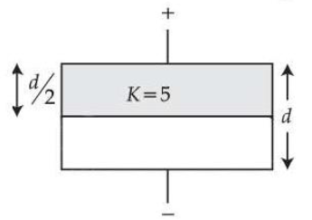
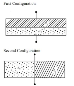
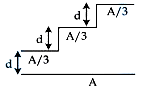
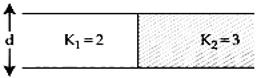
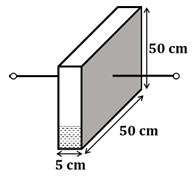
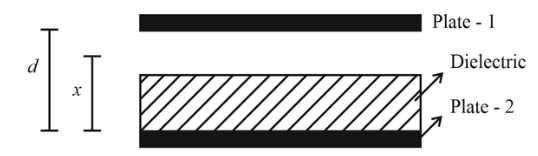
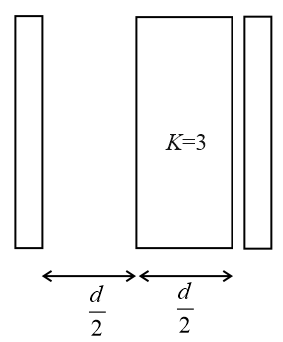
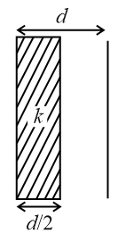
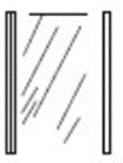
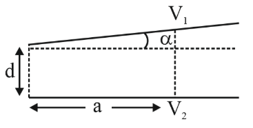
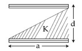
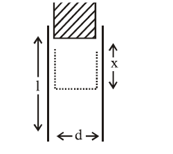
We have two large square plates of side $$a$$ separated by a small distance $$d$$, with $$d \ll a$$ so that edge effects can be ignored and the electric field between the plates is practically uniform in the vertical direction. The space between the plates is partly air and partly filled with a dielectric of constant $$K$$. The interface between the dielectric and the air is a straight line joining the bottom left corner of the plates to the top right corner, so that at the left edge there is no dielectric while at the right edge the entire gap is filled with dielectric. In the cross-section (an $$x\!-\!y$$ plane) the dielectric therefore occupies the lower triangular region, and the air occupies the upper triangular region.
To find the total capacitance we slice the plates into thin vertical strips, each of width $$dx$$, parallel to the interface. Every strip behaves as an independent capacitor because all strips have the same potential difference $$V$$ across the plates. Hence the capacitances of the strips are in parallel and will add algebraically.
For a strip situated at a horizontal coordinate $$x$$ (measured from the left edge, $$0 \le x \le a$$), the diagonal interface meets the strip at a height that is proportional to $$x$$. Since the interface goes from the bottom left corner $$(x=0,y=0)$$ to the top right corner $$(x=a,y=d)$$, the thickness of the dielectric layer inside this strip is
$$t_2=\frac{x}{a}\,d,$$
and the remaining thickness is air, namely
$$t_1=d-t_2=d-\frac{x}{a}d=d\Bigl(1-\frac{x}{a}\Bigr).$$
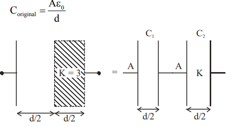
Thus, along the field direction, the air layer and the dielectric layer are connected in series. For a series combination of two capacitors of plate area $$A$$ and thicknesses $$t_1$$ and $$t_2$$ with dielectric constants $$\varepsilon_1$$ and $$\varepsilon_2$$, the formula is first stated:
$$\frac{1}{C_{\text{series}}}=\frac{t_1}{\varepsilon_1 A}+\frac{t_2}{\varepsilon_2 A}.$$
Here $$\varepsilon_1=\varepsilon_0$$ (air), $$\varepsilon_2=K\varepsilon_0$$ (dielectric), and the area of the strip is
$$A= (\text{depth})\times (\text{width}) = a\;dx.$$
Substituting these into the formula we get
$$\frac{1}{dC(x)}=\frac{t_1}{\varepsilon_0 A}+\frac{t_2}{K\varepsilon_0 A}
=\frac{d\bigl(1-\dfrac{x}{a}\bigr)}{\varepsilon_0 a\,dx}
+\frac{d\dfrac{x}{a}}{K\varepsilon_0 a\,dx}.$$
Combining the two fractions in the numerator:
$$\frac{1}{dC(x)}=\frac{d}{\varepsilon_0 a\,dx}
\Bigl[\,1-\frac{x}{a}+\frac{x}{aK}\Bigr]
=\frac{d}{\varepsilon_0 a\,dx}
\Bigl[1-\frac{x}{a}\Bigl(1-\frac{1}{K}\Bigr)\Bigr].$$
Hence the capacitance of the strip is
$$dC(x)=\frac{\varepsilon_0 a\,dx}
{d\Bigl[1-\dfrac{x}{a}\Bigl(1-\dfrac{1}{K}\Bigr)\Bigr]}.$$
For convenience define
$$\alpha=1-\frac{1}{K},$$
so that
$$dC(x)=\frac{\varepsilon_0 a\,dx}{d\bigl[1-\dfrac{\alpha x}{a}\bigr]}.$$
All these strip capacitances are in parallel, so the total capacitance is obtained by integrating $$dC(x)$$ from $$x=0$$ to $$x=a$$:
$$C=\int_{0}^{a} dC(x)=\frac{\varepsilon_0 a}{d}\int_{0}^{a}
\frac{dx}{1-\dfrac{\alpha x}{a}}.$$
We now carry out the integral. First rewrite the denominator:
$$1-\frac{\alpha x}{a}=1-\alpha\left(\frac{x}{a}\right).$$
Let us substitute
$$u=1-\alpha\left(\frac{x}{a}\right)\quad\Longrightarrow\quad
du=-\frac{\alpha}{a}\,dx\quad\Longrightarrow\quad
dx=-\frac{a}{\alpha}\,du.$$
When $$x=0$$, $$u=1$$; when $$x=a$$, $$u=1-\alpha.$$ Therefore
$$
\begin{aligned}
C & =\frac{\varepsilon_0 a}{d}\int_{x=0}^{x=a}
\frac{dx}{1-\dfrac{\alpha x}{a}}
=\frac{\varepsilon_0 a}{d}\int_{u=1}^{u=1-\alpha}
\frac{-\dfrac{a}{\alpha}\,du}{u} \\
& =\frac{\varepsilon_0 a}{d}\cdot\frac{a}{\alpha}
\int_{u=1-\alpha}^{u=1}\frac{du}{u} \\
& =\frac{\varepsilon_0 a^2}{d\alpha}
\bigl[\ln u\bigr]_{u=1-\alpha}^{u=1}.
\end{aligned}
$$
Evaluating the limits:
$$
\begin{aligned}
\bigl[\ln u\bigr]_{1-\alpha}^{1}
&=\ln(1)-\ln(1-\alpha)\\
&=0-\ln(1-\alpha)\\
&=-\ln(1-\alpha).
\end{aligned}
$$
So
$$C=\frac{\varepsilon_0 a^2}{d\alpha}\,\bigl[-\ln(1-\alpha)\bigr]
=\frac{\varepsilon_0 a^2}{d\alpha}\,\ln\!\Bigl(\frac{1}{1-\alpha}\Bigr).$$
Recall that $$\alpha=1-\dfrac{1}{K} \; \Rightarrow \; 1-\alpha=\dfrac{1}{K}.$$ Substituting this back in gives
$$
C=\frac{\varepsilon_0 a^2}{d\alpha}\,\ln(K)
=\frac{\varepsilon_0 a^2}{d}\;
\frac{1}{1-\dfrac{1}{K}}\,\ln K.
$$
Simplifying the fraction:
$$
\frac{1}{1-\dfrac{1}{K}}
=\frac{1}{\dfrac{K-1}{K}}
=\frac{K}{K-1}.
$$
Therefore
$$
C=\frac{\varepsilon_0 a^2}{d}\,
\frac{K}{K-1}\,\ln K
=\frac{K\varepsilon_0 a^2}{d\,(K-1)}\,\ln K.
$$
This matches Option 2 in the given list.
Hence, the correct answer is Option 2.
A parallel plate capacitor is of area 6 cm$$^2$$ and a separation 3 mm. The gap is filled with three dielectric materials of equal thickness (see figure) with dielectric constant $$K_1 = 10$$, $$K_2 = 12$$ and $$K_3 = 14$$. The dielectric constant of a material which when fully inserted in above capacitor, gives same capacitance would be:
A parallel plate capacitor with square plates is filled with four dielectrics of dielectric constants $$K_1$$, $$K_2$$, $$K_3$$, $$K_4$$ arranged as shown in the figure. The effective dielectric constant $$K$$ will be:
A system of three charges are placed as shown in the figure:
If $$D >> d$$, the potential energy of the system is best given by:
In the figure shown below, the charge on the left plate of the $$10\mu F$$ capacitor is $$-30\mu C$$. The charge on the right plate of the $$6\mu F$$ capacitor is:
Seven capacitors, each of capacitance $$2\mu F$$, are to be connected in a configuration to obtain an effective capacitance of $$\left(\frac{6}{13}\right)\mu F$$. Which of the combinations, shown in figures below, will achieve the desired value?
The electric field in a region is given by $$\vec{E} = (Ax + B)\hat{i}$$, where E is in NC$$^{-1}$$ and $$x$$ is in metres. The values of constants are A = 20 SI unit and B = 10 SI unit. If the potential at $$x = 1$$ is $$V_1$$ and that at $$x = -5$$ is $$V_2$$, then $$V_1 - V_2$$ is:
We have the electric field in the region given as $$\vec E = (Ax + B)\,\hat i$$, where the constants are $$A = 20\text{ (SI units)}$$ and $$B = 10\text{ (SI units)}$$.
For one-dimensional situations, the relation between electric field and electric potential is stated first:
$$E_x = -\frac{dV}{dx}.$$
This can be rewritten as
$$dV = -E_x\,dx.$$
The potential difference between two points $$x = x_1$$ and $$x = x_2$$ is therefore obtained by integrating:
$$V(x_2) - V(x_1) = -\int_{x_1}^{x_2} E_x \, dx.$$
In our problem the two positions are $$x_1 = -5\text{ m}$$ and $$x_2 = 1\text{ m}$$, with corresponding potentials $$V_2$$ and $$V_1$$. Substituting these limits,
$$V_1 - V_2 = -\int_{-5}^{1} (Ax + B)\,dx.$$
Now we substitute the numerical values of $$A$$ and $$B$$:
$$V_1 - V_2 = -\int_{-5}^{1} \bigl(20x + 10\bigr)\,dx.$$
We carry out the algebraic integration term by term. The integral of $$20x$$ is $$20 \cdot \dfrac{x^2}{2} = 10x^2$$, and the integral of $$10$$ is $$10x$$. So,
$$\int (20x + 10)\,dx \;=\; 10x^2 + 10x.$$
Placing the limits gives
$$V_1 - V_2 = -\Bigl[\,10x^2 + 10x\,\Bigr]_{x=-5}^{x=1}.$$
First we evaluate the bracket at the upper limit $$x = 1$$:
$$10(1)^2 + 10(1) = 10 + 10 = 20.$$
Next we evaluate at the lower limit $$x = -5$$:
$$10(-5)^2 + 10(-5) = 10(25) - 50 = 250 - 50 = 200.$$
Now we find the difference of the two bracketed values:
$$\Bigl(10x^2 + 10x\Bigr)_{1} - \Bigl(10x^2 + 10x\Bigr)_{-5} = 20 - 200 = -180.$$
Finally, we remember the overall minus sign outside the bracket:
$$V_1 - V_2 = -(-180) = 180\ \text{V}.$$
Hence, the correct answer is Option C.
The parallel combination of two air filled parallel plate capacitors of capacitance C and nC is connected to a battery of voltage, V. When the capacitors are fully charged, the battery is removed and after that a dielectric material of dielectric constant K is placed between the two plates of the first capacitor. The new potential difference of the combined system is:
First we note the basic relation for any capacitor, namely the charge-voltage relation $$Q = C\,V$$ where $$C$$ is the capacitance, $$V$$ the potential difference across its plates and $$Q$$ the magnitude of charge stored on either plate.
The two given capacitors are air-filled parallel-plate capacitors having capacitances
$$C_1 = C \qquad\text{and}\qquad C_2 = nC.$$
Because they are connected in parallel to the same battery, the potential difference across each capacitor is initially the battery voltage $$V$$. Using $$Q = C\,V$$ we obtain their individual charges just after connection to the battery:
$$Q_1^{\text{(initial)}} = C_1 V = C\,V,$$
$$Q_2^{\text{(initial)}} = C_2 V = nC\,V.$$
The total charge residing on the combination is therefore
$$Q_{\text{total}}^{\text{(initial)}} \;=\; Q_1^{\text{(initial)}} + Q_2^{\text{(initial)}} \;=\; C\,V + nC\,V \;=\; (n + 1)\,C\,V.$$
Now the battery is carefully removed. When the external circuit is opened in this way, no further charge can flow into or out of the parallel combination, so the total charge remains fixed at the value just calculated:
$$Q_{\text{total}} = (n + 1)\,C\,V \quad\text{(conserved)}.$$
After the battery has been detached, a dielectric slab of dielectric constant $$K$$ is inserted fully between the plates of the first capacitor only. Inserting a dielectric multiplies the capacitance by $$K$$, so the new capacitances are
$$C_1' = K\,C \qquad\text{and}\qquad C_2' = nC \;(\text{unchanged}).$$
Because the connecting wires joining the two capacitors are still intact, the two capacitors remain in parallel and must therefore share a common new potential difference. Let us denote this unknown final potential difference by $$V'$$.
Using $$Q = C\,V$$ once more, the individual charges after insertion of the dielectric become
$$Q_1' = C_1' V' = K\,C\,V',$$
$$Q_2' = C_2' V' = nC\,V'.$$
The total charge after the insertion is thus
$$Q_{\text{total}}^{\text{(final)}} = Q_1' + Q_2' = K\,C\,V' + nC\,V' = (K + n)\,C\,V'.$$
But charge is conserved, so this final total charge must equal the initial total charge:
$$(K + n)\,C\,V' = (n + 1)\,C\,V.$$
We divide both sides by $$C$$ to eliminate the common factor and then solve for $$V'$$:
$$(K + n)\,V' = (n + 1)\,V,$$
$$V' = \frac{(n + 1)\,V}{K + n}.$$
This is the new potential difference across each capacitor in the parallel combination after the dielectric has been introduced.
Hence, the correct answer is Option A.
Two identical parallel plate capacitors, of capacitance C each, have plates of area A, separated by a distance d. The space between the plates of the two capacitors, is filled with three dielectrics, of equal thickness and dielectric constants K$$_1$$, K$$_2$$ and K$$_3$$. The first capacitor is filled as shown in figure I, and the second one is filled as shown in figure II.
If these two modified capacitors are charged by the same potential V, the ratio of the energy stored in the two, would be (E$$_1$$ refers to capacitor I and E$$_2$$ to capacitor II):
Voltage rating of a parallel plate capacitor is 500 V. Its dielectric can withstand a maximum electric field of $$10^{6}$$ V/m. The plate area is $$10^{-4}$$ m$$^{2}$$. What is the dielectric constant if the capacitance is 15 pF? (given $$\varepsilon_0 = 8.86 \times 10^{-12}$$ C$$^{2}$$/Nm$$^{2}$$)
We are dealing with a parallel-plate capacitor completely filled with a dielectric. For such a capacitor the capacitance is given by the well-known formula
$$C \;=\; \kappa \,\varepsilon_0 \,\dfrac{A}{d},$$
where $$C$$ is the capacitance, $$\kappa$$ is the dielectric constant (relative permittivity) we have to find, $$\varepsilon_0$$ is the permittivity of free space, $$A$$ is the plate area and $$d$$ is the separation between the plates.
The separation $$d$$ is not given directly, but we do know the largest voltage the capacitor can sustain (its voltage rating) and the largest electric field the dielectric can withstand. The electric field in a parallel-plate capacitor is related to the voltage by the basic relation
$$E \;=\; \dfrac{V}{d}.$$
Re-arranging this relation to express $$d$$ in terms of the voltage $$V$$ and the maximum permissible field $$E_{\text{max}}$$, we get
$$d \;=\; \dfrac{V_{\text{max}}}{E_{\text{max}}}.$$
Now we substitute the given numerical values. The maximum voltage is $$V_{\text{max}} = 500 \text{ V}$$ and the maximum field is $$E_{\text{max}} = 10^{6} \text{ V m}^{-1}$$. Hence
$$d \;=\; \dfrac{500}{10^{6}} \text{ m} \;=\; 5 \times 10^{-4} \text{ m}.$$
Next, we substitute this $$d$$ into the capacitance formula to solve for the dielectric constant $$\kappa$$. First rewrite the capacitance formula explicitly for $$\kappa$$:
$$\kappa \;=\; \dfrac{C\,d}{\varepsilon_0\,A}.$$
All quantities in this expression are now known:
Capacitance: $$C = 15 \text{ pF} = 15 \times 10^{-12} \text{ F}$$.
Plate separation: $$d = 5 \times 10^{-4} \text{ m}$$ (found above).
Permittivity of free space: $$\varepsilon_0 = 8.86 \times 10^{-12} \text{ C}^2\text{ N}^{-1}\text{ m}^{-2}$$.
Plate area: $$A = 10^{-4} \text{ m}^2$$.
Substituting each value carefully we obtain
$$\kappa \;=\; \dfrac{(15 \times 10^{-12})\,(5 \times 10^{-4})}{(8.86 \times 10^{-12})\,(10^{-4})}.$$
First, multiply the numbers in the numerator:
$$15 \times 5 = 75,$$
and combine the powers of ten:
$$10^{-12} \times 10^{-4} = 10^{-16}.$$
Thus the numerator becomes
$$75 \times 10^{-16} = 7.5 \times 10^{-15}.$$
For the denominator, multiply the constants:
$$8.86 \times 1 = 8.86,$$
and combine the powers of ten:
$$10^{-12} \times 10^{-4} = 10^{-16}.$$
Hence, the denominator is
$$8.86 \times 10^{-16}.$$
Now we divide numerator by denominator:
$$\kappa \;=\; \dfrac{7.5 \times 10^{-15}}{8.86 \times 10^{-16}}.$$
Because both numerator and denominator contain a factor of $$10^{-16}$$, canceling that common factor leaves a single factor of $$10^{+1}$$ (since $$10^{-15}/10^{-16} = 10^{1}$$):
$$\kappa \;=\; \dfrac{7.5}{8.86}\,\times\,10^{1}.$$
Evaluating the numerical fraction,
$$\dfrac{7.5}{8.86} \approx 0.846.$$
Multiplying by $$10^{1}$$ (that is, by 10) gives
$$\kappa \approx 0.846 \times 10 = 8.46.$$
The value rounds to $$\kappa \approx 8.5$$, matching one of the listed choices.
Hence, the correct answer is Option B.
A capacitor with capacitance 5 $$\mu$$F is charged to 5 $$\mu$$C. If the plates are pulled apart to reduce the capacitance to 2 $$\mu$$F, how much work is done?
We begin by noting that the charge on the capacitor is kept constant, because the plates are merely pulled apart without any external circuit connected. So throughout the process we have $$Q = 5\;\mu\text{C} = 5 \times 10^{-6}\;\text{C}.$$
The electrostatic energy stored in a charged capacitor in terms of its charge and capacitance is given by the formula
$$U = \frac{Q^{2}}{2C}.$$
Initially, the capacitance is $$C_i = 5\;\mu\text{F} = 5 \times 10^{-6}\;\text{F}.$$ Substituting the known values into the energy formula, we find
$$U_i \;=\; \frac{Q^{2}}{2C_i} \;=\; \frac{(5 \times 10^{-6})^{2}}{2 \times 5 \times 10^{-6}}\; \text{J}.$$
Carrying out the algebra step by step, first square the charge:
$$Q^{2} = (5 \times 10^{-6})^{2} = 25 \times 10^{-12}.$$
Now form the denominator:
$$2 \times C_i = 2 \times 5 \times 10^{-6} = 10 \times 10^{-6} = 1 \times 10^{-5}.$$
So
$$U_i = \frac{25 \times 10^{-12}}{1 \times 10^{-5}} = 25 \times 10^{-12}\times 10^{5} = 25 \times 10^{-7}\;\text{J} = 2.5 \times 10^{-6}\;\text{J}.$$
Next, the plates are separated so that the capacitance becomes $$C_f = 2\;\mu\text{F} = 2 \times 10^{-6}\;\text{F}.$$ The charge is still $$Q = 5 \times 10^{-6}\;\text{C},$$ so the final energy is
$$U_f \;=\; \frac{Q^{2}}{2C_f} \;=\; \frac{25 \times 10^{-12}}{2 \times 2 \times 10^{-6}}\; \text{J}.$$
Simplifying the denominator gives
$$2 \times 2 \times 10^{-6} = 4 \times 10^{-6},$$
and therefore
$$U_f = \frac{25 \times 10^{-12}}{4 \times 10^{-6}} = 25 \times 10^{-12} \times \frac{1}{4} \times 10^{6} = \frac{25}{4} \times 10^{-6}\;\text{J} = 6.25 \times 10^{-6}\;\text{J}.$$
The work done by the external agent in pulling the plates apart equals the increase in the electrostatic energy, because the system gains this additional energy:
$$W = U_f - U_i.$$
Substituting the computed energies, we have
$$W = 6.25 \times 10^{-6}\;\text{J} \;-\; 2.5 \times 10^{-6}\;\text{J} = 3.75 \times 10^{-6}\;\text{J}.$$
Hence, the correct answer is Option D.
A parallel plate capacitor has 1$$\mu$$F capacitance. One of its two plates is given +2$$\mu$$C charge and the other plate, +4$$\mu$$C charge. The potential difference developed across the capacitor is:
We have an isolated parallel-plate capacitor whose capacitance is given as $$C = 1\;\mu\text{F} = 1 \times 10^{-6}\,\text{F}.$$
The problem states that one conducting plate is provided with a charge of $$+2\;\mu\text{C}$$ while the other plate is provided with a charge of $$+4\;\mu\text{C}.$$ Let us denote these charges as
$$Q_1 = +2\;\mu\text{C}, \qquad Q_2 = +4\;\mu\text{C}.$$
For any capacitor, the electric field (and therefore the potential difference) is produced only by that part of the charge which is opposite and equal on the two plates. Any charge that is common to both plates does not contribute to the field between them because its electric effects cancel out internally.
Mathematically we decompose the charges on the plates into two parts:
1. A common charge that is present, with the same sign and magnitude, on both plates.
2. An opposite charge that is equal in magnitude and opposite in sign on the two plates; this part alone decides the potential difference.
The common charge is obtained by averaging the two given charges:
$$Q_{\text{common}} = \frac{Q_1 + Q_2}{2} = \frac{(+2\;\mu\text{C}) + (+4\;\mu\text{C})}{2} = \frac{6\;\mu\text{C}}{2} = 3\;\mu\text{C}.$$
Subtracting this common charge from each plate’s total charge leaves us with the opposite (effective) charge:
For plate 1: $$Q_{1,\text{eff}} = Q_1 - Q_{\text{common}} = 2\;\mu\text{C} - 3\;\mu\text{C} = -1\;\mu\text{C}.$$
For plate 2: $$Q_{2,\text{eff}} = Q_2 - Q_{\text{common}} = 4\;\mu\text{C} - 3\;\mu\text{C} = +1\;\mu\text{C}.$$
Clearly, the two effective charges are equal in magnitude (1 μC) and opposite in sign, which is exactly the situation for an ordinarily charged capacitor.
Hence the magnitude of the charge that actually participates in producing the potential difference is
$$Q_{\text{eff}} = 1\;\mu\text{C} = 1 \times 10^{-6}\,\text{C}.$$
Now we use the fundamental capacitor formula relating charge, capacitance and potential difference:
$$V = \frac{Q_{\text{eff}}}{C}.$$
Substituting the known values,
$$V = \frac{1 \times 10^{-6}\,\text{C}}{1 \times 10^{-6}\,\text{F}} = 1\;\text{V}.$$
Therefore, the potential difference developed across the capacitor is $$1\;\text{volt}.$$ Hence, the correct answer is Option A.
Four equal point charges $$Q$$ each are placed in the $$xy$$ plane at $$(0, 2)$$, $$(4, 2)$$, $$(4, -2)$$ and $$(0, -2)$$. The work required to put a fifth charge $$Q$$ at the origin of the coordinate system will be:
We have four identical point charges of magnitude $$Q$$ lying in the $$xy$$-plane at the Cartesian coordinates $$(0,\,2)\,,\;(4,\,2)\,,\;(4,\,-2)\;$$and$$(0,\,-2)$$. We wish to calculate the external work that must be done to slowly bring a fifth charge, also of magnitude $$Q$$, from infinity to the origin $$(0,\,0)$$.
The work required equals the increase in the electrostatic potential energy of the system, and that is given by the product of the fifth charge and the electric potential already present at the origin because of the four fixed charges. Symbolically,
$$W = q\,V_{\text{origin}},$$
where here $$q = Q$$ (the charge we are bringing in) and $$V_{\text{origin}}$$ is the net electric potential at the origin due to the other four charges.
The electric potential due to a single point charge is, by definition,
$$V = \dfrac{1}{4\pi\varepsilon_0}\,\dfrac{q}{r},$$
where $$r$$ is the straight-line distance from the charge to the point where the potential is being evaluated. The superposition principle tells us that potentials simply add algebraically. Therefore we first find the distance of each of the four charges from the origin, then add the individual contributions.
For the charge at $$(0,\,2)$$ we note that it lies on the $$y$$-axis 2 units above the origin, so
$$r_1 = \sqrt{0^2 + 2^2} = 2.$$
The charge at $$(0,\,-2)$$ is 2 units below the origin, giving
$$r_2 = \sqrt{0^2 + (-2)^2} = 2.$$
The charge at $$(4,\,2)$$ has coordinates that produce
$$r_3 = \sqrt{4^2 + 2^2} = \sqrt{16 + 4} = \sqrt{20} = 2\sqrt{5}.$$
Finally, for the charge at $$(4,\,-2)$$ we obtain the identical distance
$$r_4 = 2\sqrt{5}.$$
Now we compute each potential contribution. Using $$k = \dfrac{1}{4\pi\varepsilon_0}$$ for brevity, we write
$$V_1 = k\,\dfrac{Q}{r_1} = k\,\dfrac{Q}{2},$$
$$V_2 = k\,\dfrac{Q}{r_2} = k\,\dfrac{Q}{2},$$
$$V_3 = k\,\dfrac{Q}{r_3} = k\,\dfrac{Q}{2\sqrt{5}},$$
$$V_4 = k\,\dfrac{Q}{r_4} = k\,\dfrac{Q}{2\sqrt{5}}.$$
Adding them, the total potential at the origin becomes
$$\begin{aligned} V_{\text{origin}} & = V_1 + V_2 + V_3 + V_4 \\[4pt] & = kQ\!\left(\dfrac{1}{2} + \dfrac{1}{2} + \dfrac{1}{2\sqrt{5}} + \dfrac{1}{2\sqrt{5}}\right) \\[6pt] & = kQ\!\left(1 + \dfrac{1}{\sqrt{5}}\right). \end{aligned}$$
We now substitute this potential into the work formula:
$$W = Q \, V_{\text{origin}} = Q \, \left[kQ\left(1 + \dfrac{1}{\sqrt{5}}\right)\right] = kQ^2\left(1 + \dfrac{1}{\sqrt{5}}\right).$$
Replacing $$k$$ by its explicit form $$\dfrac{1}{4\pi\varepsilon_0}$$, we obtain
$$W = \dfrac{Q^2}{4\pi\varepsilon_0}\left(1 + \dfrac{1}{\sqrt{5}}\right).$$
This matches Option C.
Hence, the correct answer is Option C.
In the given circuit, the charge on 4 μF capacitor will be:
A parallel plate capacitor having capacitance 12 pF is charged by a battery to a potential difference of 10 V between its plates. The charging battery is now disconnected and a porcelain slab of dielectric constant 6.5 is slipped between the plates. The work done by the capacitor on the slab is:
We begin by recalling the energy-charge-capacitance relation for a capacitor whose charge remains constant. The electrostatic energy stored is given by the formula
$$U=\frac{Q^{2}}{2C},$$
where $$Q$$ is the charge on the plates and $$C$$ is the capacitance. Because the battery is disconnected before the dielectric slab is introduced, the charge $$Q$$ already on the plates cannot change.
At the very start, the given parallel-plate capacitor has a capacitance
$$C_{0}=12\;\text{pF}=12\times10^{-12}\,\text{F}$$
and is charged to a potential difference
$$V_{0}=10\;\text{V}.$$
Using the definition $$Q=CV,$$ the initial charge stored on the plates is
$$Q=C_{0}V_{0}=12\times10^{-12}\,\text{F}\times10\;\text{V}=120\times10^{-12}\;\text{C}=120\;\text{pC}.$$
Squaring this charge for later use gives
$$Q^{2}=(120\;\text{pC})^{2}=120^{2}\times10^{-24}\;\text{C}^{2}=14400\times10^{-24}\;\text{C}^{2}=1.44\times10^{-20}\;\text{C}^{2}.$$
Now we compute the initial energy stored in the capacitor:
$$U_{1}=\frac{Q^{2}}{2C_{0}}=\frac{1.44\times10^{-20}\;\text{C}^{2}}{2\times12\times10^{-12}\,\text{F}}=\frac{1.44\times10^{-20}}{24\times10^{-12}}\;\text{J}.$$
Carrying out the division,
$$\frac{1.44}{24}=0.06,\qquad 10^{-20+12}=10^{-8},$$
so
$$U_{1}=0.06\times10^{-8}\;\text{J}=6.0\times10^{-10}\;\text{J}.$$
Because $$1\;\text{pJ}=10^{-12}\;\text{J},$$ this is
$$U_{1}=600\;\text{pJ}.$$
Next, a porcelain slab with dielectric constant $$k=6.5$$ is inserted. For a completely filled capacitor the capacitance multiplies by the dielectric constant, giving
$$C_{2}=kC_{0}=6.5\times12\;\text{pF}=78\;\text{pF}=78\times10^{-12}\,\text{F}.$$
The charge is still $$Q=120\;\text{pC},$$ so the new energy becomes
$$U_{2}=\frac{Q^{2}}{2C_{2}}=\frac{1.44\times10^{-20}}{2\times78\times10^{-12}}\;\text{J}=\frac{1.44\times10^{-20}}{156\times10^{-12}}\;\text{J}.$$
Simplifying the numerical factor,
$$\frac{1.44}{156}=0.00923077,\qquad 10^{-20+12}=10^{-8},$$
hence
$$U_{2}=0.00923077\times10^{-8}\;\text{J}=9.23\times10^{-11}\;\text{J}.$$
Converting to picojoules,
$$U_{2}=92.3\;\text{pJ}.$$
The capacitor’s energy has decreased, and by conservation of energy that decrease appears as work done by the capacitor on the dielectric slab. Therefore the work done is
$$W=U_{1}-U_{2}=600\;\text{pJ}-92.3\;\text{pJ}=507.7\;\text{pJ}\approx508\;\text{pJ}.$$
Hence, the correct answer is Option C.
In free space, a particle A of charge 1 μC is held fixed at point P. Another particle B of the same charge and mass 4 μg is kept at a distance of 1 mm from P. If B is released, then its velocity at a distance of 9 mm from P is:
[Take $$\frac{1}{4\pi\varepsilon_0} = 9 \times 10^9$$ N m$$^2$$ C$$^{-2}$$]
We have two identical point charges, each of magnitude $$q = 1\;\mu{\rm C} = 1 \times 10^{-6}\;{\rm C}$$. Charge A is fixed at point P, while charge B (mass $$m$$) is released from rest. Because the charges are like-signed, the electrostatic force is repulsive, so B moves away from A. The mechanical energy of the system is conserved because no non-conservative forces act in free space.
First we translate all given quantities into SI units:
$$q = 1 \times 10^{-6}\;{\rm C}$$
$$m = 4\;\mu{\rm g} = 4 \times 10^{-6}\;{\rm kg}$$ (since $$1\;\mu{\rm g} = 10^{-6}\;{\rm kg}$$)
Initial separation $$r_i = 1\;{\rm mm} = 1 \times 10^{-3}\;{\rm m}$$
Final separation $$r_f = 9\;{\rm mm} = 9 \times 10^{-3}\;{\rm m}$$
The Coulomb constant is provided as $$k = \dfrac{1}{4\pi\varepsilon_0} = 9 \times 10^{9}\;{\rm N\,m^2\,C^{-2}}.$$
The electrostatic potential energy of two point charges is given by the formula
$$U = k\,\frac{q_1 q_2}{r}.$$
Here $$q_1 = q_2 = q$$, so
$$U = k\,\frac{q^2}{r}.$$
We calculate the initial potential energy at separation $$r_i$$:
$$U_i = k\,\frac{q^2}{r_i} = \left(9 \times 10^{9}\right) \frac{\left(1 \times 10^{-6}\right)^2}{1 \times 10^{-3}} = 9 \times 10^{-3}\times\frac{1}{1 \times 10^{-3}} = 9\;{\rm J}.$$
Next, the potential energy when the separation becomes $$r_f$$ is
$$U_f = k\,\frac{q^2}{r_f} = \left(9 \times 10^{9}\right) \frac{\left(1 \times 10^{-6}\right)^2}{9 \times 10^{-3}} = 9 \times 10^{-3}\times\frac{1}{9 \times 10^{-3}} = 1\;{\rm J}.$$
The change in potential energy is therefore
$$\Delta U = U_i - U_f = 9\;{\rm J} - 1\;{\rm J} = 8\;{\rm J}.$$
Since particle B starts from rest, its initial kinetic energy is zero. By conservation of mechanical energy, the decrease in potential energy equals the increase in kinetic energy of B:
$$\frac{1}{2} m v^2 = \Delta U.$$
Substituting $$m = 4 \times 10^{-6}\;{\rm kg}$$ and $$\Delta U = 8\;{\rm J}$$ gives
$$\frac{1}{2}\,(4 \times 10^{-6})\,v^2 = 8,$$ $$\Rightarrow\; (2 \times 10^{-6})\,v^2 = 8,$$ $$\Rightarrow\; v^2 = \frac{8}{2 \times 10^{-6}} = 4 \times 10^{6},$$ $$\Rightarrow\; v = \sqrt{4 \times 10^{6}} = 2 \times 10^{3}\;{\rm m\,s^{-1}}.$$
Thus the speed of particle B when it is 9 mm away from P is $$2.0 \times 10^{3}\;{\rm m\,s^{-1}}.$$
Hence, the correct answer is Option 3.
The equivalent capacitance between A and B in the circuit given below is:
A parallel plate capacitor of capacitance 90 pF is connected to a battery of EMF 20 V. If a dielectric material of dielectric constant $$K = \frac{5}{3}$$ is inserted between the plates, the magnitude of the induced charge will be:
We have a parallel-plate capacitor whose initial capacitance is
$$C_0 = 90 \,\text{pF} = 90 \times 10^{-12}\,\text{F}.$$
The plates are connected to a battery that keeps a constant potential difference
$$V = 20\,\text{V}.$$
The free charge already present on the plates before any dielectric is introduced is obtained from the basic definition of capacitance
$$C = \dfrac{Q}{V}\; \Longrightarrow\; Q_0 = C_0 V.$$
Substituting the given numbers,
$$Q_0 = (90 \times 10^{-12}\,\text{F})(20\,\text{V}) = 1800 \times 10^{-12}\,\text{C} = 1.8 \times 10^{-9}\,\text{C} = 1.8\,\text{nC}.$$
Now a slab of dielectric having dielectric constant $$K=\dfrac{5}{3}$$ completely fills the space between the plates. As long as the battery remains connected, the voltage stays fixed at $$20\ \text{V}$$, but the capacitance becomes
$$C = K C_0 = \dfrac{5}{3}\,(90 \times 10^{-12}\,\text{F}) = 150 \times 10^{-12}\,\text{F} = 150\,\text{pF}.$$
With this new capacitance, the free charge residing on the metal plates is
$$Q_{\text{free}} = C V = (150 \times 10^{-12}\,\text{F})(20\,\text{V}) = 3000 \times 10^{-12}\,\text{C} = 3.0 \times 10^{-9}\,\text{C} = 3.0\,\text{nC}.$$
The appearance of the dielectric polarises it, creating bound (induced) charges on its two faces. In a uniformly filled capacitor the magnitude of the induced charge is related to the free charge by the well-known relation
$$Q_{\text{ind}} = Q_{\text{free}}\!\left(1 - \dfrac{1}{K}\right).$$
This comes from the vector equation $$\mathbf D = \varepsilon_0\mathbf E + \mathbf P$$ and the fact that the normal component of $$\mathbf D$$ ends on the free charge while the polarisation $$\mathbf P$$ gives the bound charge.
Substituting $$K = \dfrac{5}{3}$$ and $$Q_{\text{free}} = 3.0\,\text{nC}$$, we get
$$Q_{\text{ind}} = 3.0\,\text{nC}\!\left(1 - \dfrac{1}{\,5/3\,}\right) = 3.0\,\text{nC}\!\left(1 - \dfrac{3}{5}\right) = 3.0\,\text{nC}\!\left(\dfrac{2}{5}\right) = 1.2\,\text{nC}.$$
Thus the magnitude of the induced (bound) charge on either face of the dielectric sheet is $$1.2\,\text{nC}$$.
Hence, the correct answer is Option B.
In the following circuit the switch S is closed at t = 0. The charge on the capacitor C$$_1$$ as a function of time will be given by $$\left(C_{eq} = \frac{C_1 C_2}{C_1 + C_2}\right)$$:
A parallel plate capacitor with area 200 cm$$^2$$ and separation between the plates 1.5 cm, is connected across a battery of emf V. If the force of attraction between the plates is $$25 \times 10^{-6}$$ N, the value of V is approximately: $$\left(\varepsilon_0 = 8.85 \times 10^{-12} \frac{C^2}{N \cdot m^2}\right)$$
First, let us convert every given quantity to SI units, because all standard electrostatic formulas are written in metres, newtons, volts, etc.
The plate area is given as 200 cm$$^2$$. We know that $$1\ \text{cm} = 10^{-2}\ \text{m}$$, so
$$200\ \text{cm}^2 = 200 \times (10^{-2}\ \text{m})^2 = 200 \times 10^{-4}\ \text{m}^2 = 2 \times 10^{-2}\ \text{m}^2.$$
The separation between the plates is 1.5 cm. Converting centimetres to metres gives
$$d = 1.5\ \text{cm} = 1.5 \times 10^{-2}\ \text{m} = 0.015\ \text{m}.$$
The attractive force between the plates is given as $$25 \times 10^{-6}\ \text{N}$$, which we can write in scientific notation as
$$F = 2.5 \times 10^{-5}\ \text{N}.$$
Now we need a relation connecting this force to the potential difference V. For a parallel-plate capacitor:
Capacitance $$C = \dfrac{\varepsilon_0 A}{d}.$$
Energy stored $$U = \dfrac{1}{2} C V^2.$$
The force of attraction is obtained by differentiating the energy with respect to distance while keeping V constant. The well-known result is
$$F = \dfrac{1}{2}\,\varepsilon_0\,A\,\left(\dfrac{V}{d}\right)^2.$$
We need V, so we solve the above expression for V step by step. Starting with
$$F = \dfrac{1}{2}\,\varepsilon_0\,A\,\dfrac{V^2}{d^2},$$
multiply both sides by 2 to clear the fraction:
$$2F = \varepsilon_0\,A\,\dfrac{V^2}{d^2}.$$
Now isolate $$V^2$$ by multiplying both sides by $$d^2$$ and then dividing by $$\varepsilon_0 A$$:
$$V^2 = \dfrac{2F\,d^2}{\varepsilon_0 A}.$$
We substitute every value we have already converted:
$$V^2 = \dfrac{2 \times (2.5 \times 10^{-5}\ \text{N}) \times (0.015\ \text{m})^2}{(8.85 \times 10^{-12}\ \text{C}^2/\text{N·m}^2)\times(2 \times 10^{-2}\ \text{m}^2)}.$$
First calculate $$d^2$$:
$$d^2 = (0.015\ \text{m})^2 = 0.000225\ \text{m}^2 = 2.25 \times 10^{-4}\ \text{m}^2.$$
Next, compute the numerator:
$$2F\,d^2 = 2 \times (2.5 \times 10^{-5}) \times (2.25 \times 10^{-4})$$
$$= 5.0 \times 10^{-5} \times 2.25 \times 10^{-4}$$
$$= 11.25 \times 10^{-9} = 1.125 \times 10^{-8}.$$
Now compute the denominator:
$$\varepsilon_0 A = (8.85 \times 10^{-12}) \times (2 \times 10^{-2})$$
$$= 17.7 \times 10^{-14} = 1.77 \times 10^{-13}.$$
Putting these results into the expression for $$V^2$$ gives
$$V^2 = \dfrac{1.125 \times 10^{-8}}{1.77 \times 10^{-13}}.$$
Divide the significant figures and handle the powers of ten separately:
Numerical part: $$\dfrac{1.125}{1.77} \approx 0.636.$$
Powers of ten: $$10^{-8} / 10^{-13} = 10^{5}.$$
So
$$V^2 \approx 0.636 \times 10^{5} = 6.36 \times 10^{4}.$$
To find V, take the square root:
$$V = \sqrt{6.36 \times 10^{4}} = \sqrt{6.36}\,\sqrt{10^{4}}.$$
We know $$\sqrt{10^{4}} = 10^{2} = 100,$$ and $$\sqrt{6.36} \approx 2.523.$$
Therefore
$$V \approx 2.523 \times 100\ \text{V} \approx 252\ \text{V}.$$
This value is closest to 250 V among the given options.
Hence, the correct answer is Option C.
A capacitor C$$_1$$ is charged up to a voltage V = 60 V by connecting it to battery B through switch (1). Now C$$_1$$ is disconnected from battery and connected to a circuit consisting of two uncharged capacitors C$$_2$$ = 3.0$$\mu$$F and C$$_3$$ = 6.0$$\mu$$F through a switch (2) as shown in the figure. The sum of final charges on C$$_2$$ and C$$_3$$ is:
With switch (1) closed and switch (2) open, the battery charges the capacitor $$C_1$$ to the voltage $$V = 60\;\text{V}$$. The charge stored on $$C_1$$ just before the battery is removed is
$$Q_0 = C_1\,V \qquad -(1)$$
After the battery is disconnected, the system is isolated; hence the algebraic sum of charges on all conductors will remain constant.
Closing switch (2) inserts the two initially uncharged capacitors $$C_2 = 3.0\;\mu\text{F}$$ and $$C_3 = 6.0\;\mu\text{F}$$ in series between the two plates of $$C_1$$ (see figure in the question).
This series chain provides a continuous conducting path between the plates of $$C_1$$. Any residual potential difference across $$C_1$$ would drive a current through that path until the two plates of $$C_1$$ reached the same potential. Consequently, in the final steady state the potential difference across $$C_1$$ is zero and therefore
$$Q_{1,\text{final}} = 0 \qquad -(2)$$
Because the system is isolated, the charge that initially resided on $$C_1$$ must now be present on the other two capacitors. Hence, from charge conservation,
$$Q_2 + Q_3 = Q_0 \qquad -(3)$$
The figure supplied with the question shows $$C_1 = 0.60\;\mu\text{F}$$, so from $$(1)$$
$$Q_0 = 0.60\;\mu\text{F}\times 60\;\text{V} = 36\;\mu\text{C}$$
Substituting this value in $$(3)$$ gives
$$Q_2 + Q_3 = 36\;\mu\text{C}$$
Therefore, the sum of the final charges on $$C_2$$ and $$C_3$$ is $$36\;\mu\text{C}$$.
Answer (Option A): 36 $$\mu$$C
There is a uniform electrostatic field in a region. The potential at various points on a small sphere centred at $$P$$, in the region, is found to vary between the limits 589.0 V to 589.8 V. What is the potential at a point on the sphere whose radius vector makes an angle of 60° with the direction of the field?
We have a region in which the electro-static field is uniform. For any point whose position vector from the centre $$P$$ is $$\vec r$$ and which makes an angle $$\theta$$ with the field direction, the potential is given by the scalar-product form of the relation
$$V \;=\;V_P \;+\;(\vec E\!\cdot\!\vec r)\;=\;V_P \;+\;E\,r\cos\theta$$
where $$V_P$$ is the potential at the centre, $$E$$ is the magnitude of the uniform field and $$r$$ is the radius of the sphere. (We have taken the sign convention such that the point lying along the field direction has the larger potential; any other consistent convention finally leads to the same numeric answer.)
The observed extreme values on the sphere are
$$V_{\max}=589.8\;{\rm V},\qquad V_{\min}=589.0\;{\rm V}$$
These extremes correspond to $$\theta=0^\circ$$ and $$\theta=180^\circ$$ respectively, because $$\cos 0^\circ=+1$$ and $$\cos 180^\circ=-1$$. Substituting these two cases in the general expression:
For $$\theta = 0^\circ$$, $$V_{\max}=V_P+E r$$.
For $$\theta = 180^\circ$$, $$V_{\min}=V_P-E r$$.
Adding the two equations eliminates $$E r$$ and gives
$$2V_P = V_{\max}+V_{\min} \;=\;589.8 + 589.0 \;=\;1178.8,$$
so
$$V_P = \dfrac{1178.8}{2}=589.4\;{\rm V}.$$
Subtracting the two extreme-value equations eliminates $$V_P$$ and yields
$$2 E r = V_{\max}-V_{\min} \;=\;589.8 - 589.0 \;=\;0.8,$$
hence
$$E r = 0.4\;{\rm V}.$$
Now we want the potential at a point for which $$\theta = 60^\circ$$. Using $$\cos 60^\circ = \dfrac12$$ in the basic formula, we get
$$V = V_P + E r \cos 60^\circ = 589.4 + (0.4)\!\left(\dfrac12\right) = 589.4 + 0.2 = 589.6\;{\rm V}.$$
Hence, the correct answer is Option D.
A capacitance of 2 μF is required in an electrical circuit across a potential difference of 1.0 kV. A large number of 1 μF capacitors are available which can withstand a potential difference of not more than 300 V. The minimum number of capacitors required to achieve this is:
We are given many identical capacitors, each of capacitance $$C_0 = 1\;\mu\text{F}$$ and each safe only up to a potential difference of $$V_0 = 300\;\text{V}$$. We have to build an equivalent capacitance of $$C_{\text{eq}} = 2\;\mu\text{F}$$ that can safely withstand a total potential difference of $$V = 1000\;\text{V}$$. We may connect the available capacitors in any series-parallel combination.
First we make sure that the voltage rating is satisfied. Suppose we connect $$x$$ of the $$1\;\mu\text{F}$$ capacitors in series. A well-known result for identical capacitors in series is
$$C_{\text{series}} = \frac{C_0}{x},$$
and, because the capacitors are identical, the applied voltage divides equally, so each capacitor experiences
$$V_{\text{each}} = \frac{V}{x}.$$
To avoid exceeding the individual rating we must have
$$V_{\text{each}} \le V_0 \;\;\Longrightarrow\;\; \frac{V}{x} \le V_0.$$
Substituting the numbers,
$$\frac{1000}{x} \le 300.$$
Solving for $$x$$ we get
$$x \ge \frac{1000}{300} = 3.\overline{3}.$$
Because $$x$$ must be an integer, the smallest permissible value is
$$x = 4.$$
So each series string will contain $$4$$ capacitors. For this string the capacitance is
$$C_{\text{series}} = \frac{C_0}{4} = \frac{1\;\mu\text{F}}{4} = 0.25\;\mu\text{F}.$$
We now place several such identical strings in parallel to reach the required $$2\;\mu\text{F}$$. For capacitors in parallel the capacitances add directly, so for $$m$$ strings we have
$$C_{\text{eq}} = m \times C_{\text{series}}.$$
Requiring this to equal $$2\;\mu\text{F}$$ gives
$$m \times 0.25\;\mu\text{F} = 2\;\mu\text{F}$$
$$\Longrightarrow\;\; m = \frac{2}{0.25} = 8.$$
Thus we need $$8$$ parallel branches, each branch containing $$4$$ capacitors in series.
The total number $$N$$ of individual capacitors is therefore
$$N = m \times x = 8 \times 4 = 32.$$
Hence, the correct answer is Option A.
The energy stored in the electric field produced by a metal sphere is 4.5 J. If the sphere contains 4 $$\mu$$C charge, its radius will be: $$\left[\text{Take } : \frac{1}{4\pi\epsilon_0} = 9 \times 10^9 \text{ N m}^2 \text{ C}^{-2}\right]$$
We are told that the energy stored in the electric field of a charged metal sphere is $$U = 4.5\ \text{J}$$ and that the charge on the sphere is $$q = 4\ \mu\text{C}$$.
First we convert the charge into SI units. We have
$$4\ \mu\text{C} = 4 \times 10^{-6}\ \text{C}.$$
The electrostatic energy stored in an isolated conductor of capacitance $$C$$ carrying charge $$q$$ is given by the standard formula
$$U = \frac{q^2}{2\,C}.$$
For a spherical conductor of radius $$R$$, the capacitance is known to be
$$C = 4\pi\epsilon_0 R.$$
Substituting this value of $$C$$ into the energy formula, we get
$$U = \frac{q^2}{2 \times 4\pi\epsilon_0 R}.$$
Simplifying the denominator,
$$U = \frac{q^2}{8\pi\epsilon_0 R}.$$
We now solve this equation for the unknown radius $$R$$. Rearranging,
$$R = \frac{q^2}{8\pi\epsilon_0 U}.$$
The constant $$\dfrac{1}{4\pi\epsilon_0}$$ is given in the question as
$$\frac{1}{4\pi\epsilon_0} = 9 \times 10^{9}\ \text{N m}^2\text{ C}^{-2}.$$
Hence,
$$\frac{1}{8\pi\epsilon_0} \;=\; \frac{1}{2}\,\frac{1}{4\pi\epsilon_0} \;=\; \frac{1}{2}\left(9 \times 10^{9}\right) \;=\; 4.5 \times 10^{9}\ \text{N m}^2\text{ C}^{-2}.$$
Putting the numerical values into our expression for $$R$$, we have
$$R \;=\; \left(4.5 \times 10^{9}\right) \frac{q^2}{U}.$$
Substituting $$q = 4 \times 10^{-6}\ \text{C}$$ and $$U = 4.5\ \text{J},$$
$$q^2 = \left(4 \times 10^{-6}\right)^2 = 16 \times 10^{-12}\ \text{C}^2 = 1.6 \times 10^{-11}\ \text{C}^2.$$
Therefore,
$$R = \left(4.5 \times 10^{9}\right)\frac{1.6 \times 10^{-11}}{4.5}.$$
We notice that the factor of $$4.5$$ in the numerator and denominator cancels, leaving
$$R = 1.6 \times 10^{-11} \times 10^{9} = 1.6 \times 10^{-2}\ \text{m}.$$
In decimal form,
$$R = 0.016\ \text{m}.$$
Converting metres to millimetres ($$1\ \text{m} = 1000\ \text{mm}$$),
$$R = 0.016 \times 1000\ \text{mm} = 16\ \text{mm}.$$
Hence, the correct answer is Option B.
A combination of parallel plate capacitors is maintained at a certain potential difference.
When a 3 mm thick slab is introduced between all the plates, in order to maintain the same potential difference, the distance between the plates is increased by 2.4 mm. Find the dielectric constant of the slab.
Let initial plate separation be $$d$$, thickness of slab $$t$$=3 mm, and increase in separation =2.4 mm.
To keep the same potential difference, the effective separation must remain unchanged:
$$d=(d+2.4)−t+\frac{t}{K}$$
$$t-\frac{t}{K}=2.4$$
$$\frac{t}{K}=t-2.4$$
$$K=\frac{t}{t-2.4}=\frac{3}{3-2.4}=\frac{3}{0.6}=5$$
A combination of capacitors is set up as shown in the figure. The magnitude of the electric field, due to a point charge Q (having a charge equal to the sum of the charges on the 4 $$\mu$$F and 9 $$\mu$$F capacitors), at a point distant 30 m from it, would equal:
$$C_p = 3\ \mu\text{F} + 9\ \mu\text{F} = 12\ \mu\text{F}$$
The $$4\ \mu\text{F}$$ capacitor is in series with $$C_p$$ ($$12\ \mu\text{F}$$):
$$\frac{1}{C_{top}} = \frac{1}{4} + \frac{1}{12} = \frac{3+1}{12} = \frac{4}{12}$$
$$C_{top} = 3\ \mu\text{F}$$
Charge on the $$4\ \mu\text{F}$$ capacitor ($$q_1$$): $$q_1 = C_{top} \times V = 3\ \mu\text{F} \times 8\ \text{V} = 24\ \mu\text{C}$$
Charge on the $$9\ \mu\text{F}$$ capacitor ($$q_2$$):
$$V_p = V \times \frac{C_{series\_other}}{C_{series\_total}} = 8 \times \frac{4}{4 + 12} = 8 \times \frac{4}{16} = 2\ \text{V}$$
$$q_2 = C \times V_p = 9\ \mu\text{F} \times 2\ \text{V} = 18\ \mu\text{C}$$
$$Q = q_1 + q_2 = 24\ \mu\text{C} + 18\ \mu\text{C} = 42\ \mu\text{C} = 42 \times 10^{-6}\ \text{C}$$
$$E = \frac{kQ}{r^2}$$
$$E = \frac{9 \times 10^9 \times 42 \times 10^{-6}}{(30)^2}$$
$$E = 420\ \text{N/C}$$
The figure shows a network of capacitors where the number indicates capacitances in micro Farad. The value of capacitance C if the equivalent capacitance between point A and B is to be 1 $$\mu F$$ is:
Observe the section containing the $$6\ \mu F$$, $$12\ \mu F$$, and $$4\ \mu F$$ capacitors.
$$C_{s1} = \frac{6 \times 12}{6 + 12} = \frac{72}{18} = 4\ \mu F$$
$$C_{p1} = 4 + 4 = 8\ \mu F$$
This $$8\ \mu F$$ equivalent is in series with the $$1\ \mu F$$ capacitor at the top.
$$C_{\text{right}} = \frac{1 \times 8}{1 + 8} = \frac{8}{9}\ \mu F$$
Now, look at the branch containing the $$8\ \mu F$$ and the two $$2\ \mu F$$ capacitors.
$$C_{p2} = 2 + 2 = 4\ \mu F$$
$$C_{\text{left}} = \frac{8 \times 4}{8 + 4} = \frac{32}{12} = \frac{8}{3}\ \mu F$$
$$C_{\text{parallel}} = C_{\text{left}} + C_{\text{right}} = \frac{8}{3} + \frac{8}{9}$$
$$C_{\text{parallel}} = \frac{24 + 8}{9} = \frac{32}{9}\ \mu F$$
$$\frac{1}{C_{AB}} = \frac{1}{C} + \frac{1}{C_{\text{parallel}}}$$
$$1 = \frac{1}{C} + \frac{9}{32}$$
$$C = \frac{32}{23}\ \mu F$$
Three capacitors each of 4 $$\mu$$F are to be connected in such a way that the effective capacitance is 6 $$\mu$$F. This can be done by connecting them
We want an equivalent capacitance of $$6\,\mu\text{F}$$ using three identical capacitors, each having $$C = 4\,\mu\text{F}$$. To decide which connection gives this value, we recall two standard results for combining capacitors:
For capacitors connected in parallel, the capacitances simply add. The formula is
$$C_{\text{parallel}} = C_1 + C_2 + C_3 + \dots$$
For capacitors connected in series, the reciprocals add. The formula is
$$\frac{1}{C_{\text{series}}} = \frac{1}{C_1} + \frac{1}{C_2} + \frac{1}{C_3} + \dots$$
We now test each option one by one.
1. All three in series. Using the series formula we have
$$\frac{1}{C_{\text{eq}}} = \frac{1}{4} + \frac{1}{4} + \frac{1}{4} = \frac{3}{4},$$
so $$C_{\text{eq}} = \frac{4}{3}\,\mu\text{F} \approx 1.33\,\mu\text{F}.$$ This is far below $$6\,\mu\text{F},$$ so this arrangement does not work.
2. All three in parallel. Using the parallel formula we get
$$C_{\text{eq}} = 4 + 4 + 4 = 12\,\mu\text{F},$$
which is double the desired value. Hence this option is also unsuitable.
3. Two in parallel and the third in series with the combination. First, put two capacitors in parallel:
$$C_{\text{parallel}} = 4 + 4 = 8\,\mu\text{F}.$$
Now place this $$8\,\mu\text{F}$$ in series with the remaining $$4\,\mu\text{F}$$ capacitor. Using the series formula,
$$\frac{1}{C_{\text{eq}}} = \frac{1}{8} + \frac{1}{4} = \frac{1}{8} + \frac{2}{8} = \frac{3}{8},$$
so $$C_{\text{eq}} = \frac{8}{3}\,\mu\text{F} \approx 2.67\,\mu\text{F}.$$ This is still not the required $$6\,\mu\text{F}.$$
4. Two in series and the third in parallel with the combination. First, connect two capacitors in series. Using the series formula,
$$\frac{1}{C_{\text{series}}} = \frac{1}{4} + \frac{1}{4} = \frac{2}{4} = \frac{1}{2},$$
which gives
$$C_{\text{series}} = 2\,\mu\text{F}.$$
Now place this $$2\,\mu\text{F}$$ result in parallel with the third $$4\,\mu\text{F}$$ capacitor. Using the parallel formula,
$$C_{\text{eq}} = 2 + 4 = 6\,\mu\text{F}.$$
This matches the required effective capacitance exactly.
Since only the arrangement with two capacitors in series and one in parallel yields $$6\,\mu\text{F},$$ that is the correct choice.
Hence, the correct answer is Option D.
A uniformly charged solid sphere of radius R has potential $$V_0$$ (measured with respect to $$\infty$$) on its surface. For this sphere the equipotential surfaces with potential $$\frac{3V_0}{2}$$, $$\frac{5V_0}{4}$$, $$\frac{3V_0}{4}$$ and $$\frac{V_0}{4}$$ have radius $$R_1$$, $$R_2$$, $$R_3$$ and $$R_4$$ respectively. Then
Note: This question had two options correct at the time of examination. Proper corrections are made in the question to avoid it.
For a uniformly charged solid sphere whose total charge is $$Q$$ and radius is $$R$$, the electro-static potential at any point is obtained from the well-known results of electrostatics. We first state these results.
• At an external point, that is for $$r \ge R$$, the sphere behaves like a point charge at its centre, so
$$V_{\text{out}}(r)=\dfrac{1}{4\pi\varepsilon_0}\dfrac{Q}{r}.$$
• At an internal point, that is for $$r \le R$$, the potential is
$$V_{\text{in}}(r)=\dfrac{1}{4\pi\varepsilon_0}\dfrac{Q}{2R^3}\left(3R^2-r^2\right).$$
On the surface $$r = R$$ these two expressions must give the same value, which is the given surface potential $$V_0$$. Putting $$r = R$$ in either formula we get
$$V_0=\dfrac{1}{4\pi\varepsilon_0}\dfrac{Q}{R}.$$
For convenience we now write every subsequent potential in terms of $$V_0$$.
1. Potential inside the sphere
Substituting $$\dfrac{Q}{4\pi\varepsilon_0} = V_0R$$ in the internal formula gives
$$V_{\text{in}}(r)=\dfrac{V_0R}{2R^3}\left(3R^2-r^2\right)=V_0\left[\dfrac{3}{2}-\dfrac{r^2}{2R^2}\right].$$
2. Potential outside the sphere
Similarly, substituting in the external formula yields
$$V_{\text{out}}(r)=V_0\dfrac{R}{r}.$$
We now locate the radii of the four equipotential surfaces mentioned in the problem.
(a) Surface with potential $$\dfrac{3V_0}{2}$$
This value of potential exceeds $$V_0$$, so the point must lie inside the sphere. We therefore equate it to the internal potential:
$$V_0\left[\dfrac{3}{2}-\dfrac{r^2}{2R^2}\right]=\dfrac{3V_0}{2}.$$
Cancelling $$V_0$$ from both sides,
$$\dfrac{3}{2}-\dfrac{r^2}{2R^2}=\dfrac{3}{2}\;\;\Longrightarrow\;\;-\dfrac{r^2}{2R^2}=0 \;\;\Longrightarrow\;\;r^2=0\;\;\Longrightarrow\;\;r=0.$$
Hence $$R_1 = 0.$$ This is only a single point—the centre of the sphere.
(b) Surface with potential $$\dfrac{5V_0}{4}$$
Again this value is larger than $$V_0$$, so we use the internal expression:
$$V_0\left[\dfrac{3}{2}-\dfrac{r^2}{2R^2}\right]=\dfrac{5V_0}{4}.$$
Dividing by $$V_0$$ and rewriting the left side with a common denominator 4,
$$\dfrac{6}{4}-\dfrac{r^2}{2R^2}=\dfrac{5}{4}.$$
Taking the difference,
$$\dfrac{6}{4}-\dfrac{5}{4}=\dfrac{r^2}{2R^2} \;\;\Longrightarrow\;\; \dfrac{1}{4}=\dfrac{r^2}{2R^2}.$$
Multiplying both sides by $$2R^2$$,
$$r^2=\dfrac{R^2}{2}\;\;\Longrightarrow\;\;r=\dfrac{R}{\sqrt{2}}.$$
Thus $$R_2=\dfrac{R}{\sqrt{2}}\;(\approx0.707\,R).$$
(c) Surface with potential $$\dfrac{3V_0}{4}$$
Now the potential is below $$V_0$$, so we are outside the sphere. Using the external formula,
$$V_0\dfrac{R}{r}=\dfrac{3V_0}{4}.$$
Eliminating $$V_0$$ gives
$$\dfrac{R}{r}=\dfrac{3}{4}\;\;\Longrightarrow\;\;r=\dfrac{4R}{3}.$$
Hence $$R_3=\dfrac{4R}{3}\;(\approx1.333\,R).$$
(d) Surface with potential $$\dfrac{V_0}{4}$$
Again we are outside, so
$$V_0\dfrac{R}{r}=\dfrac{V_0}{4}\;\;\Longrightarrow\;\;\dfrac{R}{r}=\dfrac{1}{4}\;\;\Longrightarrow\;\;r=4R.$$
Thus $$R_4=4R.$$
We have obtained
$$R_1=0,\qquad R_2=\dfrac{R}{\sqrt{2}},\qquad R_3=\dfrac{4R}{3},\qquad R_4=4R.$$
Let us now examine each option.
Option A states $$2R > R_4.$$ Substituting $$R_4=4R$$ gives $$2R > 4R,$$ which is clearly false.
Option B asserts two points: $$R_1 = 0$$ (true) and $$R_2 > (R_4 - R_3).$$ Compute $$R_4-R_3=4R-\dfrac{4R}{3}=\dfrac{12R-4R}{3}=\dfrac{8R}{3}\;( \approx 2.667\,R).$$ But $$R_2=\dfrac{R}{\sqrt{2}}\;( \approx 0.707\,R).$$ Since $$0.707\,R > 2.667\,R$$ is false, the whole option is false.
Option C says $$R_1 \neq 0$$ (false, we have $$R_1=0$$), so the option is already ruled out.
Option D combines $$R_1 = 0$$ (true) with $$R_2 < (R_4 - R_3).$$ We have $$R_2 \approx 0.707\,R$$ and $$R_4-R_3 \approx 2.667\,R$$, so indeed $$0.707\,R < 2.667\,R.$$ Both parts are satisfied, therefore Option D is correct.
Hence, the correct answer is Option D.
An electric field $$\vec{E} = \left(25\hat{i} + 30\hat{j}\right)$$ N C$$^{-1}$$ exists in a region of space. If the potential at the origin is taken to be zero then the potential at $$x = 2$$ m, $$y = 2$$ m is:
We have been given a uniform electric field $$\vec{E} = 25\hat{i} + 30\hat{j}\;{\rm N\,C^{-1}}$$. The potential at the origin $$O(0,0)$$ is specified to be zero, that is $$V_O = 0$$.
For any two points $$A$$ and $$B$$ in an electrostatic field, the potential difference is obtained from the basic relation
$$V_B - V_A = -\int_{A}^{B} \vec{E}\cdot d\vec{l}.$$
Here, point $$A$$ is the origin $$O(0,0)$$ and point $$B$$ is $$P(2\,{\rm m},\,2\,{\rm m})$$. Because the field is uniform (its components do not depend on position), we can choose any convenient path; the line integral of a constant vector reduces to the dot-product of that vector with the overall displacement. Hence,
$$V_P - V_O = -\vec{E}\cdot\vec{r},$$
where $$\vec{r}$$ is the displacement vector from $$O$$ to $$P$$.
The displacement vector is obtained component-wise:
$$\vec{r} = (2 - 0)\hat{i} + (2 - 0)\hat{j} = 2\hat{i} + 2\hat{j}\;{\rm m}.$$
Next we compute the dot product $$\vec{E}\cdot\vec{r}$$ step by step:
$$\vec{E}\cdot\vec{r} = (25\hat{i} + 30\hat{j}) \cdot (2\hat{i} + 2\hat{j})$$
$$\;\;\;= 25 \times 2 + 30 \times 2$$
$$\;\;\;= 50 + 60$$
$$\;\;\;= 110.$$
Now we insert this result into the potential difference relation:
$$V_P - V_O = -(\vec{E}\cdot\vec{r}) = -110.$$
But $$V_O = 0$$ by the condition given, so
$$V_P = -110 \;{\rm J\,C^{-1}}.$$
Hence, the correct answer is Option A.
In the figure is shown a system of four capacitors connected across a 10 V battery. The charge that will flow from switch S when it is closed is:
We first read the values written on the four capacitors in the figure. Moving clockwise from the positive terminal of the battery we have
$$C_1 = 1\;\mu{\rm F}$$, $$\; C_2 = 2\;\mu{\rm F}$$, $$\; C_3 = 2\;\mu{\rm F}$$, $$\; C_4 = 1\;\mu{\rm F}.$$
The battery maintains the upper horizontal conductor at $$+10\;{\rm V}$$ while the lower horizontal conductor is at $$0\;{\rm V}.$$ The internal junctions are
$$a\;{\rm (between}\;C_1\;{\rm and}\;C_2), \qquad b\;{\rm (between}\;C_3\;{\rm and}\;C_4).$$
At the start the switch $$S$$ between $$a$$ and $$b$$ is OPEN, so the two branches charge independently.
1. Charging of the left branch (with the switch open).
The two capacitors $$C_1$$ and $$C_2$$ are in series, so the same charge $$Q_L$$ flows through each. The equivalent capacitance of the branch is
$$C_{\,{\rm eqL}}=\frac{C_1C_2}{C_1+C_2} =\frac{(1)(2)}{1+2} =\frac{2}{3}\;\mu{\rm F}.$$
The battery is across this equivalent capacitance, hence
$$Q_L = C_{\,{\rm eqL}}\;V =\left(\frac{2}{3}\right)\times 10 = 6.667\;\mu{\rm C}.$$
Because $$Q=CV,$$ the individual voltage drops are
$$V_{C_1}=\frac{Q_L}{C_1}=\frac{6.667}{1}=6.667\;{\rm V},\qquad V_{C_2}=\frac{Q_L}{C_2}=\frac{6.667}{2}=3.333\;{\rm V}.$$
Hence the potential of junction $$a$$ (which is the lower plate of $$C_1$$ and the upper plate of $$C_2$$) is
$$V_a = 10- V_{C_1}=10-6.667 = 3.333\;{\rm V}.$$
2. Charging of the right branch (with the switch open).
Exactly the same reasoning gives for the right branch
$$C_{\,{\rm eqR}}=\frac{C_3C_4}{C_3+C_4} =\frac{(2)(1)}{2+1} =\frac{2}{3}\;\mu{\rm F},$$
so
$$Q_R=C_{\,{\rm eqR}}\;V =\left(\frac{2}{3}\right)\times10 =6.667\;\mu{\rm C}.$$
The individual drops are
$$V_{C_3}=\frac{Q_R}{C_3}=\frac{6.667}{2}=3.333\;{\rm V},\qquad V_{C_4}=\frac{Q_R}{C_4}=\frac{6.667}{1}=6.667\;{\rm V},$$
so the potential of junction $$b$$ is
$$V_b = 10- V_{C_3}=10-3.333 = 6.667\;{\rm V}.$$
Thus, before the switch is closed we have
$$V_b - V_a = 6.667 - 3.333 = 3.334\;{\rm V}\;(\approx 10/3\;{\rm V}).$$
3. Situation immediately after closing the switch.
Closing $$S$$ connects the two junctions, forcing their common potential to a single value, say $$V_f.$$
Because the conducting strip has negligible resistance, no appreciable potential difference can remain along it, so
$$V_f = V_a' = V_b'.$$
The four capacitors are now arranged as follows:
- $$C_1$$ and $$C_3$$ are each between $$+10\;{\rm V}$$ and $$V_f,$$
- $$C_2$$ and $$C_4$$ are each between $$V_f$$ and $$0\;{\rm V}.$$
Let us use charge conservation at the combined node. At that node the algebraic sum of the charges on the four plates which touch it must remain zero, because the conductor was initially neutral and it is not connected to the battery. Writing the charges on those plates after equilibrium:
$$-C_1(10-V_f) - C_3(10-V_f) + C_2V_f + C_4V_f = 0.$$
Simplifying gives
$$-(C_1+C_3)(10-V_f)+(C_2+C_4)V_f=0,$$
and therefore
$$V_f=\frac{10(C_1+C_3)}{C_1+C_2+C_3+C_4} =\frac{10(1+2)}{1+2+2+1} =\frac{30}{6}=5\;{\rm V}.$$
4. New charges on the capacitors.
Applying $$Q = CV$$ again with the new voltages we obtain
$$Q_{1}' = C_1(10-V_f)=1(10-5)=5\;\mu{\rm C},$$ $$Q_{2}' = C_2V_f =2(5)=10\;\mu{\rm C},$$ $$Q_{3}' = C_3(10-V_f)=2(10-5)=10\;\mu{\rm C},$$ $$Q_{4}' = C_4V_f =1(5)=5\;\mu{\rm C}.$$
(The primes denote charges after the switch is closed. A positive value means the plate touching the junction carries positive charge; a negative value would mean negative charge.)
5. Charge that has to pass through the switch.
Only charges situated on the plates that meet at $$a$$ and $$b$$ can flow from one junction to the other; the plates attached to the battery cannot. So we look at the change suffered by the junction plates:
At $$a$$ (the plate of $$C_2$$ and the plate of $$C_1$$):
Initial charge = $$(+6.667)\;+\;(-6.667)=0,$$
Final charge = $$(+10)\;+\;(-5)=+5\;\mu{\rm C}.$$
Thus $$a$$ has gained $$+5\;\mu{\rm C}.$$
At $$b$$ (the plate of $$C_4$$ and the plate of $$C_3$$):
Initial charge = $$(+6.667)\;+\;(-6.667)=0,$$
Final charge = $$(+5)\;+\;(-10)=-5\;\mu{\rm C}.$$
Thus $$b$$ has lost $$5\;\mu{\rm C}.$$
Because the only path joining the two points is the wire of the switch, the same $$5\;\mu{\rm C}$$ must have travelled from the higher-potential junction $$b$$ to the lower-potential junction $$a$$ to equalise them.
6. Direction.
Before closing, $$V_b > V_a,$$ so positive charge naturally flows from $$b$$ towards $$a,$$ exactly the direction stated in Option C.
Hence, the correct answer is Option C.
In the given circuit, charge $$Q_2$$ on the 2 $$\mu$$F capacitor changes as C is varied from 1 $$\mu$$F to 3 $$\mu$$F. $$Q_2$$ as a function of 'C' is given properly by: (figures are drawn schematically and are not to scale)
$$C_p = 1\ \mu\text{F} + 2\ \mu\text{F} = 3\ \mu\text{F}$$
$$C_{eq} = \frac{C \cdot C_p}{C + C_p} = \frac{3C}{C + 3}\ \mu\text{F}$$
$$Q_{total} = C_{eq} \cdot E = \frac{3CE}{C + 3}$$
$$Q_2 = \left( \frac{C_2}{C_1 + C_2} \right) Q_{total} = \left( \frac{2}{1 + 2} \right) Q_{total} = \frac{2}{3} Q_{total}$$
$$Q_2(C) = \frac{2}{3} \left( \frac{3CE}{C + 3} \right) = \frac{2CE}{C + 3}$$
$$Q_2 = 2E \left( \frac{C}{C + 3} \right) = 2E \left( 1 - \frac{3}{C + 3} \right)$$
$$\frac{dQ_2}{dC} = \frac{6E}{(C + 3)^2}$$ (always positive)
$$\frac{d^2Q_2}{dC^2} = -\frac{12E}{(C + 3)^3}$$ (always negative because capacitance is always positive)
Graph C correctly shows an increasing curve that is concave downwards.
Assume that an electric field $$\vec{E} = 30x^2\hat{i}$$ exists in space. Then the potential difference $$V_A - V_O$$, where $$V_O$$ is the potential at the origin and $$V_A$$ the potential at x = 2 m is:
We start with the fundamental electrostatic relation that connects the electric field to the electric potential:
$$\vec{E} = -\,\nabla V$$
Along the x-axis only, this gradient reduces to a simple derivative, so the x-component of the field satisfies
$$E_x = -\,\frac{dV}{dx}.$$
The problem gives the field as $$\vec{E} = 30x^2\,\hat i,$$ which means
$$E_x = 30x^2.$$
Equating the two expressions for $$E_x$$ we have
$$30x^2 = -\,\frac{dV}{dx}.$$
Now we isolate $$dV$$:
$$\frac{dV}{dx} = -30x^2 \quad\Longrightarrow\quad dV = -30x^2\,dx.$$
To obtain the potential difference between the point $$A$$ at $$x = 2\ \text{m}$$ and the origin $$O$$ at $$x = 0\ \text{m},$$ we integrate $$dV$$ from 0 to 2:
$$V_A - V_O \;=\; \int_{x=0}^{x=2} dV \;=\; \int_{0}^{2} \left(-30x^2\right)dx.$$
We compute the integral step by step:
First, integrate $$x^2$$:
$$\int x^2\,dx = \frac{x^3}{3}.$$
Now include the constant $$-30$$ and apply the limits:
$$V_A - V_O = -30 \left[ \frac{x^3}{3} \right]_{0}^{2}.$$
Simplify the coefficient:
$$-30 \times \frac{1}{3} = -10,$$
so
$$V_A - V_O = -10 \left[x^3\right]_{0}^{2}.$$
Evaluate at the upper and lower limits:
At $$x = 2,$$ $$x^3 = 2^3 = 8.$$
At $$x = 0,$$ $$x^3 = 0^3 = 0.$$
So
$$V_A - V_O = -10 \left(8 - 0\right) = -10 \times 8 = -80.$$
The SI unit of potential difference is volt, equivalent to $$\text{J C}^{-1}.$$ Thus
$$V_A - V_O = -80\ \text{J C}^{-1}.$$
The negative sign indicates that point $$A$$ is at a lower potential than the origin.
Hence, the correct answer is Option C.
A parallel plate capacitor is made of two circular plates separated by a distance of 5 mm and with a dielectric of dielectric constant 2.2 between them. When the electric field in the dielectric is $$3 \times 10^4$$ V/m, the charge density of the positive plate will be close to:
We have a parallel-plate capacitor whose space between the plates is completely filled with a dielectric material of dielectric constant $$\kappa = 2.2$$.
For such a situation the free (i.e. plate) surface charge density $$\sigma$$ is related to the electric field $$E$$ inside the dielectric through the electric displacement vector $$\vec D$$.
By definition, for an isotropic dielectric
$$\vec D \;=\; \varepsilon_0 \kappa \,\vec E$$
and the normal component of $$\vec D$$ at the surface of a conductor equals the free charge density on that surface, so
$$\sigma \;=\; D_n \;=\; \varepsilon_0 \kappa E.$$
Now we substitute the numerical values.
The permittivity of free space is
$$\varepsilon_0 = 8.854 \times 10^{-12}\;{\rm F\,m^{-1}}.$$
The given electric field is
$$E = 3 \times 10^{4}\;{\rm V\,m^{-1}}.$$
Hence
$$\sigma \;=\; \varepsilon_0 \kappa E$$
$$\;=\; (8.854 \times 10^{-12}) \times (2.2) \times (3 \times 10^{4}).$$
Carrying out the multiplication step by step, we first multiply $$\varepsilon_0$$ with $$\kappa$$:
$$8.854 \times 10^{-12} \times 2.2 \;=\; 19.4788 \times 10^{-12}$$
$$\;=\; 1.94788 \times 10^{-11}.$$
Now we multiply this by the electric field:
$$1.94788 \times 10^{-11} \times 3 \times 10^{4}$$
$$\;=\; 5.84364 \times 10^{-7} \;{\rm C\,m^{-2}}.$$
This value is practically $$5.8 \times 10^{-7}\;{\rm C\,m^{-2}}$$, which is closest to $$6 \times 10^{-7}\;{\rm C\,m^{-2}}$$ among the options provided.
Hence, the correct answer is Option A.
A parallel plate capacitor is made of two plates of length l, width w and separated by a distance d. A dielectric slab (dielectric constant K) that fits exactly between the plates is held near the edge of the plates. It is pulled into the capacitor by a force $$F = -\frac{\partial U}{\partial x}$$, where U is the energy of the capacitor when dielectric is inside the capacitor up to distance x (see the figure). If the charge on the capacitor is Q then the force on the dielectric when it is near the edge is:
Capacitance with dielectric ($$C_1$$): $$C_1 = \frac{K\epsilon_0(xw)}{d}$$
Capacitance with air ($$C_2$$): $$C_2 = \frac{\epsilon_0(l-x)w}{d}$$
Total Capacitance ($$C$$): $$C = C_1 + C_2 = \frac{\epsilon_0 w}{d} [Kx + (l-x)] = \frac{\epsilon_0 w}{d} [l + x(K-1)]$$
$$U = \frac{Q^2}{2C} = \frac{Q^2 d}{2 \epsilon_0 w [l + x(K-1)]}$$
$$F = -\frac{\partial U}{\partial x}$$
$$F = -\frac{Q^2 d}{2 \epsilon_0 w} \cdot \frac{d}{dx} [l + x(K-1)]^{-1}$$
$$F = -\frac{Q^2 d}{2 \epsilon_0 w} \cdot (-1)[l + x(K-1)]^{-2} \cdot (K-1)$$
$$F = \frac{Q^2 d (K-1)}{2 \epsilon_0 w [l + x(K-1)]^2}$$
When the slab is near the edge ($$x \approx 0$$): $$F = \frac{Q^2 d}{2 \epsilon_0 w l^2} (K-1)$$
The gap between the plates of a parallel plate capacitor of area A and distance between plates d, is filled with a dielectric whose relative permittivity varies linearly from $$\epsilon_1$$ at one plate to $$\epsilon_2$$ at the other. The capacitance of the capacitor is:
$$\epsilon(x) = \epsilon_1 + \left( \frac{\epsilon_2 - \epsilon_1}{d} \right)x$$
$$dC = \frac{\epsilon_0 \epsilon(x) A}{dx}$$
Since these slices are stacked between the plates, they are in series. For series combinations, we integrate the reciprocals ($$1/dC$$):
$$\frac{1}{C} = \int_0^d \frac{1}{dC} = \int_0^d \frac{dx}{\epsilon_0 \epsilon(x) A}$$
$$\frac{1}{C} = \frac{1}{\epsilon_0 A} \int_0^d \frac{dx}{\epsilon_1 + \left( \frac{\epsilon_2 - \epsilon_1}{d} \right)x}$$
$$\frac{1}{C} = \frac{1}{\epsilon_0 A} \cdot \left[ \frac{d}{\epsilon_2 - \epsilon_1} \ln\left( \epsilon_1 + \frac{\epsilon_2 - \epsilon_1}{d} x \right) \right]_0^d$$
$$\frac{1}{C} = \frac{d \ln(\epsilon_2 / \epsilon_1)}{\epsilon_0 A (\epsilon_2 - \epsilon_1)}$$
$$C = \frac{\epsilon_0 (\epsilon_2 - \epsilon_1) A}{d \ln(\epsilon_2 / \epsilon_1)}$$
The space between the plates of a parallel plate capacitor is filled with a 'dielectric' whose 'dielectric constant' varies with distance as per the relation: $$K(x) = K_o + \lambda x$$ ($$\lambda$$ = a constant). The capacitance C, of the capacitor, would be related to its vacuum capacitance C$$_o$$ for the relation:
The capacitance of a parallel plate capacitor with a varying dielectric constant can be found by considering the capacitor as composed of infinitesimal capacitors in series. The dielectric constant is given by $$K(x) = K_o + \lambda x$$, where $$x$$ is the distance from one plate, and the plates are separated by a distance $$d$$. The vacuum capacitance is $$C_o = \frac{\varepsilon_o A}{d}$$, where $$A$$ is the plate area and $$\varepsilon_o$$ is the permittivity of free space.
For an infinitesimal capacitor of thickness $$dx$$ at position $$x$$, the capacitance is $$dC = \frac{K(x) \varepsilon_o A}{dx}$$. Since these infinitesimal capacitors are in series, the reciprocal of the total capacitance $$C$$ is the integral of the reciprocals of the infinitesimal capacitances:
$$\frac{1}{C} = \int_0^d \frac{1}{dC} dx = \int_0^d \frac{dx}{K(x) \varepsilon_o A}$$
Substituting $$K(x) = K_o + \lambda x$$:
$$\frac{1}{C} = \int_0^d \frac{dx}{(K_o + \lambda x) \varepsilon_o A} = \frac{1}{\varepsilon_o A} \int_0^d \frac{dx}{K_o + \lambda x}$$
To solve the integral, use the substitution $$u = K_o + \lambda x$$. Then $$du = \lambda dx$$, so $$dx = \frac{du}{\lambda}$$. The limits change: when $$x = 0$$, $$u = K_o$$; when $$x = d$$, $$u = K_o + \lambda d$$. The integral becomes:
$$\int_0^d \frac{dx}{K_o + \lambda x} = \int_{K_o}^{K_o + \lambda d} \frac{1}{u} \cdot \frac{du}{\lambda} = \frac{1}{\lambda} \int_{K_o}^{K_o + \lambda d} \frac{du}{u} = \frac{1}{\lambda} \left[ \ln|u| \right]_{K_o}^{K_o + \lambda d} = \frac{1}{\lambda} \left( \ln(K_o + \lambda d) - \ln(K_o) \right) = \frac{1}{\lambda} \ln\left(\frac{K_o + \lambda d}{K_o}\right) = \frac{1}{\lambda} \ln\left(1 + \frac{\lambda d}{K_o}\right)$$
Substituting back:
$$\frac{1}{C} = \frac{1}{\varepsilon_o A} \cdot \frac{1}{\lambda} \ln\left(1 + \frac{\lambda d}{K_o}\right)$$
Recall that $$C_o = \frac{\varepsilon_o A}{d}$$, so $$\varepsilon_o A = C_o d$$. Substituting this in:
$$\frac{1}{C} = \frac{1}{C_o d} \cdot \frac{1}{\lambda} \ln\left(1 + \frac{\lambda d}{K_o}\right) = \frac{\ln\left(1 + \frac{\lambda d}{K_o}\right)}{\lambda C_o d}$$
Solving for $$C$$:
$$C = \frac{\lambda C_o d}{\ln\left(1 + \frac{\lambda d}{K_o}\right)} = \frac{\lambda d}{\ln\left(1 + \frac{\lambda d}{K_o}\right)} C_o$$
Comparing with the options, this matches Option C.
Hence, the correct answer is Option C.
Three capacitances, each of 3 $$\mu$$F, are provided. These cannot be combined to provide the resultant capacitance of:
Each capacitor has capacitance $$C = 3\,\mu\text{F}$$.
To obtain an equivalent capacitance we must connect all three capacitors, using any series-parallel arrangement. With three identical capacitors there are only four essentially different ways to combine them.
All three in series.
$$C_{\text{eq}} = \frac{C}{3} = \frac{3}{3} = 1\,\mu\text{F}$$
All three in parallel.
$$C_{\text{eq}} = 3C = 3 \times 3 = 9\,\mu\text{F}$$
Two in series, that pair in parallel with the third.
Series pair: $$C_s = \frac{C}{2} = \frac{3}{2} = 1.5\,\mu\text{F}$$
Putting this in parallel with the remaining $$3\,\mu\text{F}$$ capacitor:
$$C_{\text{eq}} = C_s + C = 1.5 + 3 = 4.5\,\mu\text{F}$$
Two in parallel, that pair in series with the third.
Parallel pair: $$C_p = 2C = 2 \times 3 = 6\,\mu\text{F}$$
Putting this in series with the remaining $$3\,\mu\text{F}$$ capacitor:
$$\frac{1}{C_{\text{eq}}} = \frac{1}{C_p} + \frac{1}{C} = \frac{1}{6} + \frac{1}{3} = \frac{1}{6} + \frac{2}{6} = \frac{3}{6}$$
so $$C_{\text{eq}} = \frac{6}{3} = 2\,\mu\text{F}$$
Thus the only equivalent capacitances obtainable with all three $$3\,\mu\text{F}$$ capacitors are
$$1\,\mu\text{F},\;2\,\mu\text{F},\;4.5\,\mu\text{F},\;9\,\mu\text{F}$$
From the given options the value that cannot be produced is
Option B: $$6\,\mu\text{F}$$.
This question has Statement-1 and Statement-2. Of the four choices given after the Statements, choose the one that best describes the two Statements.
Statement 1: No work is required to be done to move a test charge between any two points on an equipotential surface.
Statement 2: Electric lines of force at the equipotential surfaces are mutually perpendicular to each other.
Let us understand both statements step by step.
Starting with Statement 1: "No work is required to be done to move a test charge between any two points on an equipotential surface."
An equipotential surface is a surface where every point has the same electric potential. This means that for any two points A and B on such a surface, the potential difference between them is zero: $$ V_A - V_B = 0 $$ or $$ \Delta V = 0 $$.
The work done by the electric field when moving a test charge q from point A to point B is given by the formula: $$ W = -q \Delta V $$. Since $$ \Delta V = 0 $$, we have: $$ W = -q \times 0 = 0 $$.
This means the electric field does zero work. If we consider an external agent moving the charge slowly (without changing its kinetic energy), the work done by the external agent must counteract the work done by the field. Since the field does zero work, the external agent also does zero work. Therefore, Statement 1 is true.
Now, Statement 2: "Electric lines of force at the equipotential surfaces are mutually perpendicular to each other."
Electric lines of force are the same as electric field lines. We know that electric field lines are always perpendicular to equipotential surfaces. This is because if the electric field had a component tangent to the surface, it would cause a potential difference along the surface, violating the equipotential condition. However, Statement 2 claims that the field lines are mutually perpendicular to each other.
Mutually perpendicular means that the field lines intersect at right angles to one another. But at any given point on an equipotential surface, there is only one electric field direction (normal to the surface). Field lines cannot be mutually perpendicular at a point because only one line passes through each point. Moreover, when considering the entire surface, field lines are not necessarily perpendicular to each other.
For example, near a point charge, equipotential surfaces are spheres. The electric field lines are radial and diverge from the charge. They are not mutually perpendicular; instead, they are all directed radially outward or inward. In a uniform electric field, equipotential surfaces are planes, and field lines are parallel straight lines, which are not perpendicular to each other. Therefore, Statement 2 is false.
Since Statement 1 is true and Statement 2 is false, the correct choice is Option C.
Hence, the correct answer is Option C.
A charge Q is uniformly distributed over a long rod AB of length L as shown in the figure. The electric potential at the point O lying at a distance L from the end A is :
Electric potential $$dV$$ due to a small charge element $$dq$$ at a distance $$r$$ is $$dV = \frac{1}{4\pi\epsilon_0} \cdot \frac{dq}{r}$$
Consider a small element of length $$dx$$ on the rod at a distance $$x$$ from the point $$O$$. The charge on this small element is $$dq = \lambda dx = \frac{Q}{L} dx$$
The electric potential $$dV$$ at point $$O$$ due to this element is $$dV = \frac{1}{4\pi\epsilon_0} \cdot \frac{\frac{Q}{L} dx}{x}$$
To find the total potential $$V$$, we integrate from the nearest end ($$A$$) to the farthest end ($$B$$). Distance of $$A$$ from $$O = L$$ and Distance of $$B$$ from $$O = L + L = 2L$$
$$V = \int_{L}^{2L} \frac{Q}{4\pi\epsilon_0 L} \cdot \frac{dx}{x}$$
$$V = \frac{Q}{4\pi\epsilon_0 L} \ln \left( \frac{2L}{L} \right) = \frac{Q \ln 2}{4\pi\epsilon_0 L}$$
A point charge of magnitude $$+1\mu C$$ is fixed at (0, 0, 0). An isolated uncharged spherical conductor, is fixed with its center at (4, 0, 0). The potential and the induced electric field at the centre of the sphere is :
$$V_{\text{center}} = V_q + V_{\text{induced}}$$
For an uncharged spherical conductor, the net induced charge on the surface is zero. Due to the symmetry of the sphere, the potential at its center due to these induced surface charges is $$V_{\text{induced}} = \int \frac{k \cdot dq_{\text{induced}}}{R} = \frac{k}{R} \int dq_{\text{induced}} = 0$$
Thus, the potential at the center is solely due to the point charge:
$$V_{\text{center}} = \frac{kq}{r} = \frac{9 \times 10^9 \times 10^{-6}}{0.04}$$
$$V_{\text{center}} = \frac{9 \times 10^3}{4 \times 10^{-2}} = 2.25 \times 10^5\text{ V}$$
$$\vec{E}_{\text{net}} = \vec{E}_q + \vec{E}_{\text{induced}} = 0$$
$$\vec{E}_{\text{induced}} = -\vec{E}_q$$
$$E_q = \frac{kq}{r^2} = \frac{9 \times 10^9 \times 10^{-6}}{(0.04)^2}$$
$$E_q = \frac{9 \times 10^3}{16 \times 10^{-4}} = 0.5625 \times 10^7 = 5.625 \times 10^6\text{ V/m}$$
$$E_{\text{induced}} = -5.625 \times 10^6\text{ V/m}$$
A parallel plate capacitor having a separation between the plates d, plate area A and material with dielectric constant K has capacitance $$C_0$$. Now one-third of the material is replaced by another material with dielectric constant 2K, so that effectively there are two capacitors one with area $$\frac{1}{3}$$ A, dielectric constant 2K and another with area $$\frac{2}{3}$$ A and dielectric constant K. If the capacitance of this new capacitor is C then $$\frac{C}{C_0}$$ is
First, recall the formula for the capacitance of a parallel plate capacitor with a dielectric material. The capacitance is given by $$ C = \frac{K \epsilon_0 A}{d} $$, where $$ K $$ is the dielectric constant, $$ \epsilon_0 $$ is the permittivity of free space, $$ A $$ is the plate area, and $$ d $$ is the separation between the plates.
For the initial capacitor, the dielectric constant is $$ K $$, plate area is $$ A $$, and separation is $$ d $$. So, the initial capacitance $$ C_0 $$ is:
$$ C_0 = \frac{K \epsilon_0 A}{d} $$
Now, one-third of the dielectric material is replaced by another material with dielectric constant $$ 2K $$. As described, this effectively creates two capacitors in parallel: one with area $$ \frac{1}{3}A $$ and dielectric constant $$ 2K $$, and another with area $$ \frac{2}{3}A $$ and dielectric constant $$ K $$. Since they share the same plate separation $$ d $$ and are connected across the same plates, they are in parallel.
For capacitors in parallel, the total capacitance $$ C $$ is the sum of the individual capacitances. So, we need to find the capacitance of each part and add them together.
Start with the first capacitor, which has area $$ A_1 = \frac{1}{3}A $$ and dielectric constant $$ K_1 = 2K $$. Its capacitance $$ C_1 $$ is:
$$ C_1 = \frac{K_1 \epsilon_0 A_1}{d} = \frac{(2K) \epsilon_0 \left(\frac{1}{3}A\right)}{d} $$
Simplify the expression:
$$ C_1 = \frac{2K \epsilon_0 \cdot \frac{1}{3}A}{d} = \frac{2K \epsilon_0 A}{3d} $$
Notice that $$ \frac{K \epsilon_0 A}{d} $$ is exactly $$ C_0 $$, from the initial capacitance formula. So, we can write $$ C_1 $$ in terms of $$ C_0 $$:
$$ C_1 = \frac{2}{3} \times \frac{K \epsilon_0 A}{d} = \frac{2}{3} C_0 $$
Now, for the second capacitor, it has area $$ A_2 = \frac{2}{3}A $$ and dielectric constant $$ K_2 = K $$. Its capacitance $$ C_2 $$ is:
$$ C_2 = \frac{K_2 \epsilon_0 A_2}{d} = \frac{K \epsilon_0 \left(\frac{2}{3}A\right)}{d} $$
Simplify:
$$ C_2 = \frac{K \epsilon_0 \cdot \frac{2}{3}A}{d} = \frac{2K \epsilon_0 A}{3d} $$
Again, since $$ \frac{K \epsilon_0 A}{d} = C_0 $$, we have:
$$ C_2 = \frac{2}{3} \times \frac{K \epsilon_0 A}{d} = \frac{2}{3} C_0 $$
Now, the total capacitance $$ C $$ of the new capacitor is the sum of $$ C_1 $$ and $$ C_2 $$ because they are in parallel:
$$ C = C_1 + C_2 = \frac{2}{3} C_0 + \frac{2}{3} C_0 = \frac{4}{3} C_0 $$
Therefore, the ratio $$ \frac{C}{C_0} $$ is:
$$ \frac{C}{C_0} = \frac{\frac{4}{3} C_0}{C_0} = \frac{4}{3} $$
Hence, the ratio $$ \frac{C}{C_0} $$ is $$ \frac{4}{3} $$. Comparing with the options, this corresponds to Option B.
So, the answer is $$ \frac{4}{3} $$.
Consider a finite insulated, uncharged conductor placed near a finite positively charged conductor. The uncharged body must have a potential :
The potential of the uncharged conductor is determined as follows:
Potential relative to Infinity: Since it is placed in the field of a positive conductor, work is required to bring a test charge from infinity to its location, making its potential more than at infinity.
Potential relative to the Charged Conductor: Because potential decreases with distance from the source, its potential is less than that of the charged conductor.
Therefore, the uncharged body must have a potential less than the charged conductor and more than at infinity.
Two capacitors $$C_1$$ and $$C_2$$ are charged to 120 V and 200 V respectively. It is found that by connecting them together the potential on each one can be made zero. Then:
We have two capacitors. The first has capacitance $$C_1$$ and is charged to a potential of $$120\;{\rm V}$$, so the magnitude of charge on it is
$$Q_1 = C_1 \times 120.$$
The second has capacitance $$C_2$$ and is charged to $$200\;{\rm V},$$ therefore the magnitude of charge on it is
$$Q_2 = C_2 \times 200.$$
To be able to bring the potential on each capacitor down to zero only by inter-connecting them, the obvious idea is to join plates carrying charges of opposite sign, so that the two initial charges can neutralise each other. Hence we connect
• the positive plate of the first capacitor to the negative plate of the second, and
• the negative plate of the first capacitor to the positive plate of the second.
After this cross-connection both capacitors share the same two conducting nodes; let us call the node that now carries the charges $$+Q_1$$ (from the first capacitor) and $$-Q_2$$ (from the second capacitor) node $$P$$. The other node, which we call $$Q,$$ automatically carries the algebraically opposite charge. So the net charge residing on node $$P$$ is
$$Q_{\text{net}} = +Q_1 \;-\; Q_2 = C_1 \times 120 \;-\; C_2 \times 200.$$
Because both capacitors now lie in parallel between the same two nodes, their equivalent capacitance is simply the sum
$$C_{\text{eq}} = C_1 + C_2.$$
The final common potential difference between the two nodes is therefore obtained from the elementary formula
$$V_f = \dfrac{Q_{\text{net}}}{C_{\text{eq}}}.$$
Substituting the expressions just written gives
$$V_f \;=\; \dfrac{\,C_1 \times 120 \;-\; C_2 \times 200\,}{C_1 + C_2}.$$
The statement of the problem tells us that this potential can be made zero. Hence we impose the condition
$$V_f = 0.$$
Setting the numerator equal to zero gives
$$C_1 \times 120 \;-\; C_2 \times 200 = 0.$$
Now we perform the algebra step by step:
$$120\,C_1 = 200\,C_2,$$
$$\dfrac{C_1}{C_2} = \dfrac{200}{120},$$
$$\dfrac{C_1}{C_2} = \dfrac{5}{3}.$$
Cross-multiplying finally gives
$$3\,C_1 = 5\,C_2.$$
Thus the required relation between the two capacitances is exactly the one written in Option D.
Hence, the correct answer is Option 4.
To establish an instantaneous current of 2 A through a 1$$\mu$$F capacitor; the potential difference across the capacitor plates should be changed at the rate of:
The relationship between the current through a capacitor and the rate of change of the potential difference across its plates is given by the formula:
$$i = C \frac{dV}{dt}$$
where:
- $$i$$ is the instantaneous current,
- $$C$$ is the capacitance,
- $$\frac{dV}{dt}$$ is the rate of change of potential difference with respect to time.
Given in the question:
- Instantaneous current, $$i = 2$$ A,
- Capacitance, $$C = 1 \mu F = 1 \times 10^{-6}$$ F (since 1 μF = 10^{-6} F).
Substitute these values into the formula:
$$2 = (1 \times 10^{-6}) \times \frac{dV}{dt}$$
To solve for $$\frac{dV}{dt}$$, rearrange the equation:
$$\frac{dV}{dt} = \frac{2}{1 \times 10^{-6}}$$
Dividing by $$10^{-6}$$ is equivalent to multiplying by $$10^6$$:
$$\frac{dV}{dt} = 2 \times 10^6$$
Therefore, the potential difference across the capacitor plates must be changed at the rate of $$2 \times 10^6$$ V/s.
Comparing with the options:
- A. $$2 \times 10^4$$ V/s
- B. $$4 \times 10^6$$ V/s
- C. $$2 \times 10^6$$ V/s
- D. $$4 \times 10^4$$ V/s
Hence, the correct answer is Option C.
A parallel plate capacitor of area 60 cm$$^2$$ and separation 3 mm is charged initially to 90$$\mu$$C. If the medium between the plate gets slightly conducting and the plate loses the charge initially at the rate of $$2.5 \times 10^{-8}$$ C/s, then what is the magnetic field between the plates?
The magnetic field is determined by the Maxwell-Ampere law, which accounts for both conduction and displacement currents. Inside a conductor, charges flow on the surface, and there is no net current flowing through the interior volume. Since the leaking capacitor acts as a conductor, the internal current is effectively zero. Consequently, applying Ampere’s law with these conditions confirms that the magnetic field inside the capacitor is zero.
A charge of total amount $$Q$$ is distributed over two concentric hollow spheres of radii $$r$$ and $$R\ (R > r)$$ such that the surface charge densities on the two spheres are equal. The electric potential at the common centre is
A series combination of $$n_1$$ capacitors, each of capacity $$C_1$$ is charged by source of potential difference $$4V$$. When another parallel combination of $$n_2$$ capacitors each of capacity $$C_2$$ is charged by a source of potential difference $$V$$, it has the same total energy stored in it as the first combination has. The value of $$C_2$$ in terms of $$C_1$$ is then
This question has statement 1 and statement 2. Of the four choices given after the statements, choose the one that best describes the two statements. An insulating solid sphere of radius $$R$$ has a uniformly positive charge density $$\rho$$. As a result of this uniform charge distribution there is a finite value of electric potential at the centre of the sphere, at the surface of the sphere and also at a point out side the sphere. The electric potential at infinity is zero. Statement 1: When a charge $$q$$ is taken from the centre to the surface of the sphere, its potential energy changes by $$\frac{qP}{3\varepsilon_0}$$. Statement 2: The electric field at a distance $$r\ (r
The figure shows an experimental plot for discharging of a capacitor in an $$R-C$$ circuit. The time constant $$\tau$$ of this circuit lies between:
This question has Statement 1 and Statement 2. Of the four choices given after the Statements, choose the one that best describes the two Statements. Statement 1: It is not possible to make a sphere of capacity 1 farad using a conducting material. Statement 2: It is possible for earth as its radius is $$6.4 \times 10^6$$ m.
The capacitor of an oscillatory circuit is enclosed in a container. When the container is evacuated, the resonance frequency of the circuit is 10 kHz. When the container is filled with a gas, the resonance frequency changes by 50 Hz. The dielectric constant of the gas is
Two circuits (a) and (b) have charged capacitors of capacitance C, 2C and 3C with open switches. Charges on each of the capacitor are as shown in the figures. On closing the switches
Circuit (a) Circuit (b)
The electrostatic potential inside a charged spherical ball is given by $$\phi = \alpha r^2 + b$$ where $$r$$ is the distance from the centre; $$a, b$$ are constants. Then the charge density inside ball is:
Let $$C$$ be the capacitance of a capacitor discharging through a resistor R. Suppose $$t_1$$ is the time taken for the energy stored in the capacitor to reduce to half its initial value and $$t_2$$ is the time taken for the charge to reduce to one-fourth its initial value. Then the ratio $$t_1/t_2$$ will be
This question contains Statement-1 and Statement-2. Of the four choices given after the statements, choose the one that best describes the two statements. Statement - 1: For a charged particle moving from point $$P$$ to point $$Q$$, the net work done by an electrostatic field on the particle is independent of the path connecting point $$P$$ to point $$Q$$. Statement-2: The net work done by a conservative force on an object moving along a closed loop is zero
Two points $$P$$ and $$Q$$ are maintained at the potentials of $$10$$ V and $$-4$$ V respectively. The work done in moving $$100$$ electrons from $$P$$ to $$Q$$ is
A parallel plate capacitor with air between the plates has a capacitance of 9 pF. The separation between its plates is '$$d$$'. The space between the plates is now filled with two dielectrics. One of the dielectrics has dielectric constant $$k_1 = 3$$ and thickness $$\frac{d}{3}$$ while the other one has dielectric constant $$k_2 = 6$$ and thickness $$\frac{2d}{3}$$. Capacitance of the capacitor is now
An electric charge $$10^{-3} \mu C$$ is placed at the origin $$(0, 0)$$ of $$X-Y$$ co-ordinate system. Two points $$A$$ and $$B$$ are situated at $$(\sqrt{2}, \sqrt{2})$$ and $$(2, 0)$$ respectively. The potential difference between the points $$A$$ and $$B$$ will be
The potential at a point $$x$$ (measured in $$\mu m$$) due to some charges situated on the x-axis is given by $$V(x) = 20/(x^2 - 4)$$ Volts. The electric field $$E$$ at $$x = 4 \mu m$$ is given by
A battery is used to charge a parallel plate capacitor till the potential difference between the plates becomes equal to the electromotive force of the battery. The ratio of the energy stored in the capacitor and the work done by the battery will be
A parallel plate condenser with a dielectric of dielectric constant $$K$$ between the plates has a capacity $$C$$ and is charged to a potential $$V$$ volts. The dielectric slab is slowly removed from between the plates and then reinserted. The net work done by the system in this process is
Two insulating plates are both uniformly charged in such a way that the potential difference between them is $$V_2 - V_1 = 20\,V$$. (i.e. plate 2 is at a higher potential). The plates are separated by $$d = 0.1\,m$$ and can be treated as infinitely large. An electron is released from rest on the inner surface of plate 1. What is its speed when it hits plate 2? $$(e = 1.6\times 10^{-19}\,C, m_e = 9.11\times 10^{-31}\,kg)$$
Two thin wires rings each having a radius $$R$$ are placed at a distance $$d$$ apart with their axes coinciding. The charges on the two rings are $$+q$$ and $$-q$$. The potential difference between the centres of the two rings is
A fully charged capacitor has a capacitance '$$C$$'. It is discharged through a small coil of resistance wire embedded in a thermally insulated block of specific heat capacity '$$s$$' and mass '$$m$$'. If the temperature of the block is raised by '$$\Delta T$$'. The potential difference $$V$$ across the capacitance is
A parallel plate capacitor is made by stacking $$n$$ equally spaced plates connected alternatively. If the capacitance between any two adjacent plates is $$C$$ then the resultant capacitance is
A charged particle $$q$$ is shot towards another charged particle $$Q$$ which is fixed, with a speed $$v$$ it approaches $$Q$$ upto a closest distance $$r$$ and then returns. If $$q$$ were given a speed $$2v$$, the closest distances of approach would be