Sign in
Please select an account to continue using cracku.in
↓ →
Generally light emitted from a source contains several wavelengths. Similarly the electrical voltage at the output of a sensor contains a mixture of dc and several ac components of different amplitudes and different frequencies. Filter circuits are used to pass desired frequencies and /or to eliminate undesired frequencies. The frequencies transmitted by the filter form the pass band while the frequencies eliminated by the filter form the stop band or rejection band.
We can think of four basic types of electrical filters- a low pass filter where frequencies below a certain cutoff frequency fcare passed. Similarly one can think of a high pass filter, band pass filter, band stop (or band rejection) filter. The cutoff frequency fc is the frequency at which the output voltage falls to 1/√2 times its maximum value.
An inductor and/or a capacitoris an essential component of a filter. Generally a resistance is included in a filter circuit to determine the time constant and hence the cutoff frequency.
Refer to the following schematic diagrams of different combinations of a low pass filter (LPF) and a high pass filter (HPF). Assume $$f_1 < f_2$$. The combination that works as a band pass filter is
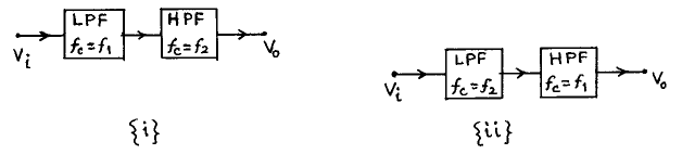
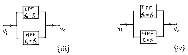
_1.webp)

Start your IIM journey with the right preparation and crack CAT 2026.

Educational materials for JEE preparation

Ask our AI anything

AI can make mistakes. Please verify important information.
AI can make mistakes. Please verify important information.
 91- 6303239042
