Join Our JEE Preparation Group
Prep with like-minded aspirants; Get access to free daily tests and study material.
Sign in
Please select an account to continue using cracku.in
↓ →
Join Our JEE Preparation Group
Prep with like-minded aspirants; Get access to free daily tests and study material.
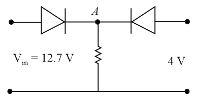
Both the diodes used in the circuit shown are assumed to be ideal and have negligible resistance when these are forward biased. Built in potential in each diode is $$0.7V$$. For the input voltages shown in the figure, the voltage (in Volts) at point A is ___________.
Correct Answer: 12
Assume the left diode is forward-biased and the right diode is reverse-biased: $$V_A = V_{\text{in}} - V_{\text{barrier}} = 12.7 - 0.7 = 12\text{ V}$$
Check biasing state of the right diode: $$\text{Anode potential} = 4\text{ V}$$
$$\text{Cathode potential } (V_A) = 12\text{ V}$$
$$V_{\text{anode}} < V_{\text{cathode}} \implies \text{Reverse-biased (Open circuit)}$$
The initial assumption is consistent.
Create a FREE account and get:
_1.webp)

Educational materials for JEE preparation

Ask our AI anything

AI can make mistakes. Please verify important information.
AI can make mistakes. Please verify important information.