A particle having charge $$10^{-9}$$ C moving in the x-y plane in fields of $$0.4\hat{j}$$ N/C and $$4 \times 10^{-3}\hat{k}$$ T experiences a force of $$(4\hat{i} + 2\hat{j}) \times 10^{-10}$$ N. The velocity of the particle at that instant is :
JEE Magnetic Effects of Current Questions
The net Lorentz force on a charged particle is given by
$$\mathbf{F}=q\left(\mathbf{E}+\mathbf{v}\times\mathbf{B}\right)$$
Given data:
Charge $$q = 10^{-9}\,{\rm C}$$
Electric field $$\mathbf{E}=0.4\,\hat{\jmath}\,{\rm N\,C^{-1}}$$
Magnetic field $$\mathbf{B}=4\times10^{-3}\,\hat{k}\,{\rm T}$$
Force $$\mathbf{F}=(4\hat{\imath}+2\hat{\jmath})\times10^{-10}\,{\rm N}$$
Let the velocity in the x-y plane be $$\mathbf{v}=v_x\hat{\imath}+v_y\hat{\jmath}$$. Its cross-product with $$\mathbf{B}$$ (which is along $$\hat{k}$$) is
$$\mathbf{v}\times\mathbf{B}=(v_x\hat{\imath}+v_y\hat{\jmath})\times(B\hat{k})$$ $$\qquad =B\bigl(v_y\hat{\imath}-v_x\hat{\jmath}\bigr)$$ Substituting $$B=4\times10^{-3}\,{\rm T}$$,
$$\mathbf{v}\times\mathbf{B}=4\times10^{-3}\bigl(v_y\hat{\imath}-v_x\hat{\jmath}\bigr).$$
Add the electric field: $$\mathbf{E}+\mathbf{v}\times\mathbf{B}=0.4\hat{\jmath}+4\times10^{-3}(v_y\hat{\imath}-v_x\hat{\jmath}).$$
Now apply $$\mathbf{F}=q(\mathbf{E}+\mathbf{v}\times\mathbf{B})$$ component-wise.
i-component: $$q\,(4\times10^{-3}v_y)=4\times10^{-10}$$ $$\Rightarrow (10^{-9})(4\times10^{-3})v_y=4\times10^{-10}$$ $$\Rightarrow 4\times10^{-12}v_y=4\times10^{-10}$$ $$\Rightarrow v_y=100\,{\rm m/s}.$$
j-component: $$q\left(0.4-4\times10^{-3}v_x\right)=2\times10^{-10}$$ $$\Rightarrow (10^{-9})\left(0.4-4\times10^{-3}v_x\right)=2\times10^{-10}$$ $$\Rightarrow 0.4-4\times10^{-3}v_x=0.2$$ $$\Rightarrow 4\times10^{-3}v_x=0.2$$ $$\Rightarrow v_x=\frac{0.2}{4\times10^{-3}}=50\,{\rm m/s}.$$
Therefore $$\mathbf{v}=50\hat{\imath}+100\hat{\jmath}\;{\rm m/s}.$$
Option A which is: $$50\hat{\imath}+100\hat{\jmath}\;{\rm m/s}$$
A current carrying solenoid is placed vertically and a particle of mass m with charge Q is released from rest. The particle moves along the axis of solenoid. lf g is acceleration due to gravity then the acceleration (n) of the charged particle will satisfy :
A charged particle moves along the axis of a solenoid. The magnetic field inside a solenoid is along the axis. A particle moving along the axis has velocity parallel to B, so the magnetic force $$\vec{F} = Q\vec{v} \times \vec{B} = 0$$.
Only gravity acts: $$a = g$$.
The answer is Option 4: $$a = g$$.
The current passing through a conducting loop in the form of equilateral triangle of side $$4\sqrt{3}$$ cm is 2A. The magnetic field at its centroid is $$\alpha\times10^{-5}T.$$ The value of $$\alpha$$ is______.
(Given :$$\mu_{o}=4\pi\times 10^{-7} SI$$ units)
B at centroid is sum of B from each straight wire (side of triangle) of triangle. As direction of B from all three wires is same.
Calculate B from a single side, 3B is the required answer
B = $$\frac{\mu_0 I}{4 \pi r} (\sin \theta_1 + \sin \theta_2) $$
Substitute the values $$\theta_1$$=$$\theta_2$$=60, you obtain
B=$$\sqrt{3}$$
$$B_{net}$$=$$3\sqrt{3}$$
An infinitely long straight wire carrying current I is bent in a planer shape as shown in the diagram. The radius of the circular part is r. The magnetic field at the centre O of the circular loop is :
Split the question into two parts: $$ \vec{B}$$ at point O by infinitely long wire and by circular loop.
for straight wire :
$$ \vec{B}_1 = \frac{\mu_0 I}{2\pi r} \hat{i} $$
By the Right-Hand Rule,the magnetic field at O points outward, in the +x direction ($$\hat{i}$$)
for circuar loop :$$ \vec{B}_2 = \frac{\mu_0 I}{2r} (-\hat{i}) = -\frac{\mu_0 I}{2r} \hat{i} $$
According to the Right-Hand Rule for circular loops, the magnetic field at the centre points
inward, into the page, which is the −x direction ($$-\hat{i}$$)
The total magnetic field at the centre $$O$$ is the vector sum of $$\vec{B}_1$$ and $$\vec{B}_2$$:
$$ \vec{B}_{\text{net}} = \vec{B}_1 + \vec{B}_2 $$
$$ \vec{B}_{\text{net}} = \frac{\mu_0 I}{2\pi r} \hat{i} - \frac{\mu_0 I}{2r} \hat{i} $$
Taking $$\frac{\mu_0 I}{2r}$$ as a common factor:
$$ \vec{B}_{\text{net}} = \frac{\mu_0 I}{2r} \left( \frac{1}{\pi} - 1 \right) \hat{i} $$
The magnetic field at the centre of a current carrying circular loop of radius R is $$16\mu T$$. The magnetic field at a distance $$x = \sqrt{3}R$$ on its axis from the centre is______$$\mu T$$.
Two identical circular loops P and Q each of radius r are lying in parallel planes such that they have common axis. The current through P and Q are I and 4I respectively in clockwise direction as seen from 0 . The net magnetic field at O is:

A long cylindrical conductor with large cross section carries an electric current distributed uniformly over its cross-section. Magnetic field due to this current is:
A. maximum at either ends of the conductor and minimum at the midpoint
B. maximum at the axis of the conductor
C. minimum at the surface of the conductor
D. minimum at the axis of the conductor
E. same at all points in the cross-section of the conductor
Choose the correct answer from the options given below :
A long cylindrical conductor carries current uniformly distributed over its cross-section. We need to determine where the magnetic field is minimum.
For a long cylindrical conductor of radius $$R$$ carrying total current $$I$$:
Inside the conductor ($$r < R$$):
$$B(2\pi r) = \mu_0 \cdot \frac{I}{\pi R^2} \cdot \pi r^2 = \mu_0 I \frac{r^2}{R^2}$$
$$B = \frac{\mu_0 I r}{2\pi R^2}$$
The field increases linearly with $$r$$ inside the conductor.
Outside the conductor ($$r > R$$):
$$B = \frac{\mu_0 I}{2\pi r}$$
The field decreases as $$1/r$$ outside.
At the axis ($$r = 0$$): $$B = 0$$. This is the minimum.
At the surface ($$r = R$$): $$B = \frac{\mu_0 I}{2\pi R}$$. This is the maximum.
Statement A: Maximum at ends, minimum at midpoint - FALSE (this describes the axial field, not radial).
Statement B: Maximum at axis - FALSE (B = 0 at axis).
Statement C: Minimum at surface - FALSE (maximum at surface).
Statement D: Minimum at axis - TRUE ($$B = 0$$).
Statement E: Same at all points - FALSE.
The correct answer is Option 3: D Only.
A current of 30 A each flows in opposite directions in two conducting wires, placed parallel to each other at a distance of 8 cm. The magnetic field at the mid point between the two wires is __________ $$\mu$$T. ($$\dfrac{\mu_0}{4\pi} = 10^{-7}$$ N/A$$^2$$)
A particle of charge $$q$$ and mass $$m$$ is projected from origin with an initial velocity has $$\vec{v} = \frac{v_0}{\sqrt{2}}\hat{x} + \frac{v_0}{\sqrt{2}}\hat{y}$$.There exists a uniform magnetic field $$\vec{B} = B_0\hat{z}$$ and a space varying electric field $$\vec{E} = E_0 e^{-\lambda x}\hat{x}$$ within the region $$0 \leq x \leq L$$.After travelling a distance such that x-coordinate has changed from $$x=0$$ to $$x=L$$,the change in the kinetic energy is_________.
A current carrying circular loop of radius 2 cm with unit normal $$\hat{n} = \frac{\hat{k} + \hat{i}}{\sqrt{2}}$$ is placed in a magnetic field, $$\vec{B} = B_0(3\hat{i} + 2\hat{k})$$. If $$B_0 = 4 \times 10^{-3}$$ T and current $$I = 100\sqrt{2}$$ A, the torque experienced by the loop is __________ Wb.A. ($$\pi = 3.14$$)
Two identical long current carrying wires are bent into the shapes shown in the following figures. If the magnitude of magnetic fields at the centres P and Q of a semicircular arc are B$$_1$$ and B$$_2$$ respectively, then the ratio $$\frac{B_1}{B_2}$$ is __________.
We need the magnetic fields at the centres P and Q of semicircular arcs in two different wire configurations.
The magnetic field at the centre of a semicircular arc of radius $$r$$ carrying current $$I$$ is:
$$B_{semi} = \frac{\mu_0 I}{4r}$$
The magnetic field due to a semi-infinite straight wire at a perpendicular distance $$d$$ from its end is:
$$B_{wire} = \frac{\mu_0 I}{4\pi d}$$
Also, an important fact: if the observation point lies on the line of the wire (i.e., on the wire's axis extended), the magnetic field from that wire at the point is zero (since $$d\vec{l} \times \hat{r} = 0$$).
Figure (I) -- Field at P:
The wire comes from infinity on the left along the top, goes to the right, makes a semicircular arc of radius $$r$$ (centre P, opening to the right), and returns to the left along the bottom to infinity.
The two straight portions are horizontal, each at a perpendicular distance $$r$$ from P. Neither wire's axis passes through P, so both contribute a non-zero field.
Using the right-hand rule, the semicircular arc (current going clockwise from top to bottom) and both semi-infinite wires all produce a field at P directed into the page.
$$B_1 = \frac{\mu_0 I}{4r} + \frac{\mu_0 I}{4\pi r} + \frac{\mu_0 I}{4\pi r}$$
$$= \frac{\mu_0 I}{4\pi r}(\pi + 1 + 1) = \frac{\mu_0 I}{4\pi r}(\pi + 2)$$
Figure (II) -- Field at Q:
The wire comes horizontally from the right, makes a semicircular arc of radius $$r$$ (centre Q, opening to the right), and then goes vertically downward to infinity.
The horizontal wire is at perpendicular distance $$r$$ from Q, so it contributes $$\frac{\mu_0 I}{4\pi r}$$ (into the page by right-hand rule).
The vertical wire starts from the bottom of the semicircle, which is directly below Q at distance $$r$$. When extended, this wire's axis passes through Q. Therefore, Q lies on the line of the wire, and the magnetic field at Q due to this wire is zero.
$$B_2 = \frac{\mu_0 I}{4r} + \frac{\mu_0 I}{4\pi r} + 0$$
$$= \frac{\mu_0 I}{4\pi r}(\pi + 1)$$
Now we take the ratio:
$$\frac{B_1}{B_2} = \frac{\frac{\mu_0 I}{4\pi r}(\pi + 2)}{\frac{\mu_0 I}{4\pi r}(\pi + 1)} = \frac{\pi + 2}{\pi + 1}$$
Hence, the correct answer is Option A.
Matd1 List - I with List - II.
atd1 List - I with List - II.
List - I List - II
Relation Law
A. $$\oint\overrightarrow{E}.\overrightarrow{dl}=-\frac{d}{dt}\oint\overrightarrow{B}.\overrightarrow{da}$$ I. Ampere's circuital law
B. $$\oint\overrightarrow{B}.\overrightarrow{dl}=\mu_{\circ}\left(I+\epsilon_{\circ}\frac{d\phi_{E}}{dt}\right)$$ II. Faraday's laws of electromagnetic induction
C. $$\oint\overrightarrow{E}.\overrightarrow{da}=\frac{1}{\epsilon_{\circ}}\int_{v}^{} \rho dv$$ III. Ampere - Maxwell law
D. $$\oint\overrightarrow{B}.\overrightarrow{dl}=\mu_{\circ}I$$ IV. Gauss's law of electrostatics
Choose the correct answer from the options given below :
We need to match Maxwell's equations (List I) with their corresponding laws (List II).
$$\oint \vec{E} \cdot \vec{dl} = -\frac{d}{dt}\oint \vec{B} \cdot \vec{da}$$ This is the integral form of Faraday's law of electromagnetic induction — a changing magnetic flux induces an electric field. → II (Faraday's law)
$$\oint \vec{B} \cdot \vec{dl} = \mu_0\left(I + \epsilon_0\frac{d\phi_E}{dt}\right)$$ This is Ampere's law with Maxwell's displacement current correction — magnetic fields are produced by both conduction current and changing electric flux. → III (Ampere-Maxwell law)
$$\oint \vec{E} \cdot \vec{da} = \frac{1}{\epsilon_0}\int_V \rho \, dv$$ This is Gauss's law for electricity — the electric flux through a closed surface equals the enclosed charge divided by $$\epsilon_0$$. → IV (Gauss's law of electrostatics)
$$\oint \vec{B} \cdot \vec{dl} = \mu_0 I$$ This is the original Ampere's circuital law (without the displacement current term). → I (Ampere's circuital law)
The correct answer is Option (3): A-II, B-III, C-IV, D-I.
An insulated wire is wound so that it forms a flat coil with $$N = 200$$ turns. The radius of the innermost turn is $$r_1 = 3$$ cm, and of the outermost turn $$r_2 = 6$$ cm. If 20 mA current flows in it then the magnetic moment will be $$\alpha \times 10^{-2}$$ A·m². The value of $$\alpha$$ is :
The magnetic moment of a planar coil equals the algebraic sum of magnetic moments of its individual turns.
For one circular turn of radius $$r$$ carrying current $$I$$, magnetic moment $$m = I \, A = I \, (\pi r^{2})$$, directed perpendicular to the plane.
The coil here is a tightly wound flat spiral: the radius grows uniformly from $$r_1 = 3 \text{ cm}$$ to $$r_2 = 6 \text{ cm}$$ in $$N = 200$$ turns. If the turns are uniformly spaced in the radial direction, the number of turns per unit radius is$$ \frac{dn}{dr} = \frac{N}{\,r_2 - r_1\,}. $$
Total magnetic moment $$M$$ is obtained by integrating the contribution $$I \pi r^{2}\, dn$$ from $$r_1$$ to $$r_2$$:$$ M = \int_{r_1}^{r_2} I \pi r^{2}\, dn = I \pi \int_{r_1}^{r_2} r^{2}\left(\frac{N}{r_2 - r_1}\right) dr. $$
Carry out the integral:$$ M = \frac{I \pi N}{r_2 - r_1}\left[ \frac{r^{3}}{3} \right]_{r_1}^{r_2} = \frac{I \pi N}{3}\,\frac{r_2^{3} - r_1^{3}}{r_2 - r_1}. $$
Factor the difference of cubes: $$r_2^{3} - r_1^{3} = (r_2 - r_1)(r_2^{2} + r_1 r_2 + r_1^{2})$$. The factor $$r_2 - r_1$$ cancels, giving the compact formula
$$ M = \frac{I \pi N}{3}\left(r_2^{2} + r_1 r_2 + r_1^{2}\right). \quad -(1) $$
Insert the numerical data (convert cm to m):
$$r_1 = 0.03 \text{ m}, \; r_2 = 0.06 \text{ m}, \; N = 200,\; I = 20 \text{ mA} = 0.02 \text{ A}.$$
Compute the bracket in $$(1)$$:
$$
r_2^{2} = 0.06^{2} = 0.0036, \quad
r_1 r_2 = 0.03 \times 0.06 = 0.0018, \quad
r_1^{2} = 0.03^{2} = 0.0009.
$$
Sum $$ = 0.0036 + 0.0018 + 0.0009 = 0.0063.$$
Dividing by 3: $$\frac{0.0063}{3} = 0.0021.$$
Now evaluate $$M$$:
$$
M = I \pi N \times 0.0021
= \bigl(0.02 \times 200\bigr)\pi \times 0.0021
= 4 \times \pi \times 0.0021
\approx 4 \times 3.1416 \times 0.0021
\approx 0.0264 \text{ A·m}^{2}.
$$
Expressing $$M$$ as $$\alpha \times 10^{-2} \text{ A·m}^{2}$$ gives $$\alpha = 2.64.$$ Hence
Option B which is: $$2.64$$
A conducting circular loop of area $$1.0m^{2}$$ is placed perpendicular to a magnetic field which varies as $$B = \sin(100 t)$$ Tesla. If the resistance of the loop is $$100 \Omega$$, then the average thermal energy dissipated in the loop in one period is _______J.
A conducting circular loop of area $$A = 1.0$$ m$$^2$$ is in a magnetic field $$B = \sin(100t)$$ T with resistance $$R = 100 \Omega$$, and we seek the average thermal energy dissipated in one period.
By Faraday’s law, the induced EMF is given by $$ \varepsilon = -\frac{d\Phi}{dt} = -A\frac{dB}{dt} = -1.0 \times \frac{d}{dt}[\sin(100t)] = -100\cos(100t) \text{ V}. $$ The peak EMF is $$\varepsilon_0 = 100$$ V and the angular frequency is $$\omega = 100$$ rad/s.
The instantaneous power dissipated in the resistance can be written as $$ P = \frac{\varepsilon^2}{R} = \frac{100^2 \cos^2(100t)}{100} = 100\cos^2(100t) \text{ W}. $$
Since the time-average of $$\cos^2(\omega t)$$ over a complete period is $$\frac{1}{2}$$, the average power becomes $$ \overline{P} = \frac{\varepsilon_0^2}{2R} = \frac{(100)^2}{2 \times 100} = \frac{10000}{200} = 50 \text{ W}. $$
The period of oscillation is $$ T = \frac{2\pi}{\omega} = \frac{2\pi}{100} \text{ s}. $$ Multiplying the average power by the period gives the energy dissipated in one period as $$ E = \overline{P} \times T = 50 \times \frac{2\pi}{100} = \frac{100\pi}{100} = \pi \text{ J}. $$
The correct answer is Option (3): $$\pi$$ J
A small cube of side 1 mm is placed at the centre of a circular loop of radius 10 cm carrying a current of 2 A. The magnetic energy stored inside the cube is $$\alpha \times 10^{-14}$$ J. The value of $$\alpha$$ is _______.
$$(\mu_0 = 4\pi \times 10^{-7}$$ Tm/A, $$\pi = 3.14)$$
A moving coil galvanometer of resistance $$100\Omega$$ shows a full scale deflection for a current of 1 mA. The value of resistance required to convert this galvanometer into an ammeter, showing full scale deflection for a current of 5 mA, is ____ $$\Omega$$
The galvanometer behaves like a resistor $$R_g = 100\Omega$$ that can carry a maximum (full-scale) current of $$I_g = 1\text{ mA} = 0.001\text{ A}$$. To measure larger currents we connect a small resistance $$R_s$$ in parallel with the galvanometer. This combination is called a shunt-type ammeter.
Let the required full-scale current of the ammeter be $$I = 5\text{ mA} = 0.005\text{ A}$$. When this current enters the parallel combination, part $$I_g$$ flows through the galvanometer and the remainder $$I_s$$ flows through the shunt:
$$I = I_g + I_s$$
Because the galvanometer and the shunt are in parallel, the voltage across each branch is the same:
$$I_g\,R_g = I_s\,R_s$$ $$-(1)$$
From the current relation, the shunt current is
$$I_s = I - I_g = 0.005 - 0.001 = 0.004\text{ A}$$
Substitute $$I_g$$, $$I_s$$ and $$R_g$$ into equation $$-(1)$$ to obtain $$R_s$$:
$$R_s = \frac{I_g\,R_g}{I_s} = \frac{0.001 \times 100}{0.004} = \frac{0.1}{0.004} = 25\Omega$$
Therefore, the resistance that must be connected in parallel with the galvanometer to convert it into an ammeter of full-scale 5 mA is $$25\Omega$$.
Option C is correct.
Three long straight wires carrying current are arranged mutually parallel as shown in the figure. The force experienced by 15 cm length of wire Q is_______.
$$(\mu_{\circ} =4\pi \times 10^{-7} T.m/A)$$
1 $$\mu$$C charge moving with velocity $$\vec{v} = \left(\hat{i} - 2\hat{j} + 3\hat{k}\right)$$ m/s in the region of magnetic field $$\vec{B} = \left(2\hat{i} + 3\hat{j} - 5\hat{k}\right)$$ T. The magnitude of force acting on it is $$\sqrt{\alpha} \times 10^{-6}$$ N. The value of $$\alpha$$ is __________.
The magnetic (Lorentz) force on a moving point charge is given by
$$\vec{F}=q\,\bigl(\vec{v}\times\vec{B}\bigr)$$
Given data:
Charge, $$q = 1\;\mu\text{C} = 1\times10^{-6}\,\text{C}$$
Velocity, $$\vec{v}=1\,\hat{i}-2\,\hat{j}+3\,\hat{k}\;(\text{m s}^{-1})$$
Magnetic field, $$\vec{B}=2\,\hat{i}+3\,\hat{j}-5\,\hat{k}\;(\text{T})$$
First, calculate the cross product $$\vec{v}\times\vec{B}$$.
Using the determinant form:
$$
\vec{v}\times\vec{B} =
\begin{vmatrix}
\hat{i} & \hat{j} & \hat{k}\\
1 & -2 & 3\\
2 & 3 & -5
\end{vmatrix}
$$
Expand the determinant:
$$
\vec{v}\times\vec{B}
= \hat{i}\bigl((-2)(-5) - (3)(3)\bigr)
- \hat{j}\bigl(1(-5) - 3(2)\bigr)
+ \hat{k}\bigl(1\cdot3 - (-2)\cdot2\bigr)
$$
$$
= \hat{i}\bigl(10 - 9\bigr)
- \hat{j}\bigl(-5 - 6\bigr)
+ \hat{k}\bigl(3 + 4\bigr)
$$
$$
= 1\,\hat{i} + 11\,\hat{j} + 7\,\hat{k}
$$
Magnitude of the cross product:
$$
\lvert\vec{v}\times\vec{B}\rvert
= \sqrt{1^{2}+11^{2}+7^{2}}
= \sqrt{1+121+49}
= \sqrt{171}
$$
Therefore, the magnitude of the magnetic force is
$$
F = q\,\lvert\vec{v}\times\vec{B}\rvert
= \bigl(1\times10^{-6}\bigr)\sqrt{171}\;\text{N}
= \sqrt{171}\times10^{-6}\;\text{N}
$$
Comparing with the required form $$\sqrt{\alpha}\times10^{-6}\,\text{N}$$, we have $$\alpha = 171$$.
Hence, the value of $$\alpha$$ is 171.
A 5 mg particle carrying a charge of $$5\pi \times 10^{-6}$$ C is moving with velocity of $$(3\hat{i} + 2\hat{k}) \times 10^{-2}$$ m/s in a region having magnetic field $$\vec{B} = 0.1 \hat{k}$$ Wb/m$$^2$$. It moves a distance of $$a$$ meter along $$\hat{k}$$ when it completes 5 revolutions. The value of $$a$$ is __________.
Velocity has components:
parallel to B (along k):
v∥ = 2 × 10⁻² m/s
perpendicular to B (in i direction):
v⊥ = 3 × 10⁻² m/s
motion is helical
time period:
$$T=\frac{2\pi m}{qB}$$
given:
m = 5 mg = 5 × 10⁻⁶ kg
q = 5π × 10⁻⁶ C
B = 0.1
$$T=\frac{2\pi\times5\times10^{-6}}{5\pi\times10^{-6}\times0.1}=\frac{2}{0.1}=20\text{ s}$$
time for 5 revolutions:
$$t=5T=100\text{ s}$$
distance along k:
$$a=v∥\times t=2\times10^{-2}\times100=2$$
A circular coil of radius 2 cm and 125 turns carries a current of 1 A. The coil is placed in a uniform magnetic field of magnitude 0.4 T. The axis of the coil makes an angle of 30° with the direction of the magnetic field. The torque acting on the coil is $$\alpha \times 10^{-4}$$ N.m. The value of $$\alpha$$ is ______.
($$\pi = 3.14$$)
The magnitude of the torque on a current-carrying loop in a uniform magnetic field is
$$\tau = N I A B \sin\theta$$
where
$$N = 125$$ turns, $$I = 1\ \text{A}$$, $$B = 0.4\ \text{T}$$, $$\theta = 30^{\circ}$$ is the angle between the coil’s axis (normal to its plane) and $$\vec B$$, and $$A$$ is the area of one turn.
First find the area of the circular loop:
Radius $$r = 2\ \text{cm} = 0.02\ \text{m}$$
$$A = \pi r^{2} = 3.14 \times (0.02)^{2} = 3.14 \times 0.0004 = 0.001256\ \text{m}^{2}$$
Substitute all values into the torque formula:
$$\tau = 125 \times 1 \times 0.001256 \times 0.4 \times \sin 30^{\circ}$$
Since $$\sin 30^{\circ} = 0.5$$,
$$\tau = 125 \times 0.001256 \times 0.4 \times 0.5$$
$$\tau = 125 \times 0.0005024 \times 0.5$$
$$\tau = 125 \times 0.0002512$$
$$\tau = 0.0314\ \text{N}\cdot\text{m}$$
Express $$0.0314$$ in the form $$\alpha \times 10^{-4}$$:
$$0.0314 = 3.14 \times 10^{-2} = 314 \times 10^{-4}$$
Hence $$\alpha = 314$$.
Final answer: $$\boxed{314}$$
The charged particle moving in a uniform magnetic field of $$(3\hat{i} + 2\hat{j})$$ T has an acceleration $$\left(4\hat{i} - \frac{x}{2}\hat{j}\right)$$ m/s$$^2$$. The value of $$x$$ is
In a magnetic field, acceleration is perpendicular to the magnetic field:
a ⟂ B ⇒ a · B = 0
Given:
$$B=(3i+2j)$$
$$a=(4i−\frac{x}{2}j)$$
dot product:
$$(4)(3)+\left(\frac{−x}{2}\right)(2)=0$$
12 − x = 0
x = 12
A conducting square loop of side $$L$$, mass $$M$$ and resistance $$R$$ is moving in the $$XY$$ plane with its edges parallel to the $$X$$ and $$Y$$ axes. The region $$y \geq 0$$ has a uniform magnetic field, $$\vec{B} = B_0\hat{k}$$. The magnetic field is zero everywhere else. At time $$t = 0$$, the loop starts to enter the magnetic field with an initial velocity $$v_0 \hat{j}$$ m/s, as shown in the figure. Considering the quantity $$K = \frac{B_0^2 L^2}{RM}$$ in appropriate units, ignoring self-inductance of the loop and gravity, which of the following statements is/are correct:
A positive point charge of $$10^{-8}$$ C is kept at a distance of 20 cm from the center of a neutral conducting sphere of radius 10 cm. The sphere is then grounded and the charge on the sphere is measured. The grounding is then removed and subsequently the point charge is moved a distance of 10 cm further away from the center of the sphere along the radial direction. Taking $$\frac{1}{4\pi\epsilon_0} = 9 \times 10^9$$ Nm$$^2$$/C$$^2$$ (where $$\epsilon_0$$ is the permittivity of free space), which of the following statements is/are correct:
Given: point charge $$q = +10^{-8}\,\text{C}$$ at a distance $$d = 20\,\text{cm} = 0.20\,\text{m}$$ from the centre $$O$$ of a conducting sphere of radius $$R = 10\,\text{cm} = 0.10\,\text{m}$$.
Throughout we use $$k = \dfrac{1}{4\pi\varepsilon_0}=9\times10^9\;\text{N m}^2\!\text{/C}^2$$.
Step 1 : Image-charge data for a charge outside a sphere
For a point charge $$q$$ kept at distance $$d\,(d\gt R)$$ from the centre of a conducting sphere of radius $$R$$:
• An image charge $$q' = -\dfrac{R}{d}\,q$$ is located on the same line at a distance $$b = \dfrac{R^{2}}{d}$$ from the centre.
• The combination $$(q,q')$$ alone makes the potential of the sphere zero (grounded condition).
• If the sphere is isolated (not grounded) and must keep a specified net charge $$Q_{\text{sphere}}$$, an additional charge $$q_c$$ is placed at the centre. $$q_c$$ is fixed by the condition
$$q_c + q' = Q_{\text{sphere}}$$.
The potential of the sphere then becomes a constant
$$V_{\text{sphere}} = k\dfrac{q_c}{R}$$.
Part (A) : Potential before grounding
Initially the sphere is neutral $$(Q_{\text{sphere}}=0)$$ and isolated.
Image charge: $$q' = -\dfrac{R}{d}\,q = -\dfrac{0.10}{0.20}\,10^{-8} = -0.5\times10^{-8} = -5\times10^{-9}\,\text{C}$$.
To keep the sphere neutral, add a central charge
$$q_c = -q' = +5\times10^{-9}\,\text{C}$$.
The potential of the sphere is therefore $$V_{\text{before}} = k\dfrac{q_c}{R} = 9\times10^9 \times\dfrac{5\times10^{-9}}{0.10} = 9\times10^9 \times 5\times10^{-8} = 45\times10^{1} = 450\;\text{V}.$$
Hence Option A is correct.
Part (B) : Charge that flows when the sphere is grounded
On connecting the sphere to earth, its potential must become zero.
That is achieved by removing the central charge $$q_c$$ (ground provides/absorbs charge) so that only $$q'$$ remains on the sphere.
Charge leaving the sphere to the ground $$\;\Delta Q = q_c = +5\times10^{-9}\,\text{C}.$$
Thus $$5\times10^{-9}\,\text{C}$$ of positive charge flows from the sphere to the earth. Option B is correct.
Part (C) : Charge on the isolated sphere after the grounding wire is removed
With the earth connection opened, the induced charge that remains on the sphere equals $$q' = -5\times10^{-9}\,\text{C}$$.
Option C is correct.
Part (D) : Potential after the external charge is shifted to 30 cm
The grounding has already been removed, so the total charge on the sphere stays fixed at
$$Q_{\text{sphere}} = -5\times10^{-9}\,\text{C}.$$
Now the point charge is shifted to $$d_2 = 30\,\text{cm} = 0.30\,\text{m}$$.
New image charge for the new position:
$$q'_2 = -\dfrac{R}{d_2}\,q = -\dfrac{0.10}{0.30}\,10^{-8}
= -\dfrac{1}{3}\times10^{-8} = -3.33\times10^{-9}\,\text{C}.$$
To keep the sphere’s total charge fixed, the central charge becomes $$q_{c2} = Q_{\text{sphere}} - q'_2 = \bigl(-5\times10^{-9}\bigr) - \bigl(-3.33\times10^{-9}\bigr) = -1.67\times10^{-9}\,\text{C}.$$
The potential of the sphere is therefore $$V_{\text{final}} = k\dfrac{q_{c2}}{R} = 9\times10^9 \times\dfrac{-1.67\times10^{-9}}{0.10} \approx -150\;\text{V}.$$
This is neither 300 V nor positive. Hence Option D is incorrect.
Result
Correct statements: Option A, Option B, Option C.
Six infinitely large and thin non-conducting sheets are fixed in configurations I and II. As shown in the figure, the sheets carry uniform surface charge densities which are indicated in terms of $$\sigma_0$$. The separation between any two consecutive sheets is $$1 \, \mu$$m. The various regions between the sheets are denoted as 1, 2, 3, 4 and 5. If $$\sigma_0 = 9 \, \mu$$C/m$$^2$$, then which of the following statements is/are correct:
(Take permittivity of free space $$\epsilon_0 = 9 \times 10^{-12}$$ F/m)
In a moving coil galvanometer, two moving coils $$M_1$$ and $$M_2$$ have the following particulars :
$$R_1 = 5\,\Omega$$, $$N_1 = 15$$, $$A_1 = 3.6 \times 10^{-3}\,\text{m}^2$$, $$B_1 = 0.25\,\text{T}$$
$$R_2 = 7\,\Omega$$, $$N_2 = 21$$, $$A_2 = 1.8 \times 10^{-3}\,\text{m}^2$$, $$B_2 = 0.50\,\text{T}$$
Assuming that torsional constant of the springs are same for both coils, what will be the ratio of voltage sensitivity of $$M_1$$ and $$M_2$$ ?
Voltage sensitivity $$S_V$$ of a moving-coil galvanometer is defined as the deflection produced per unit applied voltage.
If the torsional constant of the suspension spring is $$k$$, then
Current sensitivity $$S_I$$ is $$\displaystyle S_I = \frac{NAB}{k} \quad -(1)$$
where
$$N$$ = number of turns, $$A$$ = area of each turn, $$B$$ = magnetic field.
Voltage sensitivity is obtained by dividing current sensitivity by the total resistance $$R$$ of the coil:
$$\displaystyle S_V = \frac{S_I}{R} = \frac{NAB}{kR} \quad -(2)$$
Because both coils have the same spring, the torsional constant $$k$$ is identical for them and cancels in the ratio.
For coil $$M_1$$:
$$N_1 = 15$$, $$A_1 = 3.6 \times 10^{-3}\,\text{m}^2$$, $$B_1 = 0.25\,\text{T}$$, $$R_1 = 5\,\Omega$$
For coil $$M_2$$:
$$N_2 = 21$$, $$A_2 = 1.8 \times 10^{-3}\,\text{m}^2$$, $$B_2 = 0.50\,\text{T}$$, $$R_2 = 7\,\Omega$$
Using $$-(2)$$ for each coil and taking the ratio:
$$\frac{S_{V1}}{S_{V2}} = \frac{\dfrac{N_1A_1B_1}{kR_1}}{\dfrac{N_2A_2B_2}{kR_2}} = \frac{N_1A_1B_1R_2}{N_2A_2B_2R_1}$$
Substituting the given values:
$$N_1A_1B_1R_2 = 15 \times 3.6\times10^{-3} \times 0.25 \times 7$$
$$= 15 \times 0.0036 \times 0.25 \times 7$$
$$= 0.0945$$
$$N_2A_2B_2R_1 = 21 \times 1.8\times10^{-3} \times 0.50 \times 5$$
$$= 21 \times 0.0018 \times 0.50 \times 5$$
$$= 0.0945$$
Therefore
$$\frac{S_{V1}}{S_{V2}} = \frac{0.0945}{0.0945} = 1$$
Thus, the voltage sensitivities of $$M_1$$ and $$M_2$$ are equal, giving the ratio
$$S_{V1} : S_{V2} = 1 : 1$$
Option A is correct.
List-I shows four configurations, each consisting of a pair of ideal electric dipoles. Each dipole has a dipole moment of magnitude $$p$$, oriented as marked by arrows in the figures. In all the configurations the dipoles are fixed such that they are at a distance $$2r$$ apart along the $$x$$ direction. The midpoint of the line joining the two dipoles is $$X$$. The possible resultant electric fields $$\vec{E}$$ at $$X$$ are given in List-II.
Choose the option that describes the correct match between the entries in List-I to those in List-II.
A long straight wire of a circular cross-section with radius '$$a$$' carries a steady current $$I$$. The current $$I$$ is uniformly distributed across this cross-section. The plot of magnitude of magnetic field B with distance $$r$$ from the centre of the wire is given by

An infinite wire has a circular bend of radius a, and carrying a current I as shown in figure. The magnitude of magnetic field at the origin O of the arc is given by :
An electron projected perpendicular to a uniform magnetic field B moves in a circle. If Bohr's quantization is applicable, then the radius of the electronic orbit in the first excited state is :
When an electron is projected perpendicular to a uniform magnetic field $$B$$, it moves in a circular path due to the magnetic force acting as the centripetal force. The force balance equation is given by:
$$ e v B = \frac{m v^2}{r} $$
where $$e$$ is the charge of the electron, $$v$$ is its speed, $$m$$ is its mass, and $$r$$ is the radius of the circular path. Simplifying this equation:
$$ e B = \frac{m v}{r} $$
Rearranging, we get:
$$ m v = e B r \quad \text{(1)} $$
Bohr's quantization condition states that the angular momentum is quantized and given by:
$$ m v r = n \frac{h}{2\pi} \quad \text{(2)} $$
where $$n$$ is the principal quantum number and $$h$$ is Planck's constant. The first excited state corresponds to $$n = 2$$ (since the ground state is $$n = 1$$). Substituting $$n = 2$$ into equation (2):
$$ m v r = 2 \times \frac{h}{2\pi} = \frac{h}{\pi} \quad \text{(3)} $$
We now have two equations: equation (1) $$m v = e B r$$ and equation (3) $$m v r = \frac{h}{\pi}$$. Substituting equation (1) into equation (3):
$$ (e B r) \times r = \frac{h}{\pi} $$
Simplifying:
$$ e B r^2 = \frac{h}{\pi} $$
Solving for $$r^2$$:
$$ r^2 = \frac{h}{\pi e B} $$
Taking the square root of both sides:
$$ r = \sqrt{\frac{h}{\pi e B}} $$
This is the radius of the electronic orbit in the first excited state. Comparing with the given options, this expression matches option A, $$\sqrt{\frac{h}{\pi eeB}}$$, when interpreted as $$\sqrt{\frac{h}{\pi e B}}$$ (considering "ee" as a typographical error for "e").
Thus, the correct option is A.
Consider a long straight wire of a circular cross-section (radius a) carrying a steady current I. The current is uniformly distributed across this cross-section. The distances from the centre of the wire's cross-section at which the magnetic field [inside the wire, outside the wire] is half of the maximum possible magnetic field, any where due to the wire, will be
Consider a long thin conducting wire carrying a uniform current I. A particle having mass "M" and charge "q" is released at a distance "a" from the wire with a speed $$\epsilon_{\circ}$$ along the direction of current in the wire. The particle gets attracted to the wire due to magnetic force. The particle turns round when it is at distance x from the wire. The value of x is [$$\mu_{\circ}$$ is vacuum permeability]

N equally spaced charges each of value q , are placed on a circle of radius R . The circle rotates about its axis with an angular velocity $$\omega$$ as shown in the figure. A bigger Amperian loop B encloses the whole circle where as a smaller Amperian loop A encloses a small segment. The difference between enclosed currents, $$I_A - I_B$$, for the given Amperian loops is
A plane electromagnetic wave propagates along the +x direction in free space. The components of the electric field, $$\vec{E}$$ and magnetic field, $$\vec{B}$$
vectors associated with the wave in Cartesian frame are
For an electromagnetic wave propagating in the +x direction:
- The electric and magnetic fields must be perpendicular to the direction of propagation (transverse wave)
- $$\vec{E}$$, $$\vec{B}$$, and the propagation direction must form a right-handed coordinate system
Since the wave propagates along +x, neither $$\vec{E}$$ nor $$\vec{B}$$ can have an x-component.
This eliminates Options 1 (has $$E_x$$), 3 (has $$B_y$$ but we need to check), and 4 (has $$B_x$$).
For $$\hat{E} \times \hat{B} = \hat{k}_{propagation} = \hat{x}$$:
$$\hat{y} \times \hat{z} = \hat{x}$$ ✓
So $$E_y, B_z$$ is consistent with propagation along +x.
Check Option 3: $$E_z, B_y$$: $$\hat{z} \times \hat{y} = -\hat{x}$$ (propagation in -x direction). Incorrect.
The correct answer is Option 2: $$E_y, B_z$$.
Figure shows a current carrying square loop ABCD of edge length 'a' lying in a plane. If the resistance of the ABC part is r and that of ADC part is 2r, then the magnitude of the resultant magnetic field at centre of the square loop is
Let $$B_1$$ be the magnitude of magnetic field at center of a circular coil of radius R carrying current I. Let $$B_2$$ be the magnitude of magnetic field at an axial distance 'x' from the center. For $$x : R = 3 : 4$$, $$\frac{B_2}{B_1}$$ is:
For a circular coil of radius $$R$$ carrying current $$I$$, the standard results for magnetic field are:
• At the centre of the coil (on its plane) $$B_1 = \frac{\mu_0 I}{2R} \quad -(1)$$
• On the axis of the coil at a distance $$x$$ from the centre $$B_2 = \frac{\mu_0 I R^{2}}{2\left(R^{2}+x^{2}\right)^{3/2}} \quad -(2)$$
To obtain the required ratio, divide $$(2)$$ by $$(1)$$:
$$\frac{B_2}{B_1} = \frac{\mu_0 I R^{2}}{2\left(R^{2}+x^{2}\right)^{3/2}} \times \frac{2R}{\mu_0 I} = \frac{R^{3}}{\left(R^{2}+x^{2}\right)^{3/2}} \quad -(3)$$
Rewrite $$(3)$$ more compactly:
$$\frac{B_2}{B_1} = \left(\frac{R^{2}}{R^{2}+x^{2}}\right)^{3/2} \quad -(4)$$
The problem specifies $$x : R = 3 : 4$$, so choose $$x = 3k$$ and $$R = 4k$$ for some constant $$k$$.
Substitute these into $$(4)$$:
$$\frac{B_2}{B_1} = \left( \frac{(4k)^{2}}{(4k)^{2} + (3k)^{2}} \right)^{3/2} = \left( \frac{16k^{2}}{16k^{2} + 9k^{2}} \right)^{3/2} = \left( \frac{16}{25} \right)^{3/2} \quad -(5)$$
Evaluate the power:
$$\left( \frac{16}{25} \right)^{3/2} = \frac{16^{3/2}}{25^{3/2}} = \frac{( \sqrt{16} )^{3}}{( \sqrt{25} )^{3}} = \frac{4^{3}}{5^{3}} = \frac{64}{125}$$
Hence, $$\displaystyle \frac{B_2}{B_1} = \frac{64}{125}$$, or in ratio form $$64 : 125$$.
Therefore, the correct option is Option C (64 : 125).
Given below are two statements. One is labelled as Assertion (A) and the other is labelled as Reason (R). Assertion (A) : A electron in a certain region of uniform magnetic field is moving with constant velocity in a straight line path. Reason (R): The magnetic field in that region is along the direction of velocity of the electron. In the light of the above statements, choose the correct answer from the options given below :
Assertion (A): An electron moves with constant velocity in a straight line in a uniform magnetic field.
The magnetic force on a moving charge is $$\vec{F} = q\vec{v} \times \vec{B}$$. If $$\vec{v} \parallel \vec{B}$$, then $$\vec{v} \times \vec{B} = 0$$ and the force is zero, so the electron moves in a straight line with constant velocity. TRUE.
Reason (R): The magnetic field is along the direction of velocity of the electron.
This is exactly the condition that makes the cross product zero. TRUE.
R correctly explains A: when $$\vec{B} \parallel \vec{v}$$, there is no magnetic force, so the electron travels in a straight line.
The correct answer is Option C: Both (A) and (R) are true and (R) is the correct explanation of (A).
Given below are two statements:one is labelled as Assertion A and the other is labelled as Reason R.
Assertion A: If oxygen ion ($$O^{-2}$$) and Hydrogen ion ($$H^+$$) enter normal to the magnetic field with equal momentum, then the path of $$O^{-2}$$ ion has a smaller curvature than that of $$H^+$$.
Reason R: A proton with same linear momentum as an electron will form a path of smaller radius of curvature on entering a uniform magnetic field perpendicularly.
In the light of the above statement,Choose the correct answer from the options given below.
When a charged particle of charge $$q$$ and linear momentum $$p$$ enters a uniform magnetic field $$\mathbf{B}$$ perpendicular to the field, the magnetic force $$|q|vB$$ provides the required centripetal force $$\dfrac{mv^{2}}{r}$$.
Substituting $$p = mv$$ and $$v = \dfrac{p}{m}$$, the radius (called radius of curvature) is obtained as
$$r = \dfrac{p}{|q|B}$$ $$-(1)$$
Case 1: Oxide ion $$O^{2-}$$ versus proton $$H^{+}$$
For $$O^{2-}: |q| = 2e \quad(\text{two electronic charges})$$
For $$H^{+}: |q| = e$$
Both ions are given to have the same momentum $$p$$ and the same field $$B$$, so using $$(1)$$:
$$r_{O^{2-}} = \dfrac{p}{2eB}, \qquad r_{H^{+}} = \dfrac{p}{eB} = 2\,r_{O^{2-}}$$
Thus $$r_{O^{2-}} \lt r_{H^{+}}$$, i.e. the oxide ion describes a circle of smaller radius (larger bending) than the proton. Consequently its curvature radius is smaller. Hence Assertion A is correct.
Case 2: Proton versus electron with the same linear momentum
For a proton $$|q_p| = e$$ and for an electron $$|q_e| = e$$. With equal momenta $$p$$, equation $$(1)$$ gives
$$r_p = \dfrac{p}{eB}, \qquad r_e = \dfrac{p}{eB}$$
The radii are identical; the proton does not form a path of smaller radius than the electron. Therefore Reason R is false.
Conclusion: Assertion A is true, Reason R is false. The correct choice is Option A.
A current of $$5\,A$$ exists in a square loop of side $$\frac{1}{\sqrt{2}}\,m.$$ Then the magnitude of the magnetic field $$B$$ at the centre of the square loop will be $$p \times10^{-6}\,T,$$ where value of $$p$$ is $$\underline{\hspace{2cm}}.$$ $$\left[\mu_0=4\pi\times10^{-7}\,TmA^{-1}\right] $$
The magnetic field at the centre of a square loop carrying current can be found by applying the Biot-Savart law to one side and then using symmetry. Given that I = 5 A, a = 1/√2 m and μ₀ = 4π×10⁻⁷ T m A⁻¹, consider a single straight segment of the loop. For a finite straight wire the field at a perpendicular distance d, subtending angles θ₁ and θ₂ at the observation point, is $$B_{\text{wire}} = \frac{\mu_0 I}{4\pi d}(\sin\theta_1 + \sin\theta_2).$$ In our square loop the distance from the centre to each side is d = a/2, and each side subtends equal angles θ₁ = θ₂ = 45° at the centre. Substituting these values gives $$B_1 = \frac{\mu_0 I}{4\pi\,(a/2)}\bigl(\sin45°+\sin45°\bigr) = \frac{\mu_0 I}{2\pi a}\times\frac{2}{\sqrt2} = \frac{\sqrt2\,\mu_0 I}{2\pi a}.$$ By symmetry all four sides contribute equally and their fields add in the same direction, so the total field is $$B = 4B_1 = 4\;\frac{\sqrt2\,\mu_0 I}{2\pi a} = \frac{2\sqrt2\,\mu_0 I}{\pi a}.$$ Substituting I = 5 A, a = 1/√2 m and μ₀ = 4π×10⁻⁷ T m A⁻¹ yields $$B = \frac{2\sqrt2\times4\pi\times10^{-7}\times5}{\pi\times(1/\sqrt2)}.$$ The π factors cancel, giving $$B = \frac{2\sqrt2\times4\times5\times10^{-7}}{1/\sqrt2} = 40\sqrt2\times10^{-7}\times\sqrt2 = 40\times2\times10^{-7} = 8\times10^{-6}\text{ T}.$$ Therefore, the magnetic field at the centre of the square loop is $$B = 8\times10^{-6}\text{ T},$$ and the required value of p is 8.
A particle of charge 1.6 $$\mu$$C and mass 16 $$\mu$$g is present in a strong magnetic field of $$6.28 T$$. The particle is then fired perpendicular to magnetic field. The time required for the particle to return to original location for the first time is ______ s. ($$\pi = 3.14$$)
When a charged particle is fired perpendicular to a uniform magnetic field, it traces a circular path. The time required for the particle to return to its original location for the first time is exactly the time period of this circular motion.
The magnetic force provides the centripetal force: $$qvB = \frac{mv^{2}}{r}$$
This gives the radius $$r = \frac{mv}{qB}$$.
The time period is $$T = \frac{2\pi r}{v} = \frac{2\pi m}{qB}$$
The time period does not depend on the speed of the particle.
Substituting into the time period formula:
$$T = \frac{2 \times 3.14 \times 16 \times 10^{-6}}{1.6 \times 10^{-6} \times 6.28}$$
$$T = \frac{100.48 \times 10^{-6}}{10.048 \times 10^{-6}} = \frac{100.48}{10.048} = 10 \text{ s}$$
So, the answer is $$10$$.
A proton is moving undeflected in a region of crossed electric and magnetic fields at a constant speed of $$2 \times 10^{5} ms^{-1}$$. When the electric field is switched off, the proton moves along a circular path of radius 2 cm .The magnitude of electric field is $$x\times 10^{4} N/C$$. The value of x is________Take the mass of the proton $$1.6\times 10^{-27}kg$$
We are told a proton moves undeflected in crossed electric and magnetic fields at $$v = 2 \times 10^5$$ m/s. When the electric field is switched off, the proton moves in a circle of radius $$r = 2$$ cm. We need to find the electric field.
Condition for undeflected motion in crossed fields
When a charged particle moves undeflected through crossed electric and magnetic fields, the electric force and magnetic force balance each other:
$$qE = qvB$$
$$E = vB \quad \ldots (1)$$
Find $$B$$ from the circular motion when $$E$$ is switched off
When the electric field is switched off, only the magnetic force acts, providing the centripetal force for circular motion:
$$qvB = \frac{mv^2}{r}$$
$$B = \frac{mv}{qr} \quad \ldots (2)$$
Substituting given values ($$m = 1.6 \times 10^{-27}$$ kg, $$v = 2 \times 10^5$$ m/s, $$q = 1.6 \times 10^{-19}$$ C, $$r = 2$$ cm $$= 0.02$$ m):
$$B = \frac{1.6 \times 10^{-27} \times 2 \times 10^5}{1.6 \times 10^{-19} \times 0.02}$$
$$B = \frac{3.2 \times 10^{-22}}{3.2 \times 10^{-21}} = \frac{1}{10} = 0.1 \text{ T}$$
Calculate the electric field using equation (1)
$$E = vB = 2 \times 10^5 \times 0.1 = 2 \times 10^4 \text{ N/C}$$
Therefore, $$x = 2$$.
The answer is 2.
The magnetic field inside a 200 turns solenoid of radius 10 cm is 2.9 $$\times$$ $$10^{-4}$$ Tesla . If the solenoid carries a current of 0.29 A , then the length of the solenoid is ________ $$\pi$$ cm.
The magnetic field inside a solenoid is given by:
$$ B = \mu_0 n I = \mu_0 \frac{N}{L} I $$
We are given that $$B = 2.9 \times 10^{-4}$$ T, $$N = 200$$, $$I = 0.29$$ A, and $$\mu_0 = 4\pi \times 10^{-7}$$ T·m/A.
We rearrange this formula to solve for $$L$$:
$$ L = \frac{\mu_0 N I}{B} = \frac{4\pi \times 10^{-7} \times 200 \times 0.29}{2.9 \times 10^{-4}} $$
It follows that
$$ L = \frac{4\pi \times 10^{-7} \times 58}{2.9 \times 10^{-4}} = \frac{4\pi \times 58 \times 10^{-7}}{2.9 \times 10^{-4}} $$
Simplifying further gives
$$ = \frac{4\pi \times 20 \times 10^{-7}}{10^{-4}} = 4\pi \times 20 \times 10^{-3} = 80\pi \times 10^{-3} \text{ m} $$
Finally,
$$ = 8\pi \text{ cm} $$
Therefore, the answer is 8.
A 4.0 cm long straight wire carrying a current of 8A is placed perpendicular to an uniform magnetic field of strength 0.15 T. The magnetic force on the wire is _________ mN.
The magnetic force $$F$$ on a straight conductor of length $$l$$ carrying current $$I$$ in a uniform magnetic field of magnitude $$B$$ is given by the formula
$$F = I\,l\,B\,\sin\theta$$,
where $$\theta$$ is the angle between the direction of current and the magnetic field.
Here the wire is placed perpendicular to the field, so $$\theta = 90^{\circ}$$ and $$\sin 90^{\circ} = 1$$. Thus,
$$F = I\,l\,B$$ $$-(1)$$
Convert the length from centimetres to metres:
$$l = 4.0\ \text{cm} = 4.0 \times 10^{-2}\ \text{m} = 0.04\ \text{m}$$
Substitute $$I = 8\ \text{A}$$, $$l = 0.04\ \text{m}$$ and $$B = 0.15\ \text{T}$$ into $$(1)$$:
$$F = 8 \times 0.04 \times 0.15$$
First multiply $$8 \times 0.04 = 0.32$$.
Then multiply $$0.32 \times 0.15 = 0.048$$.
So, $$F = 0.048\ \text{N}$$.
To express the force in milli-newtons (1 mN = $$10^{-3}$$ N):
$$0.048\ \text{N} = 0.048 \times 10^{3}\ \text{mN} = 48\ \text{mN}$$.
Therefore, the magnetic force acting on the wire is $$\mathbf{48\ mN}$$.
A loop ABCDA, carrying current $$I = 12$$ A, is placed in a plane, consists of two semi-circular segments of radius $$R_1 = 6\pi$$ m and $$R_2 = 4\pi$$ m. The magnitude of the resultant magnetic field at center O is $$k \times 10^{-7}$$ T. The value of k is __________.
(Given $$\mu_0 = 4\pi \times 10^{-7}$$ Tm A$$^{-1}$$)
A tightly wound long solenoid carries a current of $$1.5\,A.$$ An electron is executing uniform circular motion inside the solenoid with a time period of $$75\,ns.$$ The number of turns per metre in the solenoid is $$\underline{\hspace{1cm}}.$$ [Take mass of electron $$m_e=9\times10^{-31}\,kg,$$ change of electron $$|q_e|=1.6\times10^{-19}\,$$ $$C,$$ $$\mu_0=4\pi\times10^{-7}\,N$$ $$A^{-2},\,1\,ns=10^{-9}\,s]$$
Two long parallel wires X and Y, separated by a distance of 6 cm , carry currents of 5A and 4A, respectively, in opposite directions as shown in the figure. Magnitude of the resultant magnetic field at point P at a distance of 4 cm from wire Y is $$x \times 10^{-5}T$$. The value of is__________ . Take permeability of free space as
$$\mu_{\circ}=4\pi \times 10^{-7}$$SI units.
$$I_X = 5 \text{ A}$$
$$I_Y = 4 \text{ A}$$
Distance between wires X and Y is $$6 \text{ cm}$$
Point P is at a distance of $$4 \text{ cm}$$ to the right of wire Y.
The total distance of point P from wire X is:
$$ r_X = 6 \text{ cm} + 4 \text{ cm} = 10 \text{ cm} = 0.1 \text{ m} $$
The distance of point P from wire Y is:
$$ r_Y = 4 \text{ cm} = 0.04 \text{ m} $$
The magnetic field due to a long straight wire is given by the formula:
$$ B = \frac{\mu_0 I}{2\pi r} $$
Calculate the magnetic field at point P due to wire X ($$B_X$$):
$$ B_X = \frac{4\pi \times 10^{-7} \times 5}{2\pi \times 0.1} $$
$$ B_X = \frac{2 \times 10^{-7} \times 5}{0.1} $$
$$ B_X = 10 \times 10^{-6} \text{ T} = 1 \times 10^{-5} \text{ T} $$
By the right-hand grip rule, with current flowing upwards, the direction of $$B_X$$ at point P is into the plane of the paper.
Calculate the magnetic field at point P due to wire Y ($$B_Y$$):
$$ B_Y = \frac{4\pi \times 10^{-7} \times 4}{2\pi \times 0.04} $$
$$ B_Y = \frac{2 \times 10^{-7} \times 4}{0.04} $$
$$ B_Y = 2 \times 10^{-5} \text{ T} $$
By the right-hand grip rule, with current flowing downwards, the direction of $$B_Y$$ at point P is out of the plane of the paper.
Since the magnetic fields are in opposite directions, the resultant magnetic field ($$B_{net}$$) is the difference between their magnitudes:
$$ B_{net} = B_Y - B_X $$
$$ B_{net} = 2 \times 10^{-5} \text{ T} - 1 \times 10^{-5} \text{ T} $$
$$ B_{net} = 1 \times 10^{-5} \text{ T} $$
Comparing this with the given expression $$x \times 10^{-5} \text{ T}$$, we get the value of $$x$$:
$$ x = 1 $$
To find the spring constant $$(k)$$ of a spring experimentally, a student commits 2% positive error in the measurement of time and 1% negative error in measurement of mass. The percentage error in determining value of $$k$$ is :
Find percentage error in spring constant $$k$$ given 2% error in time and 1% error in mass.
Relation between k, m, and T.
$$T = 2\pi\sqrt{\frac{m}{k}}$$, so $$k = \frac{4\pi^2 m}{T^2}$$.
Error propagation.
$$\frac{\Delta k}{k} = \frac{\Delta m}{m} + 2\frac{\Delta T}{T} = 1\% + 2(2\%) = 1\% + 4\% = 5\%$$
Note: we take absolute values of errors for maximum percentage error regardless of sign.
The correct answer is Option A: 5%.
A proton and a deutron ($$q = +e, m = 2.0u$$) having same kinetic energies enter a region of uniform magnetic field $$\vec{B}$$, moving perpendicular to $$\vec{B}$$. The ratio of the radius of deutron path to the radius of the proton path is:
A proton and a deuteron with the same kinetic energy enter a uniform magnetic field perpendicular to $$\vec{B}$$. We need the ratio of their radii of circular paths.
When a charged particle moves perpendicular to a magnetic field, it follows a circular path with radius:
$$ r = \frac{mv}{qB} $$
Since $$KE = \frac{1}{2}mv^2$$, we get $$mv = \sqrt{2m \cdot KE}$$. Therefore:
$$ r = \frac{\sqrt{2m \cdot KE}}{qB} $$
For the proton: mass = $$m_p$$, charge = $$e$$, so $$r_p = \frac{\sqrt{2m_p \cdot KE}}{eB}$$
For the deuteron: mass = $$2m_p$$ (approximately twice the proton mass), charge = $$e$$ (same charge as proton), so:
$$ r_d = \frac{\sqrt{2 \cdot 2m_p \cdot KE}}{eB} = \frac{\sqrt{2} \cdot \sqrt{2m_p \cdot KE}}{eB} = \sqrt{2} \cdot r_p $$
The ratio is:
$$ \frac{r_d}{r_p} = \sqrt{2} : 1 $$
The correct answer is Option (1): $$\sqrt{2} : 1$$.
Match List I with List II

Choose the correct answer from the options given below
A current of 200 $$\mu$$A deflects the coil of a moving coil galvanometer through 60°. The current to cause deflection through $$\frac{\pi}{10}$$ radian is
{image}
A square loop of side $$15 \text{ cm}$$ being moved towards right at a constant speed of $$2 \text{ cm/s}$$ as shown in figure. The front edge enters the $$50 \text{ cm}$$ wide magnetic field at $$t = 0$$. The value of induced emf in the loop at $$t = 10 \text{ s}$$ will be :
Side of square loop,
$$a=15\ \text{cm}$$
Speed of loop,
$$v=2\ \text{cm s}^{-1}$$
Time taken by the complete loop to enter the magnetic field:
$$t=\frac{15}{2}=7.5\ \text{s}$$
Since,
$$10\ \text{s} > 7.5\ \text{s}$$
the complete loop is inside the magnetic field at t=10 s.
Therefore, magnetic flux linked with the loop does not change.
$$e=\frac{d\phi}{dt}$$
Since,
$$\frac{d\phi}{dt}=0$$
Hence,
$$\boxed{e=0}$$
Match List-I with List-II :

Choose the correct answer from the options given below :
A galvanometer has a resistance of $$50\ \Omega$$ and it allows maximum current of $$5$$ mA. It can be converted into voltmeter to measure upto $$100$$ V by connecting in series a resistor of resistance.
Convert a galvanometer (resistance 50 $$\Omega$$, max current 5 mA) into a voltmeter reading up to 100 V.
A galvanometer measures current. To use it as a voltmeter, we connect a high resistance in series so that when the full voltage is applied, only the maximum safe current flows through the galvanometer.
By Ohm’s law, when $$V = 100$$ V is applied and maximum current $$I_g = 5$$ mA = $$5 \times 10^{-3}$$ A flows:
$$ R_{\text{total}} = \frac{V}{I_g} = \frac{100}{5 \times 10^{-3}} = \frac{100}{0.005} = 20000 \text{ } \Omega $$
Subtracting the galvanometer resistance of 50 $$\Omega$$ gives the required series resistance:
$$ R_{\text{series}} = R_{\text{total}} - R_g = 20000 - 50 = 19950 \text{ } \Omega $$
The correct answer is Option C: 19950 $$\Omega$$.
A long straight wire of radius a carries a steady current I. The current is uniformly distributed across its cross section. The ratio of the magnetic field at $$\frac{a}{2}$$ and $$2a$$ from axis of the wire is :
We need to find the ratio of the magnetic field at distances $$\frac{a}{2}$$ and $$2a$$ from the axis of a long straight wire of radius $$a$$ carrying a steady, uniformly distributed current $$I$$.
Recall that Ampere's law states: $$\oint \vec{B} \cdot d\vec{l} = \mu_0 I_{enc}$$ where $$I_{enc}$$ is the current enclosed by the Amperian loop.
Inside the wire at a distance $$r$$ from the axis, the current is uniformly distributed over the cross-section of radius $$a$$. The enclosed current is proportional to the enclosed area: $$I_{enc} = I \cdot \frac{\pi r^2}{\pi a^2} = I \cdot \frac{r^2}{a^2}$$.
Applying Ampere's law with a circular Amperian loop of radius $$r$$ gives $$B \cdot 2\pi r = \mu_0 \cdot I \cdot \frac{r^2}{a^2}$$, so $$B_{inside} = \frac{\mu_0 I r}{2\pi a^2}$$. At $$r = \frac{a}{2}$$, this becomes $$B_1 = \frac{\mu_0 I \cdot \frac{a}{2}}{2\pi a^2} = \frac{\mu_0 I}{4\pi a}$$.
Outside the wire at a distance $$r$$ from the axis, the entire current $$I$$ is enclosed, so Ampere's law gives $$B \cdot 2\pi r = \mu_0 I$$ and hence $$B_{outside} = \frac{\mu_0 I}{2\pi r}$$. At $$r = 2a$$, this becomes $$B_2 = \frac{\mu_0 I}{2\pi \cdot 2a} = \frac{\mu_0 I}{4\pi a}$$.
The ratio of these fields is $$\frac{B_1}{B_2} = \frac{\frac{\mu_0 I}{4\pi a}}{\frac{\mu_0 I}{4\pi a}} = \frac{1}{1}$$, so $$B_1 : B_2 = 1 : 1$$.
The correct answer is Option (2): 1 : 1.
A proton moving with a constant velocity passes through a region of space without any change in its velocity. If $$\vec{E}$$ and $$\vec{B}$$ represent the electric and magnetic fields respectively, then the region of space may have :
(A) $$E = 0, B = 0$$; (B) $$E = 0, B \neq 0$$; (C) $$E \neq 0, B = 0$$; (D) $$E \neq 0, B \neq 0$$. Choose the most appropriate answer from the options given below :
A proton moves with constant velocity, meaning the net force on it is zero.
(A) $$E = 0, B = 0$$: No force, proton moves at constant velocity. Possible.
(B) $$E = 0, B \neq 0$$: If the proton moves parallel to $$\vec{B}$$, the magnetic force $$q\vec{v} \times \vec{B} = 0$$. Possible.
(C) $$E \neq 0, B = 0$$: The electric force $$q\vec{E} \neq 0$$, so the proton would accelerate. Not possible.
(D) $$E \neq 0, B \neq 0$$: If $$q\vec{E} + q\vec{v} \times \vec{B} = 0$$, the electric and magnetic forces can cancel. Possible.
The correct options are (A), (B) and (D) only, which corresponds to Option (3).
A uniform magnetic field of $$2 \times 10^{-3}$$ T acts along positive Y-direction. A rectangular loop of sides 20 cm and 10 cm with current of 5 A is in Y-Z plane. The current is in anticlockwise sense with reference to negative X axis. Magnitude and direction of the torque is:
Magnetic field $$B = 2 \times 10^{-3}$$ T along +Y. Rectangular loop 20 cm × 10 cm in Y-Z plane, current 5 A anticlockwise w.r.t. negative X-axis.
The area vector of the loop in Y-Z plane points along $$\pm\hat{x}$$. Since current is anticlockwise when viewed from negative X-axis, by the right-hand rule, the area vector points along $$-\hat{x}$$.
$$\vec{m} = I\vec{A} = 5 \times (20 \times 10 \times 10^{-4})(-\hat{x}) = 5 \times 0.02(-\hat{x}) = -0.1\hat{x}$$ A m$$^2$$.
Torque: $$\vec{\tau} = \vec{m} \times \vec{B} = (-0.1\hat{x}) \times (2 \times 10^{-3}\hat{y})$$
$$= -0.1 \times 2 \times 10^{-3}(\hat{x} \times \hat{y}) = -2 \times 10^{-4}\hat{z}$$
Magnitude: $$2 \times 10^{-4}$$ N m, direction: along negative Z-direction.
The correct answer is Option B: $$2 \times 10^{-4}$$ N m along negative Z-direction.
An element $$\Delta l = \Delta x\hat{i}$$ is placed at the origin and carries a large current $$I = 10 \text{ A}$$. The magnetic field on the $$y$$-axis at a distance of $$0.5 \text{ m}$$ from the element of length $$\Delta x$$ of $$1 \text{ cm}$$ is:
Match List I with List II

Choose the correct answer from the options given below:
Paramagnetic substances: A. align themselves along the directions of external magnetic field. B. attract strongly towards external magnetic field. C. has susceptibility little more than zero. D. move from a region of strong magnetic field to weak magnetic field. Choose the most appropriate answer from the options given below:
The electrostatic force $$(\vec{F_1})$$ and magnetic force $$(\vec{F_2})$$ acting on a charge $$q$$ moving with velocity $$v$$ can be written :
This question asks for the correct expressions for the electrostatic force and magnetic force acting on a charge $$q$$ moving with velocity $$\vec{v}$$.
Recall that the electrostatic force on a charge $$q$$ in an electric field $$\vec{E}$$ is given by:
$$\vec{F_1} = q\vec{E}$$
This force acts in the direction of $$\vec{E}$$ for a positive charge and opposite to $$\vec{E}$$ for a negative charge. Importantly, this force does not depend on the velocity of the charge.
The magnetic force on a charge $$q$$ moving with velocity $$\vec{v}$$ in a magnetic field $$\vec{B}$$ is given by:
$$\vec{F_2} = q(\vec{v} \times \vec{B})$$
Key features of this force:
- It involves the cross product of velocity and magnetic field, not a dot product.
- The order matters: it is $$\vec{v} \times \vec{B}$$, not $$\vec{B} \times \vec{v}$$ (they differ by a negative sign).
- This force is always perpendicular to both $$\vec{v}$$ and $$\vec{B}$$, so it does no work on the charge.
- If the charge is stationary ($$\vec{v} = 0$$), the magnetic force is zero.
Comparing with the given options shows that option (1) gives $$\vec{F_1} = q\vec{E}$$ and $$\vec{F_2} = q(\vec{V} \times \vec{B})$$, which matches both formulas correctly.
Option (2) incorrectly uses $$\vec{B}$$ for the electrostatic force.
Option (3) has the cross product in the wrong order ($$\vec{B} \times \vec{V}$$).
Option (4) incorrectly uses dot products instead of cross products.
The correct answer is Option (1): $$\vec{F_1} = q\vec{E}$$, $$\vec{F_2} = q(\vec{V} \times \vec{B})$$.
The magnetic field in a plane electromagnetic wave is $$B_y = (3.5 \times 10^{-7}) \sin(1.5 \times 10^3 x + 0.5 \times 10^{11} t) \text{ T}$$. The corresponding electric field will be :
Two insulated circular loop $$A$$ and $$B$$ radius $$a$$ carrying a current of $$I$$ in the anti clockwise direction as shown in figure. The magnitude of the magnetic induction at the centre will be:
Two particles $$X$$ and $$Y$$ having equal charges are being accelerated through the same potential difference. Thereafter, they enter normally in a region of uniform magnetic field and describes circular paths of radii $$R_1$$ and $$R_2$$ respectively. The mass ratio of $$X$$ and $$Y$$ is:
We need to find the mass ratio $$\frac{m_X}{m_Y}$$ of two particles with equal charges accelerated through the same potential difference, making circular paths of radii $$R_1$$ and $$R_2$$.
When a particle of mass m and charge q is accelerated through a potential $$V$$, its kinetic energy satisfies $$\frac{1}{2}mv^2 = qV \Rightarrow v = \sqrt{\frac{2qV}{m}}$$. In a magnetic field, the circular radius is given by $$R = \frac{mv}{qB} = \frac{m}{qB}\sqrt{\frac{2qV}{m}} = \frac{\sqrt{2mV/q}}{B} = \frac{1}{B}\sqrt{\frac{2mV}{q}}$$, so that $$R \propto \sqrt{m}$$ when q, V, and B are constant.
Hence, $$\frac{R_1}{R_2} = \sqrt{\frac{m_X}{m_Y}}$$ and thus $$\frac{m_X}{m_Y} = \left(\frac{R_1}{R_2}\right)^2$$.
Therefore, the answer is Option B.
A coil of negligible resistance is connected in series with $$90\Omega$$ resistor across $$120$$ V, $$60$$ Hz supply. A voltmeter reads $$36$$ V across resistance. Inductance of the coil is :
The series circuit consists of a pure resistor $$R = 90\,\Omega$$ and a coil whose resistance is negligible (so it behaves as a pure inductor with inductive reactance $$X_L$$). The applied rms supply is $$V = 120\,\text{V}$$ at frequency $$f = 60\,\text{Hz}$$.
The voltmeter shows the rms voltage across the resistor to be $$V_R = 36\,\text{V}$$. For a pure resistor, voltage and current are in phase, so the rms current in the entire series circuit is
$$I = \frac{V_R}{R} = \frac{36}{90} = 0.40\,\text{A}$$
In an $$R$$-$$L$$ series combination, the resistor voltage $$V_R$$ is in phase with the current while the inductor voltage $$V_L$$ leads the current by $$90^{\circ}$$. Therefore, the supply voltage is the vector (phasor) sum of $$V_R$$ and $$V_L$$, giving the rms relation
$$V = \sqrt{V_R^{2} + V_L^{2}} \quad -(1)$$
Rearranging $$(1)$$ for $$V_L$$:
$$V_L = \sqrt{V^{2} - V_R^{2}} = \sqrt{(120)^{2} - (36)^{2}}$$
$$V_L = \sqrt{14400 - 1296} = \sqrt{13104} \approx 1.145 \times 10^{2}\,\text{V}$$
Thus, $$V_L \approx 114\,\text{V}$$.
The inductive reactance is then obtained from Ohm’s law for the inductor:
$$X_L = \frac{V_L}{I} = \frac{114}{0.40} \approx 285\,\Omega$$
For a pure inductor, $$X_L = 2\pi f L$$. Therefore, the inductance $$L$$ is
$$L = \frac{X_L}{2\pi f} = \frac{285}{2\pi \times 60}$$
$$L = \frac{285}{120\pi} \approx \frac{285}{376.99} \approx 0.756\,\text{H}$$
Rounding to two significant figures, $$L \approx 0.76\,\text{H}$$.
Answer: Option B (0.76 H)
A rigid wire consists of a semicircular portion of radius $$R$$ and two straight sections. The wire is partially immerged in a perpendicular magnetic field $$\vec{B} = B_0 \hat{j}$$ as shown in figure. The magnetic force on the wire if it has a current $$i$$ is :
Given below are two statements : Statement (I) : When currents vary with time, Newton's third law is valid only if momentum carried by the electromagnetic field is taken into account. Statement (II) : Ampere's circuital law does not depend on Biot-Savart's law. In the light of the above statements, choose the correct answer from the options given below :
Statement I: "When currents vary with time, Newton's third law is valid only if momentum carried by the electromagnetic field is taken into account."
This is true. For time-varying currents, the electromagnetic field itself carries momentum. The mechanical momentum of the charges alone is not conserved; one must include the electromagnetic field momentum (given by $$\frac{1}{c^2}\vec{E} \times \vec{B}$$ per unit volume) for Newton's third law (conservation of momentum) to hold. This is a fundamental result in classical electrodynamics.
Statement II: "Ampere's circuital law does not depend on Biot-Savart's law."
This is false. For steady (magnetostatic) currents, Ampere's circuital law can be derived from the Biot-Savart law. The Biot-Savart law gives the magnetic field due to a current element, and integrating it appropriately yields Ampere's law. They are mathematically equivalent descriptions of magnetostatics, so Ampere's law does depend on (and is derivable from) the Biot-Savart law.
The answer is Option B: Statement I is true but Statement II is false.
In a co-axial straight cable, the central conductor and the outer conductor carry equal currents in opposite directions. The magnetic field is zero :
The electric field in an electromagnetic wave is given by $$\vec{E} = \hat{i}40\cos\omega(t - z/c)\ NC^{-1}$$. The magnetic field induction of this wave is (in SI unit):
The electric field is $$\vec{E} = \hat{i}40\cos\omega(t - z/c)$$ NC⁻¹.
The wave propagates in the +z direction (from the argument $$t - z/c$$).
Direction of E: $$\hat{i}$$ (x-direction)
For EM wave: $$\vec{B} = \frac{\hat{k} \times \vec{E}}{c}$$ where $$\hat{k} = \hat{z}$$
$$\hat{z} \times \hat{i} = \hat{j}$$
$$\vec{B} = \hat{j}\frac{40}{c}\cos\omega(t - z/c)$$
The correct answer is Option 4.
An infinitely long wire, located on the z-axis, carries a current $$I$$ along the $$+z$$-direction and produces the magnetic field $$\vec{B}$$. The magnitude of the line integral $$\int \vec{B} \cdot d\vec{l}$$ along a straight line from the point $$(-\sqrt{3}a, a, 0)$$ to $$(a, a, 0)$$ is given by
[$$\mu_0$$ is the magnetic permeability of free space.]
The z-axis carries an infinitely long straight wire with current $$I$$ along $$+z$$. At a point with position vector $$\vec{r}=x\,\hat{i}+y\,\hat{j}$$ in the $$xy$$-plane its magnetic field is
$$\vec{B}=\frac{\mu_0 I}{2\pi r}\,\hat{\phi} ,\qquad r=\sqrt{x^{2}+y^{2}}$$
For current in $$+z$$, $$\hat{\phi}= -\sin\phi\,\hat{i}+\cos\phi\,\hat{j}$$, where $$\tan\phi=\dfrac{y}{x}$$. With $$x$$ variable and constant $$y=a$$ (our path), we have
$$\sin\phi=\frac{a}{r},\qquad \cos\phi=\frac{x}{r}$$
Hence
$$\vec{B}= \frac{\mu_0 I}{2\pi r}\Bigl(-\frac{a}{r}\,\hat{i} +\frac{x}{r}\,\hat{j}\Bigr) =\frac{\mu_0 I}{2\pi r^{2}}\bigl(-a\,\hat{i}+x\,\hat{j}\bigr)$$
The required line integral is taken along the straight segment from $$P_1(-\sqrt{3}a,\,a,\,0)$$ to $$P_2(a,\,a,\,0)$$. Along this segment $$y=a,\;z=0$$ and $$x$$ varies, so
$$d\vec{l}=dx\,\hat{i}$$
Therefore
$$\vec{B}\cdot d\vec{l}= \frac{\mu_0 I}{2\pi r^{2}}\bigl(-a\,\hat{i}+x\,\hat{j}\bigr)\!\cdot\!(dx\,\hat{i}) =-\frac{\mu_0 I\,a}{2\pi (x^{2}+a^{2})}\,dx$$
Integrate from $$x=-\sqrt{3}a$$ to $$x=a$$:
$$\int_{P_1}^{P_2}\vec{B}\cdot d\vec{l} =-\frac{\mu_0 I\,a}{2\pi}\int_{-\sqrt{3}a}^{a}\frac{dx}{x^{2}+a^{2}}$$
Use the standard integral $$\int\frac{dx}{x^{2}+a^{2}}=\frac{1}{a}\tan^{-1}\!\Bigl(\frac{x}{a}\Bigr)$$:
$$\int_{P_1}^{P_2}\vec{B}\cdot d\vec{l} =-\frac{\mu_0 I}{2\pi}\Bigl[\tan^{-1}\!\Bigl(\frac{x}{a}\Bigr)\Bigr]_{x=-\sqrt{3}a}^{x=a}$$
Evaluate the limits:
$$\tan^{-1}(1)=\frac{\pi}{4},\qquad \tan^{-1}(-\sqrt{3})=-\frac{\pi}{3}$$
Thus
$$\int_{P_1}^{P_2}\vec{B}\cdot d\vec{l} =-\frac{\mu_0 I}{2\pi}\!\Bigl(\frac{\pi}{4}-\bigl(-\frac{\pi}{3}\bigr)\Bigr) =-\frac{\mu_0 I}{2\pi}\!\Bigl(\frac{7\pi}{12}\Bigr) =-\frac{7\mu_0 I}{24}$$
The negative sign only indicates that $$\vec{B}$$ and $$d\vec{l}$$ are oppositely directed. The question asks for the magnitude, hence
$$\Bigl|\int_{P_1}^{P_2}\vec{B}\cdot d\vec{l}\Bigr| =\frac{7\mu_0 I}{24}$$
Option A which is: $$\dfrac{7\mu_0 I}{24}$$
A thin stiff insulated metal wire is bent into a circular loop with its two ends extending tangentially from the same point of the loop. The wire loop has mass $$m$$ and radius $$r$$ and it is in a uniform vertical magnetic field $$B_0$$, as shown in the figure. Initially, it hangs vertically downwards, because of acceleration due to gravity $$g$$, on two conducting supports at $$P$$ and $$Q$$. When a current $$I$$ is passed through the loop, the loop turns about the line $$PQ$$ by an angle $$\theta$$ given by
A small electric dipole $$\vec{p}_0$$, having a moment of inertia $$I$$ about its center, is kept at a distance $$r$$ from the center of a spherical shell of radius $$R$$. The surface charge density $$\sigma$$ is uniformly distributed on the spherical shell. The dipole is initially oriented at a small angle $$\theta$$ as shown in the figure. While staying at a distance $$r$$, the dipole is free to rotate about its center.
If released from rest, then which of the following statement(s) is (are) correct?
[$$\varepsilon_0$$ is the permittivity of free space.]
A positive, singly ionized atom of mass number $$A_M$$ is accelerated from rest by the voltage 192 V. Thereafter, it enters a rectangular region of width $$w$$ with magnetic field $$\vec{B}_0 = 0.1\hat{k}$$ Tesla, as shown in the figure. The ion finally hits a detector at the distance $$x$$ below its starting trajectory.
[Given: Mass of neutron/proton $$= (5/3) \times 10^{-27}$$ kg, charge of the electron $$= 1.6 \times 10^{-19}$$ C.]
Which of the following option(s) is(are) correct?
A charge of $$4.0 \;\mu$$C is moving with a velocity of $$4.0 \times 10^6 \text{ m s}^{-1}$$ along the positive $$y$$-axis under a magnetic field $$B$$ of strength $$\left(2\hat{k}\right)$$ T. The force acting on the charge is $$x\hat{i}$$ N. The value of $$x$$ is ______.
A charge $$q = 4.0\;\mu\text{C} = 4.0 \times 10^{-6}$$ C moves with velocity $$\vec{v} = 4.0 \times 10^6\;\hat{j}$$ m/s in a magnetic field $$\vec{B} = 2\hat{k}$$ T. The magnetic force on a moving charge is given by $$\vec{F} = q(\vec{v} \times \vec{B}).$$
To compute the cross product $$\vec{v} \times \vec{B},$$ observe that $$\vec{v} \times \vec{B} = (4.0 \times 10^6\;\hat{j}) \times (2\hat{k}) = 4.0 \times 10^6 \times 2\;(\hat{j} \times \hat{k}).$$ Using the rule $$\hat{j} \times \hat{k} = \hat{i},$$ it follows that $$\vec{v} \times \vec{B} = 8.0 \times 10^6\;\hat{i}.$$
Multiplying by the charge yields $$\vec{F} = q(\vec{v} \times \vec{B}) = 4.0 \times 10^{-6} \times 8.0 \times 10^6\;\hat{i},$$ so $$\vec{F} = 32\;\hat{i}\text{ N}.$$
The answer is $$x = 32$$.
A coil having 100 turns, area of $$5 \times 10^{-3} \text{ m}^2$$, carrying current of $$1 \text{ mA}$$ is placed in uniform magnetic field of $$0.20 \text{ T}$$ such a way that plane of coil is perpendicular to the magnetic field. The work done in turning the coil through $$90°$$ is ___________ $$\mu\text{J}$$.
We need to find the work done in turning a current-carrying coil through 90° in a uniform magnetic field. First, recall that the magnetic moment of a coil is $$M = NIA$$, where $$N$$ is the number of turns, $$I$$ is the current, and $$A$$ is the area. The potential energy of a magnetic dipole in a field is $$U = -MB\cos\theta$$, and the work done is the change in potential energy, given by $$W = U_f - U_i$$.
Using the specified values, the magnetic moment is $$M = NIA = 100 \times 1 \times 10^{-3} \times 5 \times 10^{-3}$$, which simplifies to $$M = 100 \times 5 \times 10^{-6} = 5 \times 10^{-4}\,\text{A·m}^2$$.
The plane of the coil is initially perpendicular to the magnetic field, so the magnetic moment, which is normal to the coil’s plane, is parallel to the field. Therefore, $$\theta_i = 0°$$. After rotating through 90°, the angle becomes $$\theta_f = 90°$$.
Applying the expression for work, we have $$W = U_f - U_i = (-MB\cos 90°) - (-MB\cos 0°) = 0 - (-MB) = MB$$.
Substituting $$M = 5 \times 10^{-4}\,\text{A·m}^2$$ and $$B = 0.20\,\text{T}$$ yields $$W = 5 \times 10^{-4} \times 0.20 = 1 \times 10^{-4}\,\text{J} = 100\,\mu\text{J}$$.
The correct answer is 100 $$\mu$$J.
A moving coil galvanometer has 100 turns and each turn has an area of $$2.0 \text{ cm}^2$$. The magnetic field produced by the magnet is 0.01 T and the deflection in the coil is 0.05 radian when a current of 10 mA is passed through it. The torsional constant of the suspension wire is $$x \times 10^{-5}$$ N-m/rad. The value of $$x$$ is ______.
Find the torsional constant $$k = x \times 10^{-5}$$ N-m/rad of a galvanometer.
For a moving coil galvanometer, at equilibrium the magnetic torque equals the restoring torque:
$$ NBIA = k\theta $$
where $$N$$ = number of turns, $$B$$ = magnetic field, $$I$$ = current, $$A$$ = area of each turn, $$k$$ = torsional constant, $$\theta$$ = deflection angle.
$$N = 100$$, $$B = 0.01$$ T, $$I = 10$$ mA $$= 10 \times 10^{-3}$$ A, $$A = 2.0$$ cm$$^2$$ $$= 2.0 \times 10^{-4}$$ m$$^2$$, $$\theta = 0.05$$ rad.
$$ k = \frac{NBIA}{\theta} = \frac{100 \times 0.01 \times 10 \times 10^{-3} \times 2.0 \times 10^{-4}}{0.05} $$
Numerator: $$100 \times 0.01 = 1$$
$$1 \times 10 \times 10^{-3} = 10^{-2}$$
$$10^{-2} \times 2.0 \times 10^{-4} = 2.0 \times 10^{-6}$$
$$ k = \frac{2.0 \times 10^{-6}}{0.05} = \frac{2.0 \times 10^{-6}}{5 \times 10^{-2}} = 0.4 \times 10^{-4} = 4 \times 10^{-5} \text{ N-m/rad} $$
So $$x = 4$$.
The answer is 4.
A regular polygon of $$6$$ sides is formed by bending a wire of length $$4\pi$$ meter. If an electric current of $$4\pi\sqrt{3}$$ A is flowing through the sides of the polygon, the magnetic field at the centre of the polygon would be $$x \times 10^{-7}$$ T. The value of $$x$$ is ______.
A regular hexagon is formed by bending a wire of length $$4\pi$$ m. A current $$I = 4\pi\sqrt{3}$$ A flows through it, and we wish to find the magnetic field at the centre.
A regular hexagon has 6 sides, so its side length is $$a = \frac{4\pi}{6} = \frac{2\pi}{3}$$ m. The perpendicular distance from the centre to each side (the apothem) is $$d = \frac{a\sqrt{3}}{2} = \frac{2\pi}{3} \cdot \frac{\sqrt{3}}{2} = \frac{\pi\sqrt{3}}{3}$$ m.
Each side subtends an angle of $$60°$$ at the centre, giving a half-angle of $$30°$$. The magnetic field due to a finite straight conductor at perpendicular distance $$d$$ is given by $$B_1 = \frac{\mu_0 I}{4\pi d}(\sin\alpha_1 + \sin\alpha_2)$$, and since $$\alpha_1 = \alpha_2 = 30°$$, this becomes $$B_1 = \frac{\mu_0 I}{4\pi d}(2\sin 30°) = \frac{\mu_0 I}{4\pi d}$$.
The total magnetic field from all six sides is $$B = 6 \times \frac{\mu_0 I}{4\pi d} = \frac{6\mu_0 I}{4\pi d} = \frac{6 \times 4\pi \times 10^{-7} \times 4\pi\sqrt{3}}{4\pi \times \frac{\pi\sqrt{3}}{3}} = \frac{6 \times 4\pi\sqrt{3} \times 10^{-7}}{\frac{\pi\sqrt{3}}{3}} = \frac{6 \times 4\pi\sqrt{3} \times 3}{\pi\sqrt{3}} \times 10^{-7} = 72 \times 10^{-7}$$ T.
The value of $$x$$ is 72.
A solenoid of length $$0.5$$ m has a radius of $$1$$ cm and is made up of '$$m$$' number of turns. It carries a current of $$5$$ A. If the magnitude of the magnetic field inside the solenoid is $$6.28 \times 10^{-3}$$ T then the value of $$m$$ is ______.
We need to find the number of turns $$m$$ in a solenoid, given its dimensions and the magnetic field it produces.
The magnetic field inside a long solenoid is given by $$B = \mu_0 n I = \mu_0 \frac{m}{L} I$$ where $$\mu_0 = 4\pi \times 10^{-7}$$ T m/A is the permeability of free space, $$n = m/L$$ is the number of turns per unit length, $$m$$ is the total number of turns, $$L$$ is the length of the solenoid, and $$I$$ is the current.
Substituting the given values $$B = 6.28 \times 10^{-3}$$ T, $$L = 0.5$$ m, and $$I = 5$$ A into this formula gives $$6.28 \times 10^{-3} = 4\pi \times 10^{-7} \times \frac{m}{0.5} \times 5$$.
This simplifies to $$6.28 \times 10^{-3} = 4\pi \times 10^{-7} \times 10m$$ and hence $$6.28 \times 10^{-3} = 4\pi \times 10^{-6} \times m$$. Using $$\pi \approx 3.14$$, we have $$6.28 \times 10^{-3} = 4 \times 3.14 \times 10^{-6} \times m = 12.56 \times 10^{-6} \times m$$. From this, $$m = \frac{6.28 \times 10^{-3}}{12.56 \times 10^{-6}} = \frac{6.28}{12.56} \times 10^{3} = 0.5 \times 10^{3} = 500$$.
The answer is 500.
A square loop of edge length $$2$$ m carrying current of $$2$$ A is placed with its edges parallel to the $$x$$-$$y$$ axis. A magnetic field is passing through the $$x - y$$ plane and expressed as $$\vec{B} = B_0(1 + 4x)\hat{k}$$, where $$B_0 = 5$$ T. The net magnetic force experienced by the loop is _______ N.
An electron moves through a uniform magnetic field $$\vec{B} = B_0\hat{i} + 2B_0\hat{j}$$ T. At a particular instant of time, the velocity of electron is $$\vec{u} = 3\hat{i} + 5\hat{j} \text{ m s}^{-1}$$. If the magnetic force acting on electron is $$\vec{F} = 5e\hat{k}$$ N, where $$e$$ is the charge of electron, then the value of $$B_0$$ is ____ T.
The magnetic field at the centre of a wire loop formed by two semicircular wires of radii $$R_1 = 2\pi$$ m and $$R_2 = 4\pi$$ m carrying current $$I = 4$$ A as per figure given below is $$\alpha \times 10^{-7}$$ T. The value of $$\alpha$$ is _____.
(Centre O is common for all segments)
The magnetic field existing in a region is given by $$\vec{B} = 0.2(1 + 2x)\hat{k}\ T$$. A square loop of edge 50 cm carrying 0.5 A current is placed in x−y plane with its edges parallel to the x−y axes, as shown in figure. The magnitude of the net magnetic force experienced by the loop is ______ mN.
Two circular coils $$P$$ and $$Q$$ of 100 turns each have same radius of $$\pi$$ cm. The currents in $$P$$ and $$Q$$ are 1 A and 2 A respectively. $$P$$ and $$Q$$ are placed with their planes mutually perpendicular with their centers coincide. The resultant magnetic field induction at the center of the coils is $$\sqrt{x}$$ mT, where $$x =$$ [Use $$\mu_0 = 4\pi \times 10^{-7}$$ T m A$$^{-1}$$]
A circular coil of $$N$$ turns and radius $$R$$ produces, at its centre, a magnetic field along the axis of the coil given by
$$B = \frac{\mu_0 N I}{2R} \quad -(1)$$
where $$I$$ is the current through the coil.
For coil $$P$$:
Number of turns, $$N_P = 100$$
Current, $$I_P = 1 \, \text{A}$$
Radius, $$R = \pi \, \text{cm} = \pi \times 10^{-2} \, \text{m}$$
Substituting in $$(1)$$,
$$B_P = \frac{\mu_0 N_P I_P}{2R}$$
$$= \frac{(4\pi \times 10^{-7}) (100)(1)}{2(\pi \times 10^{-2})}$$
$$= \frac{4\pi \times 10^{-5}}{2\pi \times 10^{-2}}$$
$$= 2 \times 10^{-3} \, \text{T}$$
$$= 2 \, \text{mT} \quad -(2)$$
For coil $$Q$$:
Number of turns, $$N_Q = 100$$ (same as $$P$$)
Current, $$I_Q = 2 \, \text{A}$$
Again using $$(1)$$,
$$B_Q = \frac{\mu_0 N_Q I_Q}{2R}$$
$$= \frac{(4\pi \times 10^{-7}) (100)(2)}{2(\pi \times 10^{-2})}$$
$$= \frac{8\pi \times 10^{-5}}{2\pi \times 10^{-2}}$$
$$= 4 \times 10^{-3} \, \text{T}$$
$$= 4 \, \text{mT} \quad -(3)$$
The planes of the two coils are mutually perpendicular, so the fields $$B_P$$ and $$B_Q$$ are perpendicular to each other. Hence, the resultant field at the common centre is obtained by vector addition using the Pythagoras theorem:
$$B_{\text{res}} = \sqrt{B_P^{\,2} + B_Q^{\,2}}$$
$$= \sqrt{(2 \, \text{mT})^{2} + (4 \, \text{mT})^{2}}$$
$$= \sqrt{4 + 16} \, \text{mT}$$
$$= \sqrt{20} \, \text{mT}$$
The question states $$B_{\text{res}} = \sqrt{x} \, \text{mT}$$. Comparing, $$x = 20$$.
Hence, the required value is 20.
Two long, straight wires carry equal currents in opposite directions as shown in figure. The separation between the wires is $$5.0$$ cm. The magnitude of the magnetic field at a point P midway between the wires is ______ $$\mu$$T. (Given: $$\mu_0 = 4\pi \times 10^{-7} \text{ T m A}^{-1}$$)
Two parallel long current carrying wire separated by a distance $$2r$$ are shown in the figure. The ratio of magnetic field at $$A$$ to the magnetic field produced at $$C$$ is $$\frac{x}{7}$$. The value of $$x$$ is _____
A square loop of side $$10$$ cm and resistance $$0.7 \Omega$$ is placed vertically in the east-west plane. A uniform magnetic field of $$0.20$$ T is set up across the plane in the north-east direction. The magnetic field is decreased to zero in $$1$$ s at a steady rate. Then, the magnitude of induced emf is $$\sqrt{x} \times 10^{-3}$$ V. The value of $$x$$ is _______.
Square loop in east-west plane, B in NE direction. B makes 45° with the plane of the loop.
$$\Phi = BA\cos 45° = 0.20 \times 0.01 \times \frac{1}{\sqrt{2}} = \frac{0.002}{\sqrt{2}}$$
$$\varepsilon = \frac{\Delta\Phi}{\Delta t} = \frac{0.002/\sqrt{2}}{1} = \frac{0.002}{\sqrt{2}} = \sqrt{2} \times 10^{-3}$$ V.
$$\sqrt{x} \times 10^{-3} = \sqrt{2} \times 10^{-3}$$. $$x = 2$$.
The answer is $$\boxed{2}$$.
A square loop PQRS having 10 turns, area $$3.6 \times 10^{-3} \text{ m}^2$$ and resistance $$100\Omega$$ is slowly and uniformly being pulled out of a uniform magnetic field of magnitude $$B = 0.5 \text{ T}$$ as shown. Work done in pulling the loop out of the field in $$1.0 \text{ s}$$ is ______ $$\times 10^{-6} \text{ J}$$.
The current of 5 A flows in a square loop of sides 1 m is placed in air. The magnetic field at the centre of the loop is $$X\sqrt{2} \times 10^{-7}$$ T. The value of X is _________.
Magnetic field at center of a square loop of side $$a$$ with current $$I$$:
Each side contributes $$B_1 = \frac{\mu_0 I}{4\pi d}(\sin\alpha_1 + \sin\alpha_2)$$ where $$d = a/2$$ and $$\alpha_1 = \alpha_2 = 45°$$.
$$B_1 = \frac{\mu_0 I}{4\pi (a/2)} \times 2\sin 45° = \frac{\mu_0 I}{2\pi a} \times \sqrt{2} = \frac{\sqrt{2}\mu_0 I}{2\pi a}$$
Total for 4 sides: $$B = 4B_1 = \frac{4\sqrt{2}\mu_0 I}{2\pi a} = \frac{2\sqrt{2}\mu_0 I}{\pi a}$$
With $$I = 5$$A, $$a = 1$$m:
$$B = \frac{2\sqrt{2} \times 4\pi \times 10^{-7} \times 5}{\pi \times 1} = 2\sqrt{2} \times 4 \times 5 \times 10^{-7} = 40\sqrt{2} \times 10^{-7}$$
So $$X = 40$$.
Therefore, the answer is $$\boxed{40}$$.
The horizontal component of earth's magnetic field at a place is $$3.5 \times 10^{-5} \text{ T}$$. A very long straight conductor carrying current of $$\sqrt{2} \text{ A}$$ in the direction from South east to North West is placed. The force per unit length experienced by the conductor is ________ $$\times 10^{-6} \text{ N m}^{-1}$$.
The force per unit length on a current-carrying conductor in a magnetic field is given by $$\frac{F}{L} = I \times B \times \sin\theta$$, where $$\theta$$ is the angle between the direction of current and the magnetic field. The horizontal component of Earth’s magnetic field is $$B_H = 3.5 \times 10^{-5} \text{ T}$$ directed towards geographic North, and the current is $$I = \sqrt{2} \text{ A}$$ flowing from South-East to North-West. The angle between the North-West direction and the North direction is $$45°$$, so the angle between the current direction (SE to NW) and $$B_H$$ (pointing North) is $$\theta = 45°$$.
Substituting into the formula gives
$$\frac{F}{L} = I \times B_H \times \sin 45°$$
$$\frac{F}{L} = \sqrt{2} \times 3.5 \times 10^{-5} \times \frac{1}{\sqrt{2}}$$
$$\frac{F}{L} = 3.5 \times 10^{-5} = 35 \times 10^{-6} \text{ N/m}$$
Therefore, the correct answer is $$35$$.
A long straight wire of circular cross-section (radius $$a$$) is carrying steady current I. The current I is uniformly distributed across this cross-section. The magnetic field is
A single current carrying loop of wire carrying current $$I$$ flowing in anticlockwise direction seen from $$+ve$$ z direction and lying in $$xy$$ plane is shown in figure. The plot of $$\hat{j}$$ component of magnetic field $$(B_y)$$ at a distance $$a$$ (less than radius of the coil) and on $$yz$$ plane vs $$z$$ coordinate looks like
Match List I with List II

Choose the correct answer from the option given below:
The electric current in a circular coil of four turns produces a magnetic induction $$32$$ T at its centre. The coil is unwound and is rewound into a circular coil of single turn, the magnetic induction at the centre of the coil by the same current will be:
Two long straight wires $$P$$ and $$Q$$ carrying equal current 10 A each were kept parallel to each other at 5 cm distance. Magnitude of magnetic force experienced by 10 cm length of wire $$P$$ is $$F_1$$. If distance between wires is halved and currents on them are doubled, force $$F_2$$ on 10 cm length of wire $$P$$ will be:
Two long parallel wires $$P$$ and $$Q$$ carry equal current $$I = 10$$ A, separated by distance $$d = 5$$ cm. We need to find the new force when the distance is halved and the currents are doubled. The magnetic force per unit length between two parallel wires is $$\frac{F}{L} = \frac{\mu_0 I_1 I_2}{2\pi d}$$ and for a length $$L = 10$$ cm $$= 0.1$$ m of wire $$P$$ this becomes $$F = \frac{\mu_0 I_1 I_2 L}{2\pi d}$$.
For the original configuration, substituting $$I_1 = I_2 = 10$$ A and $$d = 0.05$$ m gives $$F_1 = \frac{\mu_0 \times 10 \times 10 \times 0.1}{2\pi \times 0.05} = \frac{10\mu_0}{\pi \times 0.1} = \frac{100\mu_0}{\pi}.$$
In the new configuration where the distance is halved ($$d' = 2.5$$ cm) and currents are doubled ($$I' = 20$$ A), we have $$F_2 = \frac{\mu_0 \times 20 \times 20 \times 0.1}{2\pi \times 0.025} = \frac{40\mu_0}{\pi \times 0.05} = \frac{800\mu_0}{\pi}.$$
The ratio of the forces is $$\frac{F_2}{F_1} = \frac{(I')^2 / d'}{I^2 / d} = \frac{(20)^2 \times 0.05}{(10)^2 \times 0.025} = \frac{400 \times 0.05}{100 \times 0.025} = \frac{20}{2.5} = 8.$$ Alternatively, doubling each current increases the force by a factor of $$2 \times 2 = 4$$ and halving the distance increases it by a factor of $$2$$, giving a total factor of $$4 \times 2 = 8$$. Hence $$F_2 = 8F_1.$$
Answer: Option (1): $$\boxed{8F_1}$$.
A circular loop of radius $$R$$ is carrying current $$i$$ A. The ratio of magnetic field at the centre of circular loop and at a distance $$R$$ from the center of the loop on its axis is :
We need to find the ratio of the magnetic field at the centre of a circular loop to the field at a point on the axis.
The magnetic field at the centre is given by $$B_{\text{centre}} = \frac{\mu_0 i}{2R}$$, and the field on the axis at a distance $$x$$ from the centre is $$B_{\text{axis}} = \frac{\mu_0 i R^2}{2(R^2 + x^2)^{3/2}}$$.
The ratio is $$\frac{B_{\text{centre}}}{B_{\text{axis}}} = \frac{(R^2 + x^2)^{3/2}}{R^3}$$, and at $$x = R$$ this becomes $$\frac{(2R^2)^{3/2}}{R^3} = \frac{2\sqrt{2}R^3}{R^3} = 2\sqrt{2}$$, so the ratio is $$2\sqrt{2}:1$$.
This matches Option C: $$2\sqrt{2}:1$$.
A long solenoid is formed by winding 70 turns cm$$^{-1}$$. If 2.0 A current flows, then the magnetic field produced inside the solenoid is _____.
($$\mu_0 = 4\pi \times 10^{-7}$$ T m A$$^{-1}$$)
The magnetic field inside a solenoid is given by:
$$B = \mu_0 n I$$
where $$n$$ is the number of turns per unit length and $$I$$ is the current.
Given: $$n = 70$$ turns/cm $$= 7000$$ turns/m, $$I = 2.0$$ A, $$\mu_0 = 4\pi \times 10^{-7}$$ T m A$$^{-1}$$.
$$B = 4\pi \times 10^{-7} \times 7000 \times 2.0$$
$$= 4\pi \times 14000 \times 10^{-7}$$
$$= 56000\pi \times 10^{-7}$$
$$= 56\pi \times 10^{-4}$$
$$= 56 \times 3.14159 \times 10^{-4}$$
$$\approx 175.93 \times 10^{-4}$$
$$\approx 176 \times 10^{-4}$$ T
The correct answer is Option 2: $$176 \times 10^{-4}$$ T.
A massless square loop, of wire resistance $$10$$ $$\Omega$$, supporting a mass of $$1$$ g, hangs vertically with one of its sides in a uniform magnetic field of $$10^3$$ G, directed outwards in the shaded region. A dc voltage $$V$$ is applied to the loop. For what value of $$V$$, the magnetic force will exactly balance the weight of the supporting mass of $$1$$ g?
(If sides of the loop $$= 10$$ cm, $$g = 10$$ m s$$^{-2}$$)
A solenoid of 1200 turns is wound uniformly in a single layer on a glass tube 2 m long and 0.2 m in diameter. The magnetic intensity at the center of the solenoid when a current of 2 A flows through it is:
Find the magnetic intensity at the centre of a solenoid with 1200 turns, length 2 m, diameter 0.2 m, carrying a current of 2 A.
Calculate the number of turns per unit length.
$$n = \frac{N}{L} = \frac{1200}{2} = 600 \text{ turns/m}$$
Apply the formula for magnetic intensity (H).
The magnetic intensity (magnetic field strength H) inside a solenoid is:
$$H = nI = 600 \times 2 = 1200 \text{ A m}^{-1} = 1.2 \times 10^3 \text{ A m}^{-1}$$
Note: The diameter of the solenoid does not affect the magnetic intensity H inside it.
The correct answer is $$1.2 \times 10^3$$ A m$$^{-1}$$.
Find the magnetic field at the point P in figure. The curved portion is a semicircle connected to two long straight wires.
Given below are two statements:
Statement I: If the number of turns in the coil of a moving coil galvanometer is doubled then the current sensitivity becomes double.
Statement II: Increasing current sensitivity of a moving coil galvanometer by only increasing the number of turns in the coil will also increase its voltage sensitivity in the same ratio
In the light of the above statements, choose the correct answer from the options given below:
Statement I: If the number of turns N is doubled, current sensitivity = $$\frac{NBA}{k}$$. Doubling N doubles current sensitivity. This is true.
Statement II: Voltage sensitivity = Current sensitivity / Resistance = $$\frac{NBA}{kR}$$. When N doubles, resistance R also doubles (since $$R \propto N$$). So voltage sensitivity = $$\frac{2NBA}{k \cdot 2R} = \frac{NBA}{kR}$$, which remains the same. This is false.
The correct answer is Option 1: Statement I is true but Statement II is false.
The current sensitivity of moving coil galvanometer is increased by 25%. This increase is achieved only changing in the number of turns of coils and area of cross section of the wire while keeping the resistance of galvanometer coil constant. The percentage change in the voltage sensitivity will be:
The magnitude of magnetic induction at mid-point $$O$$ due to current arrangement as shown in figure will be
A rod with circular cross-section area 2 cm$$^2$$ and length 40 cm is wound uniformly with 400 turns of an insulated wire. If a current of 0.4 A flows in the wire windings, the total magnetic flux produced inside the windings is $$4\pi \times 10^{-6}$$ Wb. The relative permeability of the rod is
(Given: Permeability of vacuum $$\mu_0 = 4\pi \times 10^{-7}$$ N A$$^{-2}$$)
Given: Cross-section area $$A = 2$$ cm$$^2$$ $$= 2 \times 10^{-4}$$ m$$^2$$, length $$L = 40$$ cm $$= 0.4$$ m, $$N = 400$$ turns, $$I = 0.4$$ A, total magnetic flux $$\Phi = 4\pi \times 10^{-6}$$ Wb.
The magnetic flux inside the solenoid is:
$$ \Phi = B \times A = \mu_r \mu_0 n I \times A $$
where $$n = N/L$$ is the number of turns per unit length.
$$ n = \frac{400}{0.4} = 1000 \text{ turns/m} $$
$$ \Phi = \mu_r \times 4\pi \times 10^{-7} \times 1000 \times 0.4 \times 2 \times 10^{-4} $$
$$ \Phi = \mu_r \times 4\pi \times 10^{-7} \times 400 \times 2 \times 10^{-4} $$
$$ \Phi = \mu_r \times 4\pi \times 10^{-7} \times 8 \times 10^{-2} $$
$$ \Phi = \mu_r \times 32\pi \times 10^{-9} = \mu_r \times 3.2\pi \times 10^{-8} $$
Setting this equal to the given flux:
$$ \mu_r \times 3.2\pi \times 10^{-8} = 4\pi \times 10^{-6} $$
$$ \mu_r = \frac{4 \times 10^{-6}}{3.2 \times 10^{-8}} = \frac{4}{0.032} = 125 $$
An electron is allowed to move with constant velocity along the axis of current carrying straight solenoid.
(A) The electron will experience magnetic force along the axis of the solenoid.
(B) The electron will not experience magnetic force.
(C) The electron will continue to move along the axis of the solenoid.
(D) The electron will be accelerated along the axis of the solenoid.
(E) The electron will follow parabolic path-inside the solenoid.
Choose the correct answer from the option given below:
Inside a solenoid, the magnetic field is uniform and directed along the axis.
When an electron moves with constant velocity along the axis of the solenoid, its velocity $$\vec{v}$$ is parallel to the magnetic field $$\vec{B}$$.
The magnetic force on the electron is:
$$\vec{F} = q(\vec{v} \times \vec{B})$$
Since $$\vec{v} \parallel \vec{B}$$, the cross product $$\vec{v} \times \vec{B} = 0$$.
Therefore:
(B) The electron will not experience magnetic force — True
(C) The electron will continue to move along the axis — True (no force to change its motion)
(A) Force along axis — False (no force at all)
(D) Accelerated along axis — False
(E) Parabolic path — False
The correct answer is B and C only.
Certain galvanometers have a fixed core made of non magnetic metallic material. The function of this metallic material is
In a moving coil galvanometer, a fixed core made of non-magnetic metallic material (such as soft iron) serves an important purpose.
When the coil rotates in the magnetic field, the metallic core has eddy currents induced in it. These eddy currents produce a damping effect (electromagnetic damping) that opposes the motion of the coil, bringing it to rest quickly without prolonged oscillation. This is known as "dead-beat" behavior.
This quick damping allows the galvanometer needle to settle rapidly to the correct reading, rather than oscillating back and forth around the equilibrium position.
The answer is Option B: to bring the coil to rest quickly.
For a moving coil galvanometer, the deflection in the coil is 0.05 rad when a current of 10 mA is passed through it. If the torsional constant of suspension wire is $$4.0 \times 10^{-5}$$ N m rad$$^{-1}$$, the magnetic field is 0.01 T and the number of turns in the coil is 200, the area of each turn (in cm$$^2$$) is:
We need to find the area of each turn of a moving coil galvanometer.
Deflection $$\theta = 0.05$$ rad, current $$I = 10$$ mA = 0.01 A, torsional constant $$C = 4.0 \times 10^{-5}$$ N m/rad, magnetic field $$B = 0.01$$ T, number of turns $$N = 200$$.
We start by noting that
In a moving coil galvanometer, the magnetic torque on the coil ($$\tau_m = NBIA$$) is balanced by the restoring torque of the suspension wire ($$\tau_r = C\theta$$):
$$ NBIA = C\theta $$
where $$A$$ is the area of each turn.
Next,
$$ A = \frac{C\theta}{NBI} $$
$$ A = \frac{4.0 \times 10^{-5} \times 0.05}{200 \times 0.01 \times 0.01} $$
$$ A = \frac{2.0 \times 10^{-6}}{0.02} = 1.0 \times 10^{-4}\;\text{m}^2 $$
Converting to cm$$^2$$: $$1.0 \times 10^{-4}$$ m$$^2$$ = $$1.0$$ cm$$^2$$.
The area of each turn is 1.0 cm$$^2$$.
The correct answer is Option 2: 1.0.
The magnetic moments associated with two closely wound circular coils $$A$$ and $$B$$ of radius $$r_A = 10$$ cm and $$r_B = 20$$ cm respectively are equal if: (Where $$N_A$$, $$I_A$$ and $$N_B$$, $$I_B$$ are number of turn and current of $$A$$ and $$B$$ respectively)
We need to find the condition for equal magnetic moments of two circular coils A and B.
Magnetic moment of a coil:
$$M = NIA = NI\pi r^2$$
For coil A: $$M_A = N_A I_A \pi r_A^2 = N_A I_A \pi (0.1)^2 = 0.01\pi N_A I_A$$
For coil B: $$M_B = N_B I_B \pi r_B^2 = N_B I_B \pi (0.2)^2 = 0.04\pi N_B I_B$$
Setting $$M_A = M_B$$:
$$0.01\pi N_A I_A = 0.04\pi N_B I_B$$
$$N_A I_A = 4 N_B I_B$$
The correct answer is Option 3: $$N_A I_A = 4N_B I_B$$.
A charge particle moving in magnetic field B, has the components of velocity along B as well as perpendicular to B. The path of the charge particle will be
We are given that a charged particle moving in a magnetic field $$\vec{B}$$ has velocity components both along $$\vec{B}$$ and perpendicular to $$\vec{B}$$.
Decompose the velocity. Let the velocity be split as $$\vec{v} = v_{\parallel}\hat{B} + v_{\perp}\hat{n}$$, where $$v_{\parallel}$$ is along $$\vec{B}$$ and $$v_{\perp}$$ is perpendicular to $$\vec{B}$$.
Effect of the perpendicular component. The magnetic force $$\vec{F} = q(\vec{v} \times \vec{B})$$ acts only on $$v_{\perp}$$. Since this force is always perpendicular to $$v_{\perp}$$, it causes the particle to move in a circular path in the plane perpendicular to $$\vec{B}$$.
Effect of the parallel component. Since $$\vec{v}_{\parallel} \times \vec{B} = 0$$, there is no magnetic force along $$\vec{B}$$. The particle moves with constant velocity $$v_{\parallel}$$ along the field direction.
Combined motion. The superposition of circular motion (perpendicular to $$\vec{B}$$) and uniform linear motion (along $$\vec{B}$$) gives a helical (spiral) path with its axis along the direction of $$\vec{B}$$.
The correct answer is Option B: helical path with the axis along magnetic field B.
A rectangular conducting loop of length 4 cm and width 2 cm is in the $$xy$$-plane, as shown in the figure. It is being moved away from a thin and long conducting wire along the direction $$\frac{\sqrt{3}}{2}\hat{x} + \frac{1}{2}\hat{y}$$ with a constant speed $$v$$. The wire is carrying a steady current I = 10 A in the positive $$x$$-direction. A current of 10 $$\mu$$A flows through the loop when it is at a distance $$d = 4$$ cm from the wire. If the resistance of the loop is 0.1 $$\Omega$$, then the value of $$v$$ is ____ ms$$^{-1}$$.
[Given: The permeability of free space $$\mu_0 = 4\pi \times 10^{-7}$$ NA$$^{-2}$$]
Let the long straight wire coincide with the $$x$$-axis and carry a steady current $$I = 10 \, \text{A}$$ in the $$+\hat{x}$$-direction.
Hence the magnetic field produced by the wire at a point at distance $$r$$ from the wire (in the $$y$$-direction) is
$$B = \frac{\mu_0 I}{2\pi r}$$
and it is perpendicular to the $$xy$$-plane (along $$\pm \hat{z}$$).
Therefore the magnetic flux through a rectangular loop lying in the $$xy$$-plane depends only on its distance from the wire.
The rectangle has
length (side along $$y$$) : $$l = 4 \, \text{cm} = 0.04 \, \text{m}$$
width (side parallel to the wire, along $$x$$) : $$w = 2 \, \text{cm} = 0.02 \, \text{m}$$.
When the nearer edge of the loop is at a distance $$d = 4 \, \text{cm} = 0.04 \, \text{m}$$ from the wire, the farther edge is at $$d + l = 0.04 + 0.04 = 0.08 \, \text{m}$$.
The magnetic flux through the loop is
$$\Phi = \int_{x = 0}^{w} \int_{y = d}^{d+l} B(y)\, dy \, dx = w \frac{\mu_0 I}{2\pi}\int_{d}^{d+l}\frac{dy}{y} = w \frac{\mu_0 I}{2\pi}\ln\!\left(\frac{d+l}{d}\right).$$
The loop is pulled away from the wire with constant velocity
$$\vec{v}=v\left(\frac{\sqrt{3}}{2}\hat{x}+\frac{1}{2}\hat{y}\right).$$
Only the $$y$$-component changes the distance $$d$$, so
$$\frac{dd}{dt}=v_y=\frac{v}{2}.$$
Induced emf (magnitude) is
$$\mathcal{E}= \left|\frac{d\Phi}{dt}\right| = w\frac{\mu_0 I}{2\pi}\left|\frac{-l}{d(d+l)}\right|\frac{dd}{dt} = w\frac{\mu_0 I l}{2\pi d(d+l)}\frac{v}{2}.$$
Using Ohm’s law, $$\mathcal{E}=IR_{\text{loop}}$$, where
induced current $$I_{\text{loop}} = 10\,\mu\text{A}=1.0\times10^{-5}\,\text{A}$$ and
resistance $$R_{\text{loop}} = 0.1\,\Omega$$.
Hence
$$\mathcal{E}=I_{\text{loop}}R_{\text{loop}}
=(1.0\times10^{-5})(0.1)
=1.0\times10^{-6}\,\text{V}.$$
Equating the two expressions for $$\mathcal{E}$$:
$$1.0\times10^{-6} = w\frac{\mu_0 I l}{2\pi d(d+l)}\frac{v}{2}.$$
Insert the numerical values:
$$w = 0.02,\; l = 0.04,\; d = 0.04,\; I = 10,\;
\mu_0 = 4\pi\times10^{-7}.$$
$$1.0\times10^{-6} = 0.02\frac{(4\pi\times10^{-7})(10)(0.04)}{2\pi(0.04)(0.08)}\frac{v}{2}.$$
Simplify:
$$1.0\times10^{-6} = 0.02\frac{(4\times10^{-7})(10)(0.04)}{2(0.04)(0.08)}\frac{v}{2}$$
$$1.0\times10^{-6} = \frac{0.02\times4\times10^{-7}\times10\times0.04}{2\times0.04\times0.08}\,\frac{v}{2}$$
Evaluate the constant factor:
Numerator $$=0.02\times4\times10^{-7}\times10\times0.04=3.2\times10^{-9}$$
Denominator $$=2\times0.04\times0.08=6.4\times10^{-3}$$
Thus
$$1.0\times10^{-6}
=\left(\frac{3.2\times10^{-9}}{6.4\times10^{-3}}\right)\frac{v}{2}
=5.0\times10^{-7}\,\frac{v}{2}.$$
Hence $$1.0\times10^{-6}=2.5\times10^{-7}v$$
so $$v = \frac{1.0\times10^{-6}}{2.5\times10^{-7}} = 4 \, \text{m\,s}^{-1}.$$
Therefore, the speed of the loop is
4 m s−1.
A charge particle of 2 $$\mu$$C accelerated by a potential difference of 100 V enters a region of uniform magnetic field of magnitude 4 mT at right angle to the direction of field. The charge particle completes semicircle of radius 3 cm inside magnetic field. The mass of the charge particle is _____ $$\times 10^{-18}$$ kg.
We have a charge $$q = 2 \mu C = 2 \times 10^{-6}$$ C accelerated through a potential difference $$V = 100$$ V, entering a magnetic field $$B = 4$$ mT $$= 4 \times 10^{-3}$$ T where it traces a semicircle of radius $$r = 3$$ cm $$= 0.03$$ m.
The kinetic energy gained by the charge after acceleration is
$$KE = qV = \frac{1}{2}mv^2$$Now, the radius of circular motion in a magnetic field gives us
$$r = \frac{mv}{qB}$$So $$mv = qBr$$. Substituting into the kinetic energy equation,
$$qV = \frac{(mv)^2}{2m} = \frac{(qBr)^2}{2m}$$Solving for mass,
$$m = \frac{q^2B^2r^2}{2qV} = \frac{qB^2r^2}{2V}$$ $$m = \frac{2 \times 10^{-6} \times (4 \times 10^{-3})^2 \times (0.03)^2}{2 \times 100}$$ $$m = \frac{2 \times 10^{-6} \times 16 \times 10^{-6} \times 9 \times 10^{-4}}{200}$$ $$m = \frac{288 \times 10^{-16}}{200} = 1.44 \times 10^{-16} \text{ kg} = 144 \times 10^{-18} \text{ kg}$$Hence, the mass of the charged particle is $$144 \times 10^{-18}$$ kg. So, the answer is $$144$$.
A single turn current loop in the shape of a right angle triangle with sides 5 cm, 12 cm, 13 cm is carrying a current of 2 A. The loop is in a uniform magnetic field of magnitude 0.75 T whose direction is parallel to the current in the 13 cm side of the loop. The magnitude of the magnetic force on the 5 cm side will be $$\frac{x}{130}$$ N. The value of $$x$$ is _____.
Magnetic force on a current carrying conductor is given by:
F=BILsinθ
where
$$B=0.75T$$
$$I=2A$$
L= length of the conductor
θ=angle between current direction and magnetic field.
The magnetic field is parallel to the current in the 13 cm side.
Hence, the magnetic field is along the hypotenuse of the right triangle.
We need the force on the 5 cm side.
In the $$5\text{-}12\text{-}13$$ right triangle, the angle between the 5 cm side and the 13 cm side is obtained using:
$$\sin\theta=\frac{12}{13}$$
Length of the 5 cm side:
$$L=5cm=\frac{5}{100}m$$
Now,
$$F=0.75\times2\times\frac{5}{100}\times\frac{12}{13}$$
$$F=\frac{90}{1300}$$
$$F=\frac{9}{130}N$$
Given,
$$F=\frac{x}{130}N$$
Therefore,
$$x=9$$
A straight wire carrying a current of 14 A is bent into a semicircular arc of radius 2.2 cm as shown in the figure. The magnetic field produced by the current at the centre O of the arc is _______ $$\times 10^{-4}$$ T
We need to find the magnetic field at the centre O of a semicircular arc carrying a current of 14 A with radius 2.2 cm.
We begin with the Biot-Savart law, which gives the magnetic field at the centre of a circular arc subtending an angle $$\theta$$ (in radians) at the centre: $$B = \frac{\mu_0 I \theta}{4\pi r}$$ where $$\mu_0 = 4\pi \times 10^{-7}$$ T m/A is the permeability of free space, $$I$$ is the current, and $$r$$ is the radius.
For a semicircular arc, $$\theta = \pi$$ radians. Substituting into the formula yields $$B = \frac{\mu_0 I \pi}{4\pi r} = \frac{\mu_0 I}{4r}$$.
Substituting the given values $$I = 14$$ A, $$r = 2.2$$ cm $$= 0.022$$ m, and $$\mu_0 = 4\pi \times 10^{-7}$$ T m/A into this expression gives $$B = \frac{4\pi \times 10^{-7} \times 14}{4 \times 0.022}$$.
To simplify, the numerator is $$4\pi \times 10^{-7} \times 14 = 56\pi \times 10^{-7}$$ and the denominator is $$4 \times 0.022 = 0.088$$. This gives $$B = \frac{56\pi \times 10^{-7}}{0.088} = \frac{56\pi}{0.088} \times 10^{-7}$$.
Next, $$\frac{56}{0.088} = \frac{56000}{88} = \frac{7000}{11} \approx 636.36$$ so $$B \approx 636.36 \times \pi \times 10^{-7} \approx 636.36 \times 3.14 \times 10^{-7}$$ and hence $$B \approx 1998.2 \times 10^{-7} = 2.0 \times 10^{-4} \text{ T}$$.
Converting to the required units confirms that $$B = 2.0 \times 10^{-4}$$ T = $$2 \times 10^{-4}$$ T. Therefore, the magnetic field at the centre of the semicircular arc is 2 $$\times 10^{-4}$$ T.
An electron in a hydrogen atom revolves around its nucleus with a speed of $$6.76 \times 10^6$$ m s$$^{-1}$$ in an orbit of radius $$0.52$$ A. The magnetic field produced at the nucleus of the hydrogen atom is _____ T.
As shown in the figure, a long straight conductor with a semicircular arc of radius $$\frac{\pi}{10}$$ m is carrying a current $$I = 3A$$. The magnitude of the magnetic field at the center $$O$$ of the arc is: (The permeability of the vacuum $$= 4\pi \times 10^{-7}$$ NA$$^{-2}$$)
Answer in $$\mu$$T.
For a circular arc, the field at the center is $$B = \frac{\mu_0 I}{4\pi R} \theta$$, where $$\theta$$ is the angle in radians. A semicircle ($$\theta = \pi$$) produces $$B = \frac{\mu_0 I}{4R}$$
For the straight parts of the wire, the point $$O$$ lies exactly on the line of the conductor. This means the angle ($$\theta$$) between the current element $$d\vec{l}$$ and the position vector $$\vec{r}$$ is $$0^\circ$$ or $$180^\circ$$. Since $$\sin(0^\circ) = \sin(180^\circ) = 0$$, the magnetic field contribution from both straight sections is zero.
$$B = \frac{(4\pi \times 10^{-7}) \times 3}{4 \times \left(\frac{\pi}{10}\right)}$$
$$B = \frac{12\pi \times 10^{-7}}{\frac{4\pi}{10}} = \frac{12\pi \times 10^{-7} \times 10}{4\pi}$$
$$B = 3 \times 10 \times 10^{-7} = 3 \times 10^{-6}\text{ T}$$
$$\mathbf{B = 3\text{ }\mu\text{T}}$$
The magnetic intensity at the centre of a long current carrying solenoid is found to be $$1.6 \times 10^3$$ A m$$^{-1}$$. If the number of turns is 8 per cm, then the current flowing through the solenoid is ______ A.
We are given that the magnetic intensity at the centre of a long current-carrying solenoid is $$H = 1.6 \times 10^3$$ A/m, and the number of turns is $$n = 8$$ turns/cm.
Convert turns per cm to turns per metre: $$ n = 8 \text{ turns/cm} = 8 \times 100 = 800 \text{ turns/m} $$
Use the formula for magnetic intensity in a solenoid. For a long solenoid, the magnetic intensity inside is:
$$ H = nI $$
where $$n$$ is turns per unit length and $$I$$ is the current.
Solve for current: $$ I = \frac{H}{n} = \frac{1.6 \times 10^3}{800} = \frac{1600}{800} = 2 \text{ A} $$
The current flowing through the solenoid is 2 A.
The ratio of magnetic field at the centre of a current carrying coil of radius $$r$$ to the magnetic field at distance $$r$$ from the centre of coil on its axis is $$\sqrt{x}$$ : 1. The value of $$x$$ is _____.
The magnetic field at the centre of a current-carrying coil of radius $$r$$ is:
$$B_{\text{centre}} = \frac{\mu_0 I}{2r}$$
The magnetic field at a distance $$r$$ from the centre on the axis of the coil is:
$$B_{\text{axis}} = \frac{\mu_0 I r^2}{2(r^2 + r^2)^{3/2}} = \frac{\mu_0 I r^2}{2(2r^2)^{3/2}} = \frac{\mu_0 I r^2}{2 \cdot 2\sqrt{2} \cdot r^3} = \frac{\mu_0 I}{4\sqrt{2} \cdot r}$$
Now taking the ratio:
$$\frac{B_{\text{centre}}}{B_{\text{axis}}} = \frac{\frac{\mu_0 I}{2r}}{\frac{\mu_0 I}{4\sqrt{2} r}} = \frac{4\sqrt{2}}{2} = 2\sqrt{2} = \sqrt{8}$$
We are given that the ratio is $$\sqrt{x} : 1$$, so:
$$\sqrt{x} = 2\sqrt{2} = \sqrt{8}$$
$$x = 8$$
Hence, the answer is $$8$$.
Two identical circular wires of radius 20 cm and carrying current $$\sqrt{2}$$ A are placed in perpendicular planes as shown in figure. The net magnetic field at the centre of the circular wires is ______ $$\times 10^{-8}$$ T.

(Take $$\pi = 3.14$$)
We have two identical circular loops of radius $$R = 20\;\text{cm} = 0.2\;\text{m}$$, carrying current $$I = \sqrt{2}\;\text{A}$$, placed in perpendicular planes.
The magnetic field at the centre of a circular loop is
$$B = \frac{\mu_0 I}{2R}$$Each loop produces a magnetic field at the common centre:
$$B_1 = B_2 = \frac{4\pi \times 10^{-7} \times \sqrt{2}}{2 \times 0.2} = \frac{4\pi \times 10^{-7} \times \sqrt{2}}{0.4}$$Since the two loops are in perpendicular planes, their magnetic fields are perpendicular to each other. So the net magnetic field is
$$B_{net} = \sqrt{B_1^2 + B_2^2} = B_1\sqrt{2}$$ $$B_{net} = \sqrt{2} \times \frac{4\pi \times 10^{-7} \times \sqrt{2}}{0.4} = \frac{4\pi \times 10^{-7} \times 2}{0.4}$$ $$B_{net} = \frac{8\pi \times 10^{-7}}{0.4} = 20\pi \times 10^{-7} = 20 \times 3.14 \times 10^{-7}$$ $$B_{net} = 62.8 \times 10^{-7} = 628 \times 10^{-8}\;\text{T}$$Hence, the net magnetic field at the centre is $$628 \times 10^{-8}$$ T. So, the answer is $$628$$.
A proton with a kinetic energy of 2.0 eV moves into a region of uniform magnetic field of magnitude $$\dfrac{\pi}{2} \times 10^{-3}$$ T. The angle between the direction of magnetic field and velocity of proton is 60°. The pitch of the helical path taken by the proton is ______ cm. (Take, mass of proton = $$1.6 \times 10^{-27}$$ kg and charge on proton = $$1.6 \times 10^{-19}$$ C).
We need to find the pitch of the helical path taken by a proton with kinetic energy 2.0 eV in a magnetic field of magnitude $$\frac{\pi}{2} \times 10^{-3}$$ T, where the angle between the velocity and the magnetic field is 60°.
The kinetic energy relation $$KE = \frac{1}{2}mv^2$$ allows us to solve for the proton’s speed as $$v = \sqrt{\frac{2 \cdot KE}{m}}$$; substituting $$KE = 2.0 \times 1.6 \times 10^{-19}\,\text{J}$$ and $$m = 1.6 \times 10^{-27}\,\text{kg}$$ gives $$v = \sqrt{\frac{2 \times 2 \times 1.6 \times 10^{-19}}{1.6 \times 10^{-27}}} = \sqrt{4 \times 10^{8}} = 2 \times 10^4\,\text{m/s}$$.
The component of this velocity parallel to the magnetic field is $$v_{\parallel} = v\cos60^\circ = 2 \times 10^4 \times \tfrac12 = 10^4\,\text{m/s}$$.
The proton’s circular motion in the plane perpendicular to the field has period $$T = \frac{2\pi m}{qB}$$, and with $$m = 1.6 \times 10^{-27}\,\text{kg}$$, $$q = 1.6 \times 10^{-19}\,\text{C}$$, and $$B = \frac{\pi}{2} \times 10^{-3}\,\text{T}$$ one finds $$T = \frac{2\pi \times 1.6 \times 10^{-27}}{1.6 \times 10^{-19} \times \frac{\pi}{2} \times 10^{-3}} = \frac{2\pi \times 1.6 \times 10^{-27}}{0.8\pi \times 10^{-22}} = \frac{2 \times 1.6}{0.8} \times 10^{-5} = 4 \times 10^{-5}\,\text{s}$$.
The pitch of the helix follows from multiplying the parallel speed by the period as $$\text{Pitch} = v_{\parallel} \times T = 10^4 \times 4 \times 10^{-5} = 0.4\,\text{m} = 40\,\text{cm}$$, so that the result is $$\boxed{40\ \text{cm}}$$.
Two long parallel wires carrying currents 8 A and 15 A in opposite directions are placed at a distance of 7 cm from each other. A point P is at equidistant from both the wires such that the lines joining the point P to the wires are perpendicular to each other. The magnitude of magnetic field at P is _____ $$\times 10^{-6}$$ T. (Given: $$\sqrt{2}$$ = 1.4)
A thin conducting rod MN of mass 20 gm, length 25 cm and resistance 10 $$\Omega$$ is held on frictionless, perfectly conducting vertical rails as shown in the figure. There is a uniform magnetic field $$B_0 = 4$$ T directed perpendicular to the plane of the rod-rail arrangement. The rod is released from rest at time t = 0 and it moves down along the rails. Assume air drag is negligible. Match each quantity in List-I with an appropriate value from List-II, and choose the correct option.
[Given: The acceleration due to gravity $$g = 10$$ ms$$^{-2}$$ and $$e^{-1} = 0.4$$]
| List-I | List-II | ||
|---|---|---|---|
| (P) | At $$t = 0.2$$ s, the magnitude of the induced emf in Volt | (1) | 0.07 |
| (Q) | At $$t = 0.2$$ s, the magnitude of the magnetic force in Newton | (2) | 0.14 |
| (R) | At $$t = 0.2$$ s, the power dissipated as heat in Watt | (3) | 1.20 |
| (S) | The magnitude of terminal velocity of the rod in m s$$^{-1}$$ | (4) | 0.12 |
| (5) | 2.00 | ||
The rod of length $$l = 0.25\ \text{m}$$ slides vertically with speed $$v$$ in a uniform magnetic field $$B_0 = 4\ \text{T}$$ perpendicular to the plane of the rails. The rails are perfectly conducting, so the only resistance in the circuit is that of the rod, $$R = 10\ \Omega$$.
When a conductor of length $$l$$ moves with speed $$v$$ perpendicular to a field $$B$$, the motional emf is
$$\mathcal{E} = B l v$$.
The induced current is therefore
$$I = \frac{\mathcal{E}}{R} = \frac{B l v}{R}$$.
The magnetic force on the rod (direction upward, opposing its motion) is
$$F_B = B I l = B \left( \frac{B l v}{R} \right) l = \frac{B^2 l^2}{R}\,v$$.
Let $$m = 20\ \text{g} = 0.02\ \text{kg}$$. Applying Newton’s second law, downward positive:
$$m\,\frac{dv}{dt} = m g - \frac{B^2 l^2}{R}\,v \quad -(1)$$
Define the constant
$$k = \frac{B^2 l^2}{m R}.$$
With $$B^2 l^2 = 4^2 (0.25)^2 = 1.0,\; m R = 0.02 \times 10 = 0.2$$ we get
$$k = \frac{1.0}{0.2} = 5\ \text{s}^{-1}.$$
Equation $$-(1)$$ is a first-order linear ODE. With the initial condition $$v(0)=0$$ its solution is
$$v(t) = v_t\bigl(1 - e^{-k t}\bigr) \quad -(2)$$
where the terminal velocity $$v_t$$ is obtained from $$dv/dt=0$$ in $$-(1):$$
$$m g = \frac{B^2 l^2}{R}\,v_t \;\Longrightarrow\; v_t = \frac{m g R}{B^2 l^2}.$$
Substituting the numerical values:
$$v_t = \frac{0.02 \times 10 \times 10}{1.0} = 2.0\ \text{m s}^{-1}.$$
Thus List-II value 5 ($$2.00$$) matches item (S).
Now evaluate the quantities at $$t = 0.2\ \text{s}$$.
From $$-(2)$$:
$$v(0.2) = 2.0\bigl(1 - e^{-5 \times 0.2}\bigr) = 2.0\bigl(1 - e^{-1}\bigr).$$
Given $$e^{-1} = 0.4$$,
$$v(0.2) = 2.0(1 - 0.4) = 2.0 \times 0.6 = 1.2\ \text{m s}^{-1}.$$
Induced emf (List-I item P)
$$\mathcal{E}(0.2) = B l v = 4 \times 0.25 \times 1.2 = 1.20\ \text{V}.$$
This equals List-II value 3.
Magnetic force (List-I item Q)
Current $$I = \mathcal{E}/R = 1.20/10 = 0.12\ \text{A}.$$
$$F_B = B I l = 4 \times 0.12 \times 0.25 = 0.12\ \text{N}.$$
This equals List-II value 4.
Power dissipated as heat (List-I item R)
$$P_H = I^2 R = (0.12)^2 \times 10 = 0.0144 \times 10 = 0.144\ \text{W} \approx 0.14\ \text{W}.$$
This equals List-II value 2.
Collecting the matches:
P $$\to$$ 3, Q $$\to$$ 4, R $$\to$$ 2, S $$\to$$ 5.
Hence the correct option is
Option D: P $$\to$$ 3, Q $$\to$$ 4, R $$\to$$ 2, S $$\to$$ 5.
A long straight wire with a circular cross-section having radius $$R$$, is carrying a steady current $$I$$. The current $$I$$ is uniformly distributed across this cross-section. Then the variation of magnetic field due to current $$I$$ with distance $$r$$ ($$r < R$$) from its centre will be
We need to find how the magnetic field $$B$$ varies with distance $$r$$ from the centre of a long straight wire of radius $$R$$ carrying a uniformly distributed current $$I$$, for $$r < R$$.
By applying Ampere’s circuital law to a circular Amperian loop of radius $$r$$ inside the wire, one writes $$\oint \vec{B}\cdot d\vec{l} = \mu_0 I_{enc}$$. Because the current is uniformly distributed over the cross section, the enclosed current is $$I_{enc} = I \frac{\pi r^2}{\pi R^2} = I \frac{r^2}{R^2}$$. By symmetry, $$B$$ is tangential and constant along the loop, so $$B\,(2\pi r) = \mu_0 I \frac{r^2}{R^2}$$, which yields $$B = \frac{\mu_0 I r}{2\pi R^2}$$.
Hence, inside the wire, the magnetic field varies as $$B \propto r$$. The correct answer is Option A: $$B \propto r$$.
Two charged particles, having same kinetic energy, are allowed to pass through a uniform magnetic field perpendicular to the direction of motion. If the ratio of radii of their circular paths is $$6:5$$ and their respective masses ratio is $$9:4$$. Then, the ratio of their charges will be
Two charged particles with the same kinetic energy pass through a uniform magnetic field perpendicular to their motion. The ratio of radii is $$6:5$$, and the ratio of masses is $$9:4$$. We need to find the ratio of charges.
The radius of the circular path in a magnetic field is given by $$r = \frac{mv}{qB}$$, and since kinetic energy $$KE = \frac{1}{2}mv^2$$, we have $$v = \sqrt{\frac{2KE}{m}}$$.
Substituting this expression for velocity into the formula for the radius yields $$r = \frac{m}{qB}\sqrt{\frac{2KE}{m}} = \frac{\sqrt{2mKE}}{qB}$$.
Because both particles have the same kinetic energy and experience the same magnetic field, the ratio of their radii simplifies to $$\frac{r_1}{r_2} = \frac{\sqrt{m_1}/q_1}{\sqrt{m_2}/q_2} = \frac{q_2\sqrt{m_1}}{q_1\sqrt{m_2}}$$.
Using the given ratios $$\frac{r_1}{r_2} = \frac{6}{5}$$ and $$\frac{m_1}{m_2} = \frac{9}{4}$$, we substitute to obtain $$\frac{6}{5} = \frac{q_2}{q_1} \times \sqrt{\frac{9}{4}} = \frac{q_2}{q_1} \times \frac{3}{2}$$, which leads to $$\frac{q_2}{q_1} = \frac{6}{5} \times \frac{2}{3} = \frac{4}{5}$$.
It follows that $$\frac{q_1}{q_2} = \frac{5}{4}$$.
Hence, the correct answer is Option B.
A charge particle is moving in a uniform magnetic field $$(2\hat{i} + 3\hat{j}) \text{ T}$$. If it has an acceleration of $$(\alpha\hat{i} - 4\hat{j}) \text{ m s}^{-2}$$, then the value of $$\alpha$$ will be
A charged particle moves in a uniform magnetic field $$\vec{B} = (2\hat{i} + 3\hat{j}) \text{ T}$$. Its acceleration is $$\vec{a} = (\alpha\hat{i} - 4\hat{j}) \text{ m/s}^2$$. We need to find $$\alpha$$.
The magnetic force on a charged particle is given by:
$$\vec{F} = q(\vec{v} \times \vec{B})$$
Since $$\vec{F} = m\vec{a}$$, the acceleration $$\vec{a}$$ is proportional to $$\vec{v} \times \vec{B}$$.
The magnetic force is always perpendicular to the magnetic field. Therefore, the acceleration must also be perpendicular to $$\vec{B}$$:
$$\vec{a} \cdot \vec{B} = 0$$
$$(\alpha\hat{i} - 4\hat{j}) \cdot (2\hat{i} + 3\hat{j}) = 0$$
$$2\alpha + (-4)(3) = 0$$
$$2\alpha - 12 = 0$$
$$\alpha = 6$$
The correct answer is Option B: $$6$$.
A long solenoid carrying a current produces a magnetic field $$B$$ along its axis. If the current is doubled and the number of turns per cm is halved, the new value of magnetic field will be equal to
The magnetic field inside a long solenoid is given by:
$$B = \mu_0 n I$$
where $$n$$ is the number of turns per unit length and $$I$$ is the current.
Initially, the magnetic field is:
$$B = \mu_0 n I$$
When the current is doubled ($$I' = 2I$$) and the number of turns per cm is halved ($$n' = \frac{n}{2}$$):
$$B' = \mu_0 n' I' = \mu_0 \times \frac{n}{2} \times 2I = \mu_0 n I = B$$
The new magnetic field equals the original magnetic field.
Hence, the correct answer is Option D.
A triangular shaped wire carrying 10 A current is placed in a uniform magnetic field of 0.5 T, as shown in figure. The magnetic force on segment CD is (Given BC = CD = BD = 5 cm).
An infinitely long hollow conducting cylinder with radius $$R$$ carries a uniform current along its surface. Choose the correct representation of magnetic field $$(B)$$ as a function of radial distance $$(r)$$ from the axis of cylinder.
We need to find the magnetic field $$B$$ as a function of radial distance $$r$$ from the axis of an infinitely long hollow conducting cylinder of radius $$R$$ that carries a uniform current along its surface.
We apply Ampere's Law: $$\oint \vec{B} \cdot d\vec{l} = \mu_0 I_{\text{enc}}$$.
For $$r < R$$: Choose a circular Amperian loop of radius $$r < R$$ centred on the axis. Since the current flows only on the surface at $$r = R$$, this loop encloses zero current. By Ampere's Law: $$B(2\pi r) = 0$$, so $$B = 0$$ for all $$r < R$$.
For $$r > R$$: Choose a circular Amperian loop of radius $$r > R$$. This loop encloses the entire surface current $$I$$. By Ampere's Law: $$B(2\pi r) = \mu_0 I$$, giving $$B = \dfrac{\mu_0 I}{2\pi r}$$, which decreases as $$\dfrac{1}{r}$$.
The correct graph shows $$B = 0$$ for $$r < R$$ and $$B \propto \dfrac{1}{r}$$ for $$r > R$$.
The answer is Option D.
The current sensitivity of a galvanometer can be increased by:
(A) decreasing the number of turns
(B) increasing the magnetic field
(C) decreasing the area of the coil
(D) decreasing the torsional constant of the spring
Choose the most appropriate answer from the options given below:
We need to identify which factors increase the current sensitivity of a galvanometer.
Current sensitivity is the deflection per unit current:
$$\frac{\theta}{I} = \frac{nBA}{k}$$
where $$n$$ = number of turns, $$B$$ = magnetic field, $$A$$ = area of coil, and $$k$$ = torsional constant of the spring.
(A) Decreasing the number of turns $$n$$ → Sensitivity decreases (since $$\frac{\theta}{I} \propto n$$). Incorrect.
(B) Increasing the magnetic field $$B$$ → Sensitivity increases (since $$\frac{\theta}{I} \propto B$$). Correct.
(C) Decreasing the area of the coil $$A$$ → Sensitivity decreases (since $$\frac{\theta}{I} \propto A$$). Incorrect.
(D) Decreasing the torsional constant $$k$$ → Sensitivity increases (since $$\frac{\theta}{I} \propto \frac{1}{k}$$). Correct.
The correct combination is (B) and (D).
Hence, the correct answer is Option D: (B) and (D) only.
A cyclotron is used to accelerate protons. If the operating magnetic field is 1.0 T and the radius of the cyclotron 'dees' is 60 cm, the kinetic energy of the accelerated protons in MeV will be: [use $$m_p = 1.6 \times 10^{-27}$$ kg, $$e = 1.6 \times 10^{-19}$$ C]
A cyclotron with magnetic field $$B = 1.0$$ T and radius $$R = 60$$ cm = 0.6 m accelerates protons. Find the kinetic energy in MeV.
Since for a charged particle in a cyclotron at the maximum radius the magnetic force equals the centripetal force, we have
$$qvB = \frac{mv^2}{R} \implies mv = qBR$$
From this relation one obtains
$$v = \frac{qBR}{m}$$
Substituting the expression for $$v$$ into the kinetic energy formula yields
$$KE = \frac{1}{2}mv^2 = \frac{1}{2}m\left(\frac{qBR}{m}\right)^2 = \frac{q^2B^2R^2}{2m}$$
Substituting $$q = e = 1.6 \times 10^{-19}$$ C, $$B = 1.0$$ T, $$R = 0.6$$ m, and $$m_p = 1.6 \times 10^{-27}$$ kg into this expression gives
$$KE = \frac{(1.6 \times 10^{-19})^2 \times (1.0)^2 \times (0.6)^2}{2 \times 1.6 \times 10^{-27}}$$
Numerator: $$(1.6)^2 \times 10^{-38} \times 0.36 = 2.56 \times 0.36 \times 10^{-38} = 0.9216 \times 10^{-38}$$
Denominator: $$3.2 \times 10^{-27}$$
Therefore,
$$KE = \frac{0.9216 \times 10^{-38}}{3.2 \times 10^{-27}} = 0.288 \times 10^{-11} = 2.88 \times 10^{-12} \text{ J}$$
Since $$1 \text{ eV} = 1.6 \times 10^{-19} \text{ J}$$ and $$1 \text{ MeV} = 1.6 \times 10^{-13} \text{ J}$$,
$$KE = \frac{2.88 \times 10^{-12}}{1.6 \times 10^{-13}} = 18 \text{ MeV}$$
Answer: Option B: 18
An electron with energy $$0.1 \text{ keV}$$ moves at right angle to the earth's magnetic field of $$1 \times 10^{-4} \text{ Wb m}^{-2}$$. The frequency of revolution of the electron will be (Take mass of electron $$= 9.0 \times 10^{-31} \text{ kg}$$)
As shown in the figure, a metallic rod of linear density 0.45 kg m$$^{-1}$$ is lying horizontally on a smooth incline plane which makes an angle of 45° with the horizontal. The minimum current flowing in the rod required to keep it stationary, when 0.15 T magnetic field is acting on it in the vertical upward direction, will be (Use $$g = 10$$ m s$$^{-2}$$)
$$B_X$$ and $$B_Y$$ are the magnetic field at the centre of two coils $$X$$ and $$Y$$ respectively, each carrying equal current. If coil $$X$$ has $$200$$ turns and $$20 \text{ cm}$$ radius and coil $$Y$$ has $$400$$ turns and $$20 \text{ cm}$$ radius, the ratio of $$B_X$$ and $$B_Y$$ is
We need to find the ratio $$B_X : B_Y$$ for two coils carrying equal current. Coil $$X$$ has $$N_X = 200$$ turns and radius $$R_X = 20 \text{ cm}$$. Coil $$Y$$ has $$N_Y = 400$$ turns and radius $$R_Y = 20 \text{ cm}$$.
The magnetic field at the centre of a circular coil of $$N$$ turns, radius $$R$$, carrying current $$I$$ is:
$$B = \frac{\mu_0 N I}{2R}$$
For coil $$X$$:
$$B_X = \frac{\mu_0 N_X I}{2R_X} = \frac{\mu_0 \times 200 \times I}{2 \times 20}$$
For coil $$Y$$:
$$B_Y = \frac{\mu_0 N_Y I}{2R_Y} = \frac{\mu_0 \times 400 \times I}{2 \times 20}$$
Since both coils have the same radius ($$R_X = R_Y = 20 \text{ cm}$$) and carry the same current:
$$\frac{B_X}{B_Y} = \frac{N_X}{N_Y} = \frac{200}{400} = \frac{1}{2}$$
Therefore, $$B_X : B_Y = 1 : 2$$.
The correct answer is Option B: $$1 : 2$$.
The magnetic field at the center of current carrying circular loop is $$B_1$$. The magnetic field at a distance of $$\sqrt{3}$$ times radius of the given circular loop from the center on its axis is $$B_2$$. The value of $$\frac{B_1}{B_2}$$ will be
The magnetic field at the center of a current-carrying circular loop of radius $$R$$ is $$B_1 = \frac{\mu_0 I}{2R}$$.
The magnetic field on the axis of the loop at a distance $$d$$ from the center is given by $$B = \frac{\mu_0 I R^2}{2(R^2 + d^2)^{3/2}}$$.
Here, $$d = \sqrt{3}R$$, so $$R^2 + d^2 = R^2 + 3R^2 = 4R^2$$, and $$(R^2 + d^2)^{3/2} = (4R^2)^{3/2} = 8R^3$$.
So $$B_2 = \frac{\mu_0 I R^2}{2 \times 8R^3} = \frac{\mu_0 I}{16R}$$.
Now, $$\frac{B_1}{B_2} = \frac{\mu_0 I / 2R}{\mu_0 I / 16R} = \frac{16R}{2R} = 8$$.
So $$\frac{B_1}{B_2} = 8:1$$.
Hence, the correct answer is Option C.
Two concentric circular loops of radii $$r_1 = 30 \text{ cm}$$ and $$r_2 = 50 \text{ cm}$$ are placed in $$X-Y$$ plane as shown in the figure. A current $$I = 7 \text{ A}$$ is flowing through them in the direction as shown in figure. The net magnetic moment of this system of two circular loops is approximately
Two concentric circular loops of radii $$r_1 = 30 \text{ cm}$$ and $$r_2 = 50 \text{ cm}$$ in the X-Y plane carry current $$I = 7 \text{ A}$$. We need to find the net magnetic moment.
The magnetic moment of a circular loop is:
$$\vec{M} = I \cdot A \cdot \hat{n}$$
where $$A = \pi r^2$$ is the area and $$\hat{n}$$ is the unit normal determined by the direction of current (right-hand rule).
From the figure, the inner loop ($$r_1 = 0.3 \text{ m}$$) carries current in one direction and the outer loop ($$r_2 = 0.5 \text{ m}$$) carries current in the opposite direction.
For the inner loop (current gives $$+\hat{k}$$):
$$M_1 = 7 \times \pi \times (0.3)^2 = 7 \times 0.09\pi = 0.63\pi \text{ A m}^2$$
For the outer loop (current gives $$-\hat{k}$$):
$$M_2 = 7 \times \pi \times (0.5)^2 = 7 \times 0.25\pi = 1.75\pi \text{ A m}^2$$
$$\vec{M}_{net} = 0.63\pi \hat{k} - 1.75\pi \hat{k} = -1.12\pi \hat{k}$$
$$\vec{M}_{net} = -1.12 \times 3.14 \hat{k} \approx -3.52 \hat{k} \approx -\dfrac{7}{2} \hat{k} \text{ A m}^2$$
The correct answer is Option B: $$-\dfrac{7}{2} \hat{k} \text{ A m}^2$$.
Two parallel, long wires are kept 0.20 m apart in vacuum, each carrying current of $$x$$ A in the same direction. If the force of attraction per meter of each wire is $$2 \times 10^{-6}$$ N, then the value of $$x$$ is approximately
Two parallel wires are separated by $$d = 0.20$$ m, each carrying current $$x$$ A. The force of attraction per meter is $$F/L = 2 \times 10^{-6}$$ N m$$^{-1}$$.
Write the formula for force per unit length between two parallel current-carrying wires.
$$\frac{F}{L} = \frac{\mu_0 I_1 I_2}{2\pi d}$$
Since both wires carry the same current $$x$$:
$$\frac{F}{L} = \frac{\mu_0 x^2}{2\pi d}$$
Substitute the known values.
$$2 \times 10^{-6} = \frac{4\pi \times 10^{-7} \times x^2}{2\pi \times 0.20}$$
$$2 \times 10^{-6} = \frac{2 \times 10^{-7} \times x^2}{0.20}$$
$$2 \times 10^{-6} = 10^{-6} \times x^2$$
Solve for $$x$$.
$$x^2 = 2$$
$$x = \sqrt{2} \approx 1.4 \text{ A}$$
The correct answer is Option C.
A velocity selector consists of electric field $$\vec{E} = E\hat{k}$$ and magnetic field $$\vec{B} = B\hat{j}$$ with $$B = 12 \text{ mT}$$. The value $$E$$ required for an electron of energy $$728 \text{ eV}$$ moving along the positive x-axis to pass undeflected is (Given, mass of electron $$= 9.1 \times 10^{-31} \text{ kg}$$)
A velocity selector has $$\vec{E} = E\hat{k}$$ and $$\vec{B} = B\hat{j}$$ with $$B = 12 \text{ mT}$$. An electron has energy $$728 \text{ eV}$$ and moves along the positive x-axis. We need to find $$E$$.
The kinetic energy of the electron is $$KE = \dfrac{1}{2}mv^2 = 728 \text{ eV} = 728 \times 1.6 \times 10^{-19} \text{ J}$$, which simplifies to $$1164.8 \times 10^{-19} \text{ J} = 1.1648 \times 10^{-16} \text{ J}$$.
Substituting this value into the expression for velocity gives $$v^2 = \dfrac{2 \times KE}{m} = \dfrac{2 \times 1.1648 \times 10^{-16}}{9.1 \times 10^{-31}} = 2.56 \times 10^{14}$$, so that $$v = 1.6 \times 10^7 \text{ m s}^{-1}$$.
For the electron to pass undeflected through the selector, the electric force must balance the magnetic force, thus $$qE = qvB$$ and hence $$E = vB$$.
Substituting $$v = 1.6 \times 10^7 \text{ m s}^{-1}$$ and $$B = 12 \times 10^{-3}$$ yields $$E = 1.6 \times 10^7 \times 12 \times 10^{-3} = 19.2 \times 10^4 = 1.92 \times 10^5 \text{ V m}^{-1}$$, which is equal to $$192 \text{ kV m}^{-1}$$.
Therefore, the correct answer is Option A: $$192 \text{ kV m}^{-1}$$.
Given below are two statements : One is labelled as Assertion (A) and the other is labelled as Reason (R).
Assertion (A) : In an uniform magnetic field, speed and energy remains the same for a moving charged particle.
Reason (R) : Moving charged particle experiences magnetic force perpendicular to its direction of motion.
Assertion (A): In a uniform magnetic field, speed and energy remain the same for a moving charged particle. Reason (R): A moving charged particle experiences a magnetic force perpendicular to its direction of motion.
The magnetic force on a charged particle is $$\vec{F} = q(\vec{v} \times \vec{B})$$, which is always perpendicular to the velocity $$\vec{v}$$. Since the force is perpendicular to the velocity, the work done by the magnetic force is:
$$ W = \vec{F} \cdot \vec{v} \, dt = 0 $$
Since no work is done, kinetic energy $$\frac{1}{2}mv^2$$ remains constant and therefore the speed remains constant. Thus, the Assertion is true.
The cross product $$\vec{v} \times \vec{B}$$ is indeed perpendicular to $$\vec{v}$$, so the magnetic force is perpendicular to the direction of motion. Hence, the Reason is true.
It is precisely because the magnetic force is perpendicular to the velocity that no work is done on the particle, which directly leads to the speed and kinetic energy remaining constant. Therefore, the Reason is the correct explanation of the Assertion.
Therefore, the correct answer is Option A: Both Assertion and Reason are true and Reason is the correct explanation of Assertion.
The electric current in a circular coil of 2 turns produces a magnetic induction $$B_1$$ at its centre. The coil is unwound and is rewound into a circular coil of 5 turns and the same current produces a magnetic induction $$B_2$$ at its centre. The ratio of $$\dfrac{B_2}{B_1}$$ is:
A circular coil of 2 turns is unwound and rewound into 5 turns. We need to find $$\frac{B_2}{B_1}$$.
Relate the radii using the total wire length.
The total length of wire remains constant:
$$L = n_1 \times 2\pi r_1 = n_2 \times 2\pi r_2$$ $$2 \times 2\pi r_1 = 5 \times 2\pi r_2$$ $$r_2 = \frac{2r_1}{5}$$Write the magnetic field at the centre of each coil.
$$B = \frac{\mu_0 n I}{2r}$$ $$B_1 = \frac{\mu_0 \times 2 \times I}{2r_1} = \frac{\mu_0 I}{r_1}$$ $$B_2 = \frac{\mu_0 \times 5 \times I}{2r_2} = \frac{5\mu_0 I}{2 \times \frac{2r_1}{5}} = \frac{5\mu_0 I}{\frac{4r_1}{5}} = \frac{25\mu_0 I}{4r_1}$$Calculate the ratio.
$$\frac{B_2}{B_1} = \frac{\frac{25\mu_0 I}{4r_1}}{\frac{\mu_0 I}{r_1}} = \frac{25}{4}$$The correct answer is Option B: $$\dfrac{25}{4}$$.
A wire X of length 50 cm carrying, a current of 2 A is placed parallel to a long wire Y of length 5 m. Wire Y carries a current of 3 A. The distance between the two wires is 5 cm and the currents flow in the same direction. The force acting on wire Y is:
The magnetic force between two parallel current-carrying wires is calculated using the formula derived from Ampere's Force Law: $$F = \frac{\mu_0 I_1 I_2 L}{2\pi d}$$
$$F = \frac{4\pi \times 10^{-7} \times 2 \times 3 \times 0.5}{2\pi \times 0.05}$$
$$F = \frac{6 \times 10^{-7}}{5 \times 10^{-2}} = 1.2 \times 10^{-5}\text{ N}$$
According to the magnetic force laws for parallel conductors, currents flowing in the same direction result in an attractive force. Consequently, wire $$Y$$ is pulled towards wire $$X$$.
The magnetic field at the centre of a circular coil of radius $$r$$, due to current $$I$$ flowing through it, is $$B$$. The magnetic field at a point along the axis at a distance $$\frac{r}{2}$$ from the centre is :
We are given that the magnetic field at the centre of a circular coil of radius $$r$$ carrying current $$I$$ is $$B$$, and we need to find the magnetic field at a point on the axis at distance $$\frac{r}{2}$$ from the centre.
The magnetic field at the centre of a circular coil is $$ B_{centre} = \frac{\mu_0 I}{2r} = B $$ and on the axis at a distance $$x$$ from the centre it is $$ B_{axis} = \frac{\mu_0 I r^2}{2(r^2 + x^2)^{3/2}} $$. Substituting $$x = \frac{r}{2}$$ gives $$ B_{axis} = \frac{\mu_0 I r^2}{2\left(r^2 + \frac{r^2}{4}\right)^{3/2}} = \frac{\mu_0 I r^2}{2\left(\frac{5r^2}{4}\right)^{3/2}} $$. Since $$ \left(\frac{5r^2}{4}\right)^{3/2} = \frac{(5)^{3/2}}{(4)^{3/2}} \cdot r^3 = \frac{5\sqrt{5}}{8} \cdot r^3 $$, it follows that $$ B_{axis} = \frac{\mu_0 I r^2}{2 \cdot \frac{5\sqrt{5}}{8} \cdot r^3} = \frac{\mu_0 I}{2r} \cdot \frac{8}{5\sqrt{5}} = B \cdot \frac{8}{5\sqrt{5}} $$. Noting $$ \frac{8}{5\sqrt{5}} = \frac{2^3}{(\sqrt{5})^2 \cdot \sqrt{5}} = \frac{2^3}{(\sqrt{5})^3} = \left(\frac{2}{\sqrt{5}}\right)^3 $$, we conclude
$$ B_{axis} = \left(\frac{2}{\sqrt{5}}\right)^3 B $$
The correct answer is Option C.
Two long current carrying conductors are placed parallel to each other at a distance of 8 cm between them. The magnitude of magnetic field produced at mid-point between the two conductors due to current flowing in them is 300 $$\mu$$T. The equal current flowing in the two conductors is:
Two long parallel conductors are 8 cm apart. The magnetic field at the midpoint is 300 $$\mu$$T. Find the equal current and direction.
The midpoint is at 4 cm = 0.04 m from each conductor.
Magnetic field due to each conductor at the midpoint:
$$B = \frac{\mu_0 I}{2\pi d} = \frac{4\pi \times 10^{-7} \times I}{2\pi \times 0.04} = \frac{2 \times 10^{-7} \times I}{0.04} = 5 \times 10^{-6} I \text{ T}$$
If currents are in the same direction: At the midpoint, the fields due to the two wires point in opposite directions (by right-hand rule). The net field = 0. This contradicts 300 $$\mu$$T.
If currents are in opposite directions: At the midpoint, the fields add up:
$$B_{\text{net}} = 2B = 2 \times 5 \times 10^{-6} I = 10^{-5} I$$
$$300 \times 10^{-6} = 10^{-5} I$$
$$I = \frac{300 \times 10^{-6}}{10^{-5}} = 30 \text{ A}$$
Hence, the correct answer is Option C: 30 A in the opposite direction.
Two long parallel conductors $$S_1$$ and $$S_2$$ are separated by a distance $$10$$ cm and carrying currents of $$4$$ A and $$2$$ A respectively. The conductors are placed along $$x$$-axis in $$X-Y$$ plane. There is a point $$P$$ located between the conductors (as shown in figure).
A charge particle of $$3\pi$$ coulomb is passing through the point $$P$$ with velocity $$\vec{v} = (2\hat{i} + 3\hat{j})$$ m s$$^{-1}$$.
The force acting on the charge particle is $$4\pi \times 10^{-5}(-x\hat{i} + 2\hat{j})$$ N. The value of $$x$$ is
Step 1: Magnetic field at point P
$$B_{\text{net}}=B_1-B_2$$
$$B_1=\frac{\mu_0\cdot4}{2\pi(0.04)},\quad$$
$$B_2=\frac{\mu_0\cdot2}{2\pi(0.06)}$$
$$B_{\text{net}}=\frac{\mu_0}{2\pi}\left(\frac{4}{0.04}-\frac{2}{0.06}\right)$$
= $$\frac{\mu_0}{2\pi}\left(100-\frac{100}{3}\right)$$
=$$\frac{\mu_0}{2\pi}\cdot\frac{200}{3}$$
Direction: $$-\hat{k}$$
$$\vec{B} = \frac{\mu_0}{2\pi}\cdot \frac{200}{3}(-\hat{k})$$
Step 2: Magnetic force on charge
$$\vec{F} = q(\vec{v} \times \vec{B})$$
= $$3\pi \left[(2\hat{i} + 3\hat{j}) \times \left(\frac{\mu_0}{2\pi}\cdot \frac{200}{3}(-\hat{k})\right)\right]=3π[(2i^+3j^)×(2πμ0⋅\ \frac{\ 200}{3}(−k^))]$$
= $$3\pi \cdot \frac{\mu_0}{2\pi} \cdot \frac{200}{3} \left[2\hat{j} - 3\hat{i}\right]$$
Step 3: Simplify
Using $$\mu_0 = 4\pi \times 10^{-7}$$4:
$$\vec{F} = (4\pi \times 10^{-7})(100)\left(-3\hat{i} + 2\hat{j}\right)$$
= $$4\pi \times 10^{-5} \left(-3\hat{i} + 2\hat{j}\right)$$
Compare with given:
$$\vec{F} = 4\pi \times 10^{-5}(-x\hat{i} + 2\hat{j})$$
⇒ x = 3
Final Answer:
3
A proton, a deuteron and an $$\alpha$$-particle with same kinetic energy enter into a uniform magnetic field at right angle to magnetic field. The ratio of the radii of their respective circular paths is :
Given: A proton, a deuteron, and an $$\alpha$$-particle enter a uniform magnetic field with the same kinetic energy, perpendicular to the field.
Recall the formula for the radius of circular motion in a magnetic field: When a charged particle moves in a magnetic field, the radius of its circular path is:
$$r = \frac{mv}{qB}$$
Express radius in terms of kinetic energy: Since $$KE = \frac{1}{2}mv^2$$, we get $$v = \sqrt{\frac{2 \cdot KE}{m}}$$, so $$mv = \sqrt{2m \cdot KE}$$.
Therefore:
$$r = \frac{\sqrt{2m \cdot KE}}{qB}$$
Since $$KE$$ and $$B$$ are the same for all three particles:
$$r \propto \frac{\sqrt{m}}{q}$$
Identify mass and charge of each particle: Let $$m_p$$ be the proton mass and $$e$$ be the elementary charge.
Proton: $$m = m_p$$, $$q = e$$
Deuteron: $$m = 2m_p$$, $$q = e$$
$$\alpha$$-particle: $$m = 4m_p$$, $$q = 2e$$
Calculate the ratio of radii: $$r_p : r_d : r_\alpha = \frac{\sqrt{m_p}}{e} : \frac{\sqrt{2m_p}}{e} : \frac{\sqrt{4m_p}}{2e}$$
$$= \frac{\sqrt{m_p}}{e} : \frac{\sqrt{2m_p}}{e} : \frac{2\sqrt{m_p}}{2e}$$
$$= \frac{\sqrt{m_p}}{e} : \frac{\sqrt{2m_p}}{e} : \frac{\sqrt{m_p}}{e}$$
Cancelling the common factor $$\frac{\sqrt{m_p}}{e}$$:
$$= 1 : \sqrt{2} : 1$$
The ratio of the radii of their circular paths is $$1 : \sqrt{2} : 1$$.
The correct answer is Option B.
Given below are two statements:
Statement I: The electric force changes the speed of the charged particle and hence changes its kinetic energy; whereas the magnetic force does not change the kinetic energy of the charged particle.
Statement II: The electric force accelerates the positively charged particle perpendicular to the direction of electric field. The magnetic force accelerates the moving charged particle along the direction of magnetic field.
In the light of the above statements, choose the most appropriate answer from the options below:
We need to evaluate two statements about electric and magnetic forces.
Statement I: "The electric force changes the speed of the charged particle and hence changes its kinetic energy; whereas the magnetic force does not change the kinetic energy of the charged particle."
This is CORRECT. The electric force $$\vec{F} = q\vec{E}$$ can do work on a charged particle, thereby changing its speed and kinetic energy. The magnetic force $$\vec{F} = q\vec{v} \times \vec{B}$$ is always perpendicular to the velocity, so it does zero work. Hence, the magnetic force cannot change the speed or kinetic energy of a charged particle.
Statement II: "The electric force accelerates the positively charged particle perpendicular to the direction of electric field. The magnetic force accelerates the moving charged particle along the direction of magnetic field."
This is INCORRECT. Both parts are wrong:
- The electric force acts along the direction of the electric field (for positive charges), not perpendicular to it: $$\vec{F} = q\vec{E}$$.
- The magnetic force $$\vec{F} = q\vec{v} \times \vec{B}$$ is perpendicular to both $$\vec{v}$$ and $$\vec{B}$$, not along the direction of $$\vec{B}$$.
Therefore, Statement I is correct and Statement II is incorrect.
Hence, the correct answer is Option C: Statement I is correct but Statement II is incorrect.
Consider an LC circuit, with inductance $$L = 0.1$$ H and capacitance $$C = 10^{-3}$$ F, kept on a plane. The area of the circuit is 1 m$$^2$$. It is placed in a constant magnetic field of strength $$B_0$$ which is perpendicular to the plane of the circuit. At time $$t = 0$$, the magnetic field strength starts increasing linearly as $$B = B_0 + \beta t$$ with $$\beta = 0.04$$ Ts$$^{-1}$$. The maximum magnitude of the current in the circuit is ______ mA.
When the magnetic flux linked with a closed conducting loop changes, an emf is induced according to Faraday’s law
$$\varepsilon = -\dfrac{d\Phi_B}{dt} = -A\dfrac{dB}{dt}$$
The area of the circuit is $$A = 1\;{\rm m^2}$$ and the magnetic field varies as $$B = B_0 + \beta t$$ with $$\beta = 0.04\;{\rm T\,s^{-1}}$$, so the rate of change of field is constant:
$$\dfrac{dB}{dt} = \beta = 0.04\;{\rm T\,s^{-1}}$$
Hence the magnitude of the induced emf is
$$\varepsilon = A\,\beta = 1 \times 0.04 = 0.04\;{\rm V}$$
Let $$q(t)$$ be the charge on the capacitor plates (positive on one plate) and $$i(t)=\dfrac{dq}{dt}$$ the current through the inductor.
For an ideal LC loop the Kirchhoff equation is
$$L\dfrac{di}{dt} + \dfrac{q}{C} = \varepsilon$$
Substituting $$i=\dfrac{dq}{dt}$$ gives the second-order equation
$$L\dfrac{d^{2}q}{dt^{2}} + \dfrac{q}{C} = \varepsilon \qquad -(1)$$
The homogeneous part of $$(1)$$ is the standard LC oscillator with natural angular frequency
$$\omega = \dfrac{1}{\sqrt{LC}}$$
Inductance $$L = 0.1\;{\rm H}$$, capacitance $$C = 10^{-3}\;{\rm F}$$, so
$$LC = 0.1 \times 10^{-3} = 10^{-4}$$
$$\sqrt{LC} = 10^{-2}$$
$$\therefore \;\omega = \dfrac{1}{10^{-2}} = 100\;{\rm rad\,s^{-1}}$$
Equation $$(1)$$ has a particular (steady-state) solution $$q_p = C\varepsilon$$ because substituting $$q = C\varepsilon$$ makes the left side equal to $$\varepsilon$$.
Hence the full solution is
$$q(t) = C\varepsilon + A\cos\omega t + B\sin\omega t \qquad -(2)$$
Before $$t=0$$ the field was constant, so there was no induced emf; therefore the capacitor was uncharged and no current flowed:
$$q(0)=0,\; i(0)=0$$
Imposing $$q(0)=0$$ in $$(2)$$:
$$0 = C\varepsilon + A \Longrightarrow A = -C\varepsilon$$
Current is the time derivative of charge:
$$i(t) = \dfrac{dq}{dt} = -A\omega\sin\omega t + B\omega\cos\omega t$$
With $$i(0)=0$$ we have $$B\omega = 0 \Longrightarrow B = 0$$.
Thus
$$q(t) = C\varepsilon\bigl(1-\cos\omega t\bigr)$$
$$i(t) = C\varepsilon\,\omega\sin\omega t$$
The sine function varies between $$-1$$ and $$+1$$, so the maximum magnitude of the current is
$$I_{\max} = C\varepsilon\,\omega$$
Substituting the numerical values:
$$I_{\max} = (10^{-3}\;{\rm F})(0.04\;{\rm V})(100\;{\rm rad\,s^{-1}})$$
$$I_{\max} = 4 \times 10^{-3}\;{\rm A} = 0.004\;{\rm A} = 4\;{\rm mA}$$
Therefore, the maximum magnitude of the current in the circuit is 4 mA.
A closely wound circular coil of radius 5 cm produces a magnetic field of $$37.68 \times 10^{-4}$$ T at its center. The current through the coil is _____ A. [Given, number of turns in the coil is 100 and $$\pi = 3.14$$]
The magnetic field at the center of a closely wound circular coil is given by the formula:
$$ B = \frac{\mu_0 N I}{2R} $$Here, $$ B $$ is the magnetic field, $$ \mu_0 $$ is the permeability of free space ($$ 4\pi \times 10^{-7} $$ T m/A), $$ N $$ is the number of turns, $$ I $$ is the current, and $$ R $$ is the radius of the coil.
We are given:
- Radius $$ R = 5 $$ cm = 0.05 m (converted to meters for SI units),
- Magnetic field $$ B = 37.68 \times 10^{-4} $$ T,
- Number of turns $$ N = 100 $$,
- $$ \pi = 3.14 $$.
First, express $$ \mu_0 $$ using the given $$ \pi $$:
$$ \mu_0 = 4 \pi \times 10^{-7} = 4 \times 3.14 \times 10^{-7} = 12.56 \times 10^{-7} = 1.256 \times 10^{-6} \text{ T m/A} $$Now, rearrange the formula to solve for $$ I $$:
$$ I = \frac{2 R B}{\mu_0 N} $$Substitute the known values:
$$ I = \frac{2 \times 0.05 \times 37.68 \times 10^{-4}}{1.256 \times 10^{-6} \times 100} $$Compute the numerator:
$$ 2 \times 0.05 = 0.1 $$ $$ 0.1 \times 37.68 \times 10^{-4} = 0.1 \times 0.003768 = 0.0003768 = 3.768 \times 10^{-4} $$Compute the denominator:
$$ 1.256 \times 10^{-6} \times 100 = 1.256 \times 10^{-4} $$Now, divide the numerator by the denominator:
$$ I = \frac{3.768 \times 10^{-4}}{1.256 \times 10^{-4}} = \frac{3.768}{1.256} $$Perform the division:
$$ 3.768 \div 1.256 = 3 $$Therefore, the current $$ I $$ is 3 A.
Hence, the correct answer is 3.
Two $$10$$ cm long, straight wires, each carrying a current of $$5$$ A are kept parallel to each other. If each wire experienced a force of $$10^{-5}$$ N, then separation between the wires is ______ cm.
We need to find the separation between two parallel current-carrying wires.
Since the length of each wire is $$L = 10$$ cm = $$0.1$$ m, each carries a current of $$I_1 = I_2 = 5$$ A, and the force experienced by each wire is $$F = 10^{-5}$$ N, we apply the expression for the force between two parallel currents. The formula is $$F = \frac{\mu_0 I_1 I_2 L}{2\pi d}$$ where $$d$$ is the separation between the wires and $$\mu_0 = 4\pi \times 10^{-7}$$ T m/A.
Rearranging this expression for the distance gives
$$d = \frac{\mu_0 I_1 I_2 L}{2\pi F}$$
Substituting the known values yields
$$d = \frac{4\pi \times 10^{-7} \times 5 \times 5 \times 0.1}{2\pi \times 10^{-5}}$$
$$= \frac{4\pi \times 10^{-7} \times 2.5}{2\pi \times 10^{-5}}$$
$$= \frac{4 \times 2.5 \times 10^{-7}}{2 \times 10^{-5}}$$
$$= \frac{10 \times 10^{-7}}{2 \times 10^{-5}}$$
$$= \frac{10^{-6}}{2 \times 10^{-5}}$$
$$= \frac{1}{20} = 0.05$$ m = $$5$$ cm
Therefore, the separation between the wires is 5 cm.
A singly ionized magnesium atom $$(A = 24)$$ ion is accelerated to kinetic energy $$5$$ keV, and is projected perpendicularly into a magnetic field $$B$$ of the magnitude $$0.5$$ T. The radius of path formed will be ______ cm.
We need to find the radius of the circular path of a singly ionized magnesium ion in a magnetic field. The mass number, $$A = 24$$, so mass $$m = 24 \times 1.67 \times 10^{-27}$$ kg $$= 24 \times 1.67 \times 10^{-27}$$ kg; the kinetic energy, $$KE = 5$$ keV $$= 5 \times 10^3 \times 1.6 \times 10^{-19}$$ J $$= 8 \times 10^{-16}$$ J; the magnetic field, $$B = 0.5$$ T; and the charge, $$q = 1.6 \times 10^{-19}$$ C (singly ionized).
Since $$KE = \frac{1}{2}mv^2$$, it follows that $$v = \sqrt{\frac{2 \times KE}{m}}$$.
The radius of circular motion in a magnetic field is given by $$r = \frac{mv}{qB}$$. Substituting $$v = \sqrt{\frac{2 \times KE}{m}}$$ gives
$$r = \frac{m}{qB} \sqrt{\frac{2 \times KE}{m}} = \frac{\sqrt{2m \times KE}}{qB}$$
Substituting the values:
$$m = 24 \times 1.67 \times 10^{-27} = 4.008 \times 10^{-26} \text{ kg}$$
$$2m \times KE = 2 \times 4.008 \times 10^{-26} \times 8 \times 10^{-16}$$
$$= 64.128 \times 10^{-42} = 6.4128 \times 10^{-41}$$
$$\sqrt{2m \times KE} = \sqrt{6.4128 \times 10^{-41}} = 8.008 \times 10^{-21}$$
Now calculate $$r$$:
$$r = \frac{8.008 \times 10^{-21}}{1.6 \times 10^{-19} \times 0.5}$$
$$r = \frac{8.008 \times 10^{-21}}{8 \times 10^{-20}}$$
$$r = \frac{8.008}{80} = 0.1001 \text{ m}$$
$$r \approx 0.1 \text{ m} = 10 \text{ cm}$$
Hence, the radius of the path is 10 cm.
A wire of length 314 cm carrying current of 14 A is bent to form a circle. The magnetic moment of the coil is _____ A-m$$^2$$. [Given $$\pi = 3.14$$]
We have a wire of length $$L = 314$$ cm $$= 3.14$$ m carrying a current of $$I = 14$$ A, bent to form a circle. We need to find the magnetic moment of this circular coil.
When the wire is bent into a circle, the circumference equals the length of the wire: $$2\pi r = L$$, so $$r = \dfrac{L}{2\pi} = \dfrac{3.14}{2 \times 3.14} = \dfrac{1}{2} = 0.5$$ m.
The area of the circular loop is $$A = \pi r^2 = 3.14 \times (0.5)^2 = 3.14 \times 0.25 = 0.785$$ m$$^2$$.
The magnetic moment of a current loop is $$M = nIA$$, where $$n$$ is the number of turns. Since the wire forms a single loop, $$n = 1$$. Therefore, $$M = 1 \times 14 \times 0.785 = 10.99 \approx 11$$ A-m$$^2$$.
Hence, the correct answer is 11.
A deuteron and a proton moving with equal kinetic energy enter into a uniform magnetic field at right angle to the field. If $$r_d$$ and $$r_p$$ are the radii of their circular paths respectively, then the ratio $$\frac{r_d}{r_p}$$ will be $$\sqrt{x} : 1$$ where $$x$$ is ______
Recall the formula for radius of circular motion in a magnetic field.
A charged particle moving with kinetic energy $$K$$ in a magnetic field $$B$$ follows a circular path of radius:
$$r = \frac{mv}{qB} = \frac{\sqrt{2mK}}{qB}$$
(since $$K = \frac{1}{2}mv^2 \Rightarrow mv = \sqrt{2mK}$$)
Write the radii for deuteron and proton.
For the proton: mass $$m_p$$, charge $$q_p = e$$
$$r_p = \frac{\sqrt{2m_pK}}{eB}$$
For the deuteron: mass $$m_d = 2m_p$$, charge $$q_d = e$$
$$r_d = \frac{\sqrt{2 \times 2m_p \times K}}{eB} = \frac{\sqrt{2} \cdot \sqrt{2m_pK}}{eB}$$
Find the ratio.
$$\frac{r_d}{r_p} = \frac{\sqrt{2} \cdot \sqrt{2m_pK}}{eB} \times \frac{eB}{\sqrt{2m_pK}} = \sqrt{2}$$
So $$\frac{r_d}{r_p} = \sqrt{2} : 1$$.
Comparing with $$\sqrt{x} : 1$$, we get $$x = 2$$.
The answer is $$\boxed{2}$$.
A small circular loop of area $$A$$ and resistance $$R$$ is fixed on a horizontal $$xy$$-plane with the center of the loop always on the axis $$\hat{n}$$ of a long solenoid. The solenoid has $$m$$ turns per unit length and carries current $$I$$ counterclockwise as shown in the figure. The magnetic field due to the solenoid is in $$\hat{n}$$ direction. List-I gives time dependences of $$\hat{n}$$ in terms of a constant angular frequency $$\omega$$.
List-II gives the torques experienced by the circular loop at time $$t = \frac{\pi}{6\omega}$$. Let $$\alpha = \frac{A^2 \mu_0^2 m^2 I^2 \omega}{2R}$$.
| List-I | List-II |
|---|---|
| (I) $$\frac{1}{\sqrt{2}}(\sin \omega t \, \hat{j} + \cos \omega t \, \hat{k})$$ | (P) 0 |
| (II) $$\frac{1}{\sqrt{2}}(\sin \omega t \, \hat{i} + \cos \omega t \, \hat{j})$$ | (Q) $$-\frac{\alpha}{4}\hat{i}$$ |
| (III) $$\frac{1}{\sqrt{2}}(\sin \omega t \, \hat{i} + \cos \omega t \, \hat{k})$$ | (R) $$\frac{3\alpha}{4}\hat{i}$$ |
| (IV) $$\frac{1}{\sqrt{2}}(\cos \omega t \, \hat{i} + \sin \omega t \, \hat{k})$$ | (S) $$\frac{\alpha}{4}\hat{j}$$ |
| Which one of the following options is correct? | (T) $$-\frac{3\alpha}{4}\hat{i}$$ |
Which one of the following options represents the magnetic field $$\vec{B}$$ at O due to the current flowing in the given wire segments lying on the $$xy$$ plane?
The magnetic field at any point is obtained by adding the contributions from each current-carrying segment separately.
For every straight segment lying in the $$xy$$-plane the field at the point O is perpendicular to the plane, i.e. along $$\pm \hat{k}$$. We therefore have to calculate only the magnitudes and check the sign with the right-hand rule.
Magnetic field of a straight wire.
For an infinitely long straight wire at a perpendicular distance $$d$$ from the observation point,
$$B=\dfrac{\mu_0 I}{2\pi d}$$.
Magnetic field of a finite straight wire.
For a straight piece of length $$AB$$ the field at a point P lying at a perpendicular distance $$r$$ from the wire is
$$B=\dfrac{\mu_0 I}{4\pi r}\left(\sin\theta_1+\sin\theta_2\right)$$ $$-(1)$$
where $$\theta_1$$ and $$\theta_2$$ are the angles made by the lines PA and PB with the perpendicular from P to the wire.
The geometry given in the figure consists of two parts: (i) an infinitely long wire whose closest distance from O is $$d=\dfrac{L}{2\pi}$$, and (ii) a straight segment of length $$L$$ lying parallel to the $$x$$-axis at a height $$y=L$$ above O, its right end being at $$(L,L)$$. Both carry the same current $$I$$.
(i) Field due to the infinitely long wire
Using the expression written above,
$$B_1=\dfrac{\mu_0 I}{2\pi d}=\dfrac{\mu_0 I}{2\pi\left(L/2\pi\right)}
=\dfrac{\mu_0 I}{L}.$$
With the current direction shown in the figure, the right-hand rule gives the direction as $$-\hat{k}$$.
(ii) Field due to the finite segment of length $$L$$
For this segment the perpendicular distance from O is $$r=L$$.
The nearer end of the segment lies directly above O, so $$\theta_1=0^{\circ}$$ and hence $$\sin\theta_1=0$$.
For the farther end at $$(L,L)$$, the line joining it to O makes an angle of $$45^{\circ}$$ with the perpendicular; therefore $$\sin\theta_2=\sin45^{\circ}=\dfrac{1}{\sqrt2}$$.
Substituting these values in $$(1)$$,
$$B_2=\dfrac{\mu_0 I}{4\pi L}\left(0+\dfrac{1}{\sqrt2}\right)
=\dfrac{\mu_0 I}{4\sqrt2\pi L}.$$
The same right-hand rule shows that this field is also along $$-\hat{k}$$.
Net magnetic field at O
Both contributions point along $$-\hat{k}$$, so the magnitudes simply add:
$$\vec{B}= -\hat{k}\left(\dfrac{\mu_0 I}{L}
+\dfrac{\mu_0 I}{4\sqrt2\pi L}\right)
=\dfrac{-\mu_0 I}{L}\left(1+\dfrac{1}{4\sqrt2\pi}\right)\hat{k}.$$
Comparing with the given options, this is exactly Option C.
Option C which is: $$\vec{B} = \dfrac{-\mu_0 I}{L}\left(1 + \dfrac{1}{4\sqrt{2}\pi}\right)\hat{k}.$$
A charge $$Q$$ is moving $$d\vec{l}$$ distance in the magnetic field $$\vec{B}$$. Find the value of work done by $$\vec{B}$$.
The magnetic force on a moving charge is given by $$\vec{F} = Q(\vec{v} \times \vec{B})$$. By the properties of the cross product, this force is always perpendicular to the velocity $$\vec{v}$$ of the charge.
The work done by a force is $$dW = \vec{F} \cdot d\vec{l}$$, where $$d\vec{l}$$ is along the direction of displacement (and hence along $$\vec{v}$$). Since $$\vec{F} \perp \vec{v}$$, the dot product $$\vec{F} \cdot d\vec{l} = 0$$ at every instant.
Therefore, the work done by the magnetic field $$\vec{B}$$ on the charge is zero.
A proton, a deuteron and an $$\alpha$$ particle are moving with same momentum in a uniform magnetic field. The ratio of magnetic forces acting on them is ______ and their speed is ______ in the ratio.
All three particles — proton, deuteron, and $$\alpha$$ particle — move with the same momentum $$p$$ in a uniform magnetic field $$B$$.
The magnetic force on a charged particle is $$F = qvB$$. Since $$p = mv$$, we have $$v = \frac{p}{m}$$, so $$F = \frac{qpB}{m}$$. The force ratio depends on $$\frac{q}{m}$$ for each particle.
For a proton: $$q_p = e$$, $$m_p = m$$, so $$\frac{q_p}{m_p} = \frac{e}{m}$$.
For a deuteron: $$q_d = e$$, $$m_d = 2m$$, so $$\frac{q_d}{m_d} = \frac{e}{2m}$$.
For an $$\alpha$$ particle: $$q_\alpha = 2e$$, $$m_\alpha = 4m$$, so $$\frac{q_\alpha}{m_\alpha} = \frac{2e}{4m} = \frac{e}{2m}$$.
The ratio of magnetic forces is $$F_p : F_d : F_\alpha = \frac{e}{m} : \frac{e}{2m} : \frac{e}{2m} = 2 : 1 : 1$$.
The speed of each particle is $$v = \frac{p}{m}$$, so the speed ratio is $$v_p : v_d : v_\alpha = \frac{1}{m} : \frac{1}{2m} : \frac{1}{4m} = 4 : 2 : 1$$.
Therefore the ratio of forces is $$2 : 1 : 1$$ and the speeds are in the ratio $$4 : 2 : 1$$, which corresponds to Option (1).
A coil having $$N$$ turns is wound tightly in the form of a spiral with inner and outer radii $$a$$ and $$b$$ respectively. Find the magnetic field at centre, when a current $$I$$ passes through coil:
We want the magnetic field at the centre of a flat spiral coil that starts from an inner radius $$a$$ and ends at an outer radius $$b$$. The coil carries a steady current $$I$$ and has a total of $$N$$ closely packed turns.
For a single circular loop of radius $$r$$ carrying current $$I$$, the magnetic field at its centre is given by the well-known formula
$$B_{\text{single}}=\dfrac{\mu_0 I}{2r}.$$
In the spiral, the turns are so tightly wound that as we move radially outwards by a small distance $$dr$$ we encounter a small fractional turn $$dN$$. Because the winding is uniform, the number of turns per unit radial length is the same everywhere. The total radial width of the spiral is $$b-a$$, so
$$\text{Turns per unit length}= \dfrac{N}{\,b-a\,},\qquad\text{hence}\qquad dN=\dfrac{N}{\,b-a\,}\,dr.$$
Every elementary circular ring between radii $$r$$ and $$r+dr$$ behaves like $$dN$$ separate loops, each contributing the field $$\dfrac{\mu_0 I}{2r}$$ at the centre. Therefore the differential contribution to the field is
$$dB = \left(\dfrac{\mu_0 I}{2r}\right)\,dN =\left(\dfrac{\mu_0 I}{2r}\right)\left(\dfrac{N}{\,b-a\,}\,dr\right) =\dfrac{\mu_0 I N}{2(b-a)}\;\dfrac{dr}{r}.$$
All these elemental fields point in the same direction (perpendicular to the plane of the coil), so we add them directly. Integrating $$dB$$ from the inner radius $$a$$ to the outer radius $$b$$ gives the total magnetic field at the centre:
$$ \begin{aligned} B &= \int_{a}^{b} dB = \dfrac{\mu_0 I N}{2(b-a)}\int_{a}^{b}\dfrac{dr}{r} \\ &= \dfrac{\mu_0 I N}{2(b-a)}\Bigl[\ln r\Bigr]_{a}^{b} \\ &= \dfrac{\mu_0 I N}{2(b-a)}\;\ln\!\left(\dfrac{b}{a}\right). \end{aligned} $$
This expression matches option 4 exactly.
Hence, the correct answer is Option 4.
Magnetic fields at two points on the axis of a circular coil at a distance of 0.05 m and 0.2 m from the centre are in the ratio 8 : 1. The radius of coil is ______.
The magnetic field at a point on the axis of a circular coil of radius $$R$$ at a distance $$x$$ from the centre is given by $$B = \frac{\mu_0 N I R^2}{2(R^2 + x^2)^{3/2}}$$.
Given that the fields at distances $$x_1 = 0.05$$ m and $$x_2 = 0.2$$ m from the centre are in the ratio $$8 : 1$$, we have:
$$\frac{B_1}{B_2} = \frac{(R^2 + x_2^2)^{3/2}}{(R^2 + x_1^2)^{3/2}} = 8$$
Taking the cube root of both sides (since $$8^{1/3} = 2$$) and then squaring:
$$\frac{R^2 + x_2^2}{R^2 + x_1^2} = 8^{2/3} = 4$$
Substituting $$x_1 = 0.05$$ m and $$x_2 = 0.2$$ m:
$$R^2 + (0.2)^2 = 4(R^2 + (0.05)^2)$$
$$R^2 + 0.04 = 4R^2 + 0.01$$
$$0.03 = 3R^2$$
$$R^2 = 0.01$$
$$R = 0.1$$ m
The correct answer is Option (3): 0.1 m.
The fractional change in the magnetic field intensity at a distance $$r$$ from centre on the axis of current carrying coil of radius $$a$$ to the magnetic field intensity at the centre of the same coil is: (Take $$r < a$$)
We need the magnetic field produced by a circular coil carrying a steady current. The standard expression for the magnitude of the magnetic field on the axis of a single loop of radius $$a$$, at a point whose distance from the centre measured along the axis is $$r$$, is
$$B(r)=\frac{\mu_{0}\,I\,a^{2}}{2\left(a^{2}+r^{2}\right)^{3/2}}.$$
(This formula can be derived from the Biot-Savart law, but we take it here as a known result.) At the centre of the same coil we simply place $$r=0$$, giving
$$B_{\text{centre}}=B(0)=\frac{\mu_{0}\,I\,a^{2}}{2\left(a^{2}+0\right)^{3/2}} =\frac{\mu_{0}\,I\,a^{2}}{2a^{3}} =\frac{\mu_{0}\,I}{2a}.$$
We now form the ratio of the field at the off-axis point to the field at the centre:
$$\frac{B(r)}{B_{\text{centre}}} =\frac{\dfrac{\mu_{0}I a^{2}}{2\left(a^{2}+r^{2}\right)^{3/2}}} {\dfrac{\mu_{0}I}{2a}} =\frac{a^{3}}{\left(a^{2}+r^{2}\right)^{3/2}} =\frac{1}{\left(1+\dfrac{r^{2}}{a^{2}}\right)^{3/2}}.$$
To find the fractional change we write
$$\text{Fractional change}=\frac{B(r)-B_{\text{centre}}}{B_{\text{centre}}} =\frac{B(r)}{B_{\text{centre}}}-1 =\left(1+\frac{r^{2}}{a^{2}}\right)^{-3/2}-1.$$
The question specifies $$r<a$$, so the quantity $$\dfrac{r^{2}}{a^{2}}$$ is small. We therefore expand the power using the binomial approximation. For a small $$x$$, the expansion
$$(1+x)^{n}\;\approx\;1+nx$$
is adequate to first order. Here $$n=-\dfrac{3}{2}$$ and $$x=\dfrac{r^{2}}{a^{2}}$$, so
$$\left(1+\frac{r^{2}}{a^{2}}\right)^{-3/2} \approx 1-\frac{3}{2}\frac{r^{2}}{a^{2}}.$$
Substituting this approximation into the expression for the fractional change gives
$$\text{Fractional change} \approx\Bigl[1-\frac{3}{2}\frac{r^{2}}{a^{2}}\Bigr]-1 =-\frac{3}{2}\frac{r^{2}}{a^{2}}.$$
The negative sign merely tells us that the magnetic field at the point on the axis is smaller than the field at the centre. The magnitude of the fractional change is therefore
$$\left|\frac{B(r)-B_{\text{centre}}}{B_{\text{centre}}}\right| =\frac{3}{2}\frac{r^{2}}{a^{2}}.$$
Among the given options, this matches
$$\frac{3}{2}\frac{r^{2}}{a^{2}}.$$
Hence, the correct answer is Option C.
A deuteron and an alpha particle having equal kinetic energy enter perpendicular into a magnetic field. Let $$r_d$$ and $$r_\alpha$$ be their respective radii of circular path. The value of $$\frac{r_d}{r_\alpha}$$ is equal to:
For a charged particle moving in a magnetic field, the radius of the circular path is $$r = \frac{mv}{qB} = \frac{\sqrt{2mK}}{qB}$$, where $$K$$ is the kinetic energy.
For the deuteron: mass $$m_d = 2u$$, charge $$q_d = e$$. For the alpha particle: mass $$m_\alpha = 4u$$, charge $$q_\alpha = 2e$$.
Both particles have equal kinetic energy $$K$$ and enter the same magnetic field $$B$$. Taking the ratio:
$$\frac{r_d}{r_\alpha} = \frac{\sqrt{2m_d K}/(q_d B)}{\sqrt{2m_\alpha K}/(q_\alpha B)} = \frac{q_\alpha}{q_d} \cdot \sqrt{\frac{m_d}{m_\alpha}} = \frac{2e}{e} \cdot \sqrt{\frac{2u}{4u}} = 2 \times \frac{1}{\sqrt{2}} = \sqrt{2}$$
A proton and an $$\alpha$$-particle, having kinetic energies $$K_p$$ and $$K_\alpha$$, respectively, enter into a magnetic field at right angles. The ratio of the radii of the trajectory of proton to that of $$\alpha$$-particle is 2 : 1. The ratio of $$K_p : K_\alpha$$ is:
The radius of the circular trajectory of a charged particle in a magnetic field is $$r = \frac{mv}{qB} = \frac{\sqrt{2mK}}{qB}$$, where $$K$$ is the kinetic energy.
For a proton: $$r_p = \frac{\sqrt{2m_p K_p}}{eB}$$. For an $$\alpha$$-particle (mass $$4m_p$$, charge $$2e$$): $$r_\alpha = \frac{\sqrt{2 \cdot 4m_p \cdot K_\alpha}}{2eB} = \frac{\sqrt{8m_p K_\alpha}}{2eB}$$.
The ratio is: $$\frac{r_p}{r_\alpha} = \frac{\sqrt{2m_p K_p}}{eB} \cdot \frac{2eB}{\sqrt{8m_p K_\alpha}} = \frac{2\sqrt{K_p}}{2\sqrt{K_\alpha}} = \sqrt{\frac{K_p}{K_\alpha}}$$.
Given $$\frac{r_p}{r_\alpha} = 2$$, we get $$\frac{K_p}{K_\alpha} = 4$$, so $$K_p : K_\alpha = 4 : 1$$.
A solenoid of 1000 turns per metre has a core with relative permeability 500. Insulated windings of the solenoid carry an electric current of 5 A. The magnetic flux density produced by the solenoid is: (Permeability of free space = $$4\pi \times 10^{-7}$$ H m$$^{-1}$$)
The magnetic flux density inside a solenoid with a core of relative permeability $$\mu_r$$ is given by $$B = \mu_r \mu_0 n I$$, where $$n$$ is the number of turns per metre and $$I$$ is the current.
Substituting the given values: $$B = 500 \times 4\pi \times 10^{-7} \times 1000 \times 5$$. Computing step by step: $$4\pi \times 10^{-7} \times 1000 = 4\pi \times 10^{-4}$$, then $$500 \times 4\pi \times 10^{-4} = 2000\pi \times 10^{-4} = 0.2\pi$$, and finally $$0.2\pi \times 5 = \pi$$ T.
The correct answer is option 1: $$\pi$$ T.
Two ions of masses 4 amu and 16 amu have charges +2e and +3e respectively. These ions pass through the region of the constant perpendicular magnetic field. The kinetic energy of both ions is the same. Then:
We have two ions that both enter a region where the magnetic field $$\vec B$$ is uniform and perpendicular to their velocities. Whenever a charged particle moves perpendicular to a magnetic field, it describes a circular path. The required formula for the radius of that circular path is first recalled:
For a particle of mass $$m$$, charge $$q$$ and speed $$v$$ in a magnetic field of magnitude $$B$$ (with velocity perpendicular to the field), the magnetic force provides the necessary centripetal force. Hence
$$q\,v\,B = \dfrac{m v^{2}}{r}.$$
Solving this equation for the radius $$r$$ gives
$$r = \dfrac{m\,v}{q\,B} \;.$$
In the present question, both ions possess the same kinetic energy. Let us denote that common kinetic energy by $$K$$. The kinetic energy of any particle is related to its speed by the well-known relation
$$K = \dfrac{1}{2} m v^{2}.$$
From this we can express the speed $$v$$ of each ion in terms of its mass and the common kinetic energy:
$$v = \sqrt{\dfrac{2K}{m}}.$$
Now we substitute this expression for $$v$$ into the radius formula. Performing the substitution, we get
$$r = \dfrac{m}{q\,B}\;\sqrt{\dfrac{2K}{m}}.$$
By taking the square root of $$m$$ in the numerator, the algebraic simplification proceeds as follows:
$$r = \dfrac{\sqrt{m}\;\sqrt{m}}{q\,B}\;\sqrt{\dfrac{2K}{m}} = \dfrac{\sqrt{m}\;}{q\,B}\;\sqrt{2K} = \dfrac{\sqrt{2K}}{B}\;\dfrac{\sqrt{m}}{q}.$$
The magnetic field $$B$$ and the factor $$\sqrt{2K}$$ are identical for both ions, so the only quantity that decides the relative radii is the ratio $$\dfrac{\sqrt{m}}{q}$$.
Let us calculate this ratio for each ion separately.
Ion 1 (lighter ion)
Mass $$m_{1}=4\ \text{amu},\qquad q_{1}=+2e.$$
$$\dfrac{\sqrt{m_{1}}}{q_{1}} = \dfrac{\sqrt{4}}{2e} = \dfrac{2}{2e} = \dfrac{1}{e}.$$
Ion 2 (heavier ion)
Mass $$m_{2}=16\ \text{amu},\qquad q_{2}=+3e.$$
$$\dfrac{\sqrt{m_{2}}}{q_{2}} = \dfrac{\sqrt{16}}{3e} = \dfrac{4}{3e}.$$
We now compare these two numerical factors:
$$\dfrac{\sqrt{m_{2}}}{q_{2}} = \dfrac{4}{3e}\;>\;\dfrac{1}{e} = \dfrac{\sqrt{m_{1}}}{q_{1}}.$$
The radius of curvature is directly proportional to this factor, so
$$r_{2} > r_{1}.$$
Because the heavier ion (Ion 2) travels in a circle of larger radius, it is bent less sharply by the magnetic field. Conversely, the lighter ion (Ion 1) follows a circle of smaller radius, meaning its trajectory bends more.
In ordinary language, a smaller radius corresponds to greater deflection; a larger radius corresponds to less deflection. Therefore the lighter ion is deflected more, and the heavier ion is deflected less.
Hence, the correct answer is Option B.
A coaxial cable consists of an inner wire of radius $$a$$ surrounded by an outer shell of inner and outer radii $$b$$ and $$c$$ respectively. The inner wire carries an electric current $$i_0$$ which is distributed uniformly across cross-sectional area. The outer shell carries an equal current in opposite direction and distributed uniformly. What will be the ratio of the magnetic field at a distance $$x$$ from the axis when (i) $$x \lt a$$ and (ii) $$a \lt x \lt b$$?
We have a long straight coaxial system. Its inner solid conductor has radius $$a$$ and carries a total current $$I_0$$ uniformly over its cross-section. Its outer cylindrical shell occupies the space from $$r=b$$ to $$r=c$$ and carries an equal current $$I_0$$ but in the opposite direction, also distributed uniformly through its own metal. Because the currents are steady and the geometry is perfectly coaxial, we take every magnetic field line to be a circle centred on the common axis, so the magnitude of the field depends only on the radial distance $$r$$ from that axis.
For such circular symmetry we apply Ampère’s circuital law, first stating it explicitly:
$$\oint \vec B \cdot d\vec l = \mu_0 I_{\text{enclosed}}.$$
Choosing a circular Amperian path of radius $$r$$ (so $$d\vec l$$ is everywhere tangential and of magnitude $$r\,d\theta$$), the left side becomes $$B(2\pi r)$$. Hence
$$B(2\pi r)=\mu_0 I_{\text{enclosed}}\quad\Longrightarrow\quad B=\dfrac{\mu_0 I_{\text{enclosed}}}{2\pi r}.$$
We now find the enclosed current in the two separate radial zones asked for and then form their ratio.
Case (i) $$r=x\lt a$$
The current density $$J$$ in the inner wire is uniform, so
$$J=\dfrac{I_0}{\text{cross-sectional area}}=\dfrac{I_0}{\pi a^2}.$$
The area enclosed by our path of radius $$x$$ is $$\pi x^2$$, hence the enclosed current is
$$I_{\text{enc}}^{(i)} = J(\pi x^2)=\dfrac{I_0}{\pi a^2}\,(\pi x^2)=I_0\,\dfrac{x^2}{a^2}.$$
Substituting this into Ampère’s result gives
$$B_{(i)}=\dfrac{\mu_0}{2\pi x}\,I_0\,\dfrac{x^2}{a^2}=\dfrac{\mu_0 I_0\,x}{2\pi a^2}.$$
Case (ii) $$a\lt r=x\lt b$$
Now the entire inner conductor lies inside the Amperian loop, while none of the outer shell (which starts only at $$r=b$$) is enclosed. Therefore
$$I_{\text{enc}}^{(ii)}=I_0.$$
Inserting this into Ampère’s expression, we find
$$B_{(ii)}=\dfrac{\mu_0 I_0}{2\pi x}.$$
Forming the required ratio
$$\dfrac{B_{(i)}}{B_{(ii)}}=\dfrac{\dfrac{\mu_0 I_0\,x}{2\pi a^2}}{\dfrac{\mu_0 I_0}{2\pi x}} =\dfrac{x^2}{a^2}.$$
This matches Option D in the given list.
Hence, the correct answer is Option D.
A current of 1.5 A is flowing through a triangle, of side 9 cm each. The magnetic field at the centroid of the triangle is:
(Assume that the current is flowing in the clockwise direction.)
First recall the magnetic-field formula for a straight, finite conductor. For a wire segment of length $$L$$ that carries current $$I$$, the field at a point that is at a perpendicular distance $$r$$ from the wire and that “sees’’ the two ends under angles $$\theta_1$$ and $$\theta_2$$ (measured from the perpendicular) is
$$ B=\dfrac{\mu_0 I}{4\pi r}\,(\sin\theta_1+\sin\theta_2), $$
and the direction is obtained from the right-hand rule for the element $$I\,\vec{\mathrm d\ell}\times\vec r$$.
The triangle is equilateral with side
$$ a = 9\ \text{cm}=0.09\ \text{m}, $$
and the current is $$I = 1.5\ \text{A}$$, flowing clockwise. The point at which we need the field is the centroid $$G$$. In an equilateral triangle the perpendicular distance from the centroid to any side is one third of the altitude. The altitude is
$$ h = a\dfrac{\sqrt{3}}{2}, $$
so the required distance is
$$ r = \dfrac{h}{3}= \dfrac{a}{3}\,\dfrac{\sqrt{3}}{2} = a\,\dfrac{\sqrt{3}}{6} = 0.09\ \text{m}\times\dfrac{\sqrt{3}}{6}. $$
Numerically, using $$\sqrt{3}=1.732$$,
$$ r = 0.09\times\dfrac{1.732}{6} = 0.09\times0.2887 \approx 0.02598\ \text{m}. $$
Because the centroid lies on the perpendicular bisector of every side, the two angles for each side are equal: $$\theta_1=\theta_2=\theta$$. The half-length of a side is $$a/2$$, so
$$ \tan\theta = \dfrac{a/2}{r} = \dfrac{0.09/2}{0.02598} = \dfrac{0.045}{0.02598} \approx 1.732 =\sqrt{3}. $$
Hence $$\theta=60^\circ$$ and
$$ \sin\theta = \sin60^\circ = \dfrac{\sqrt{3}}{2}. $$
Substituting $$\theta_1=\theta_2=60^\circ$$ in the straight-wire formula gives the field from one side:
$$ B_1 = \dfrac{\mu_0 I}{4\pi r}\, (\sin\theta+\sin\theta) = \dfrac{\mu_0 I}{4\pi r}\,(2\sin60^\circ) = \dfrac{\mu_0 I}{4\pi r}\, \left(2\times\dfrac{\sqrt{3}}{2}\right) = \dfrac{\mu_0 I\sqrt{3}}{4\pi r}. $$
Now insert the numerical values. We have $$\mu_0/4\pi = 10^{-7}\,{\rm T\,m\,A^{-1}}$$, so
$$ B_1 = 10^{-7} \times\dfrac{1.5\sqrt{3}}{0.02598} = 10^{-7} \times\dfrac{1.5\times1.732}{0.02598}. $$
The numerator is $$1.5\times1.732 = 2.598$$. Dividing,
$$ \dfrac{2.598}{0.02598}\approx 100.0. $$
Therefore
$$ B_1 \approx 100.0\times10^{-7}\ \text{T} = 1.0\times10^{-5}\ \text{T}. $$
The triangle has three identical sides, and by symmetry each contributes the same magnitude and the same axial direction, so the net field is
$$ B = 3B_1 = 3\times1.0\times10^{-5}\ \text{T} = 3.0\times10^{-5}\ \text{T}. $$
Finally, we determine the sense (into or out of the plane). Curl the fingers of your right hand in the direction of the current (clockwise as viewed from the front); the thumb then points into the page, that is, inside the plane of the triangle. All three side contributions add with this same orientation, so the resultant field is into the plane.
Hence, the correct answer is Option D.
A hairpin like shape as shown in figure is made by bending a long current carrying wire. What is the magnitude of a magnetic field at point $$P$$ which lies on the centre of the semicircle?
Figure A and B shown two long straight wires of circular cross-section ($$a$$ and $$b$$ with $$a < b$$), carrying current $$I$$ which is uniformly distributed across the cross-section. The magnitude of magnetic field $$B$$ varies with radius $$r$$ and can be represented as:
Two ions having same mass have charges in the ratio 1 : 2. They are projected normally in a uniform magnetic field with their speeds in the ratio 2 : 3. The ratio of the radii of their circular trajectories is,
For a charged particle that enters a uniform magnetic field $$\vec B$$ normally (that is, with its velocity perpendicular to the field), the magnetic force supplies the centripetal force required for uniform circular motion. First we write the force equation:
Magnetic force: $$F_{\text{mag}} = q\,v\,B$$
Centripetal force: $$F_{\text{cent}} = \dfrac{m v^{2}}{r}$$
Equating the two forces because the magnetic force itself acts as the centripetal force, we have
$$q\,v\,B = \dfrac{m v^{2}}{r}$$
Now we solve this equation for the radius $$r$$ of the circular path:
$$q\,v\,B = \dfrac{m v^{2}}{r} \;\;\Longrightarrow\;\; q\,v\,B\,r = m v^{2} \;\;\Longrightarrow\;\; r = \dfrac{m v}{q B}$$
So the radius is given by the formula $$r = \dfrac{m v}{q B}.$$
The problem involves two ions. We denote their physical quantities with subscripts 1 and 2:
Same mass: $$m_{1} = m_{2} = m$$
Charge ratio: $$q_{1} : q_{2} = 1 : 2 \;\;\Longrightarrow\;\; q_{1} = q,\; q_{2} = 2q$$
Speed ratio: $$v_{1} : v_{2} = 2 : 3 \;\;\Longrightarrow\;\; v_{1} = 2v,\; v_{2} = 3v$$
Both ions move in the same magnetic field $$B$$, so $$B$$ is common.
Using the formula for each radius, we write
$$r_{1} = \dfrac{m v_{1}}{q_{1} B} = \dfrac{m (2v)}{q B} = \dfrac{2 m v}{q B}$$
$$r_{2} = \dfrac{m v_{2}}{q_{2} B} = \dfrac{m (3v)}{2q B} = \dfrac{3 m v}{2 q B}$$
To find the required ratio of the radii, we divide $$r_{1}$$ by $$r_{2}$$:
$$\dfrac{r_{1}}{r_{2}} = \dfrac{\dfrac{2 m v}{q B}}{\dfrac{3 m v}{2 q B}}$$
Because $$m$$, $$v$$, $$q$$, and $$B$$ are common factors, we can cancel them step by step:
$$\dfrac{r_{1}}{r_{2}} = \dfrac{2}{1}\;\cdot\;\dfrac{1}{1}\;\cdot\;\dfrac{1}{1}\;\cdot\;\dfrac{2}{3} = \dfrac{4}{3}$$
Hence, $$r_{1} : r_{2} = 4 : 3.$$
Checking the options, $$4 : 3$$ corresponds to Option B.
Hence, the correct answer is Option B.
There are two infinitely long straight current-carrying conductors and they are held at right angles to each other so that their common ends meet at the origin as shown in the figure given below. The ratio of current in both conductors is 1:1. The magnetic field at point P is:
If the maximum value of accelerating potential provided by a radio frequency oscillator is 12 kV. The number of revolution made by a proton in a cyclotron to achieve one sixth the speed of light is:
[$$m_p = 1.67 \times 10^{-27}$$ kg, $$e = 1.6 \times 10^{-19}$$ C, Speed of light = $$3 \times 10^8$$ m s$$^{-1}$$]
We have a cyclotron in which the proton is accelerated every time it passes through the gap between the two dees. The radio-frequency oscillator provides a maximum potential difference of 12 kV across the gap. Whenever the signs of the dees are opposite, the proton experiences an accelerating potential of this magnitude, gains kinetic energy, enters the circular dee, describes a semicircle, and then emerges at the gap again, where the potential has reversed so that it is once more accelerated. Hence, in one complete revolution the proton crosses the gap twice and is accelerated twice.
The energy gained in one single crossing is given by the elementary relation
$$\Delta E_{\text{cross}} = eV,$$
where $$e = 1.6 \times 10^{-19}\ \text{C}$$ is the charge on the proton and $$V = 12\ \text{kV} = 12 \times 10^{3}\ \text{V}.$$ Substituting the numbers,
$$\Delta E_{\text{cross}} = \bigl(1.6 \times 10^{-19}\bigr)\bigl(12 \times 10^{3}\bigr) = 1.6 \times 12 \times 10^{-19+3} = 19.2 \times 10^{-16}\ \text{J} = 1.92 \times 10^{-15}\ \text{J}.$$
Because the proton crosses the gap twice in one full revolution, the energy gained per revolution is
$$\Delta E_{\text{rev}} = 2 \,\Delta E_{\text{cross}} = 2 \times 1.92 \times 10^{-15}\ \text{J} = 3.84 \times 10^{-15}\ \text{J}.$$
The target speed of the proton is one sixth of the speed of light, i.e.
$$v = \frac{1}{6}\,c = \frac{1}{6}\,\bigl(3 \times 10^{8}\bigr)\ \text{m s}^{-1} = 5.0 \times 10^{7}\ \text{m s}^{-1}.$$
For this (non-relativistic) speed, the kinetic energy acquired is obtained from the classical formula
$$K = \frac{1}{2}mv^{2},$$
where $$m = 1.67 \times 10^{-27}\ \text{kg}$$ is the proton’s mass. Substituting,
$$K = \frac{1}{2}\,\bigl(1.67 \times 10^{-27}\bigr)\,\bigl(5.0 \times 10^{7}\bigr)^{2}.$$
First evaluate the square of the speed:
$$\bigl(5.0 \times 10^{7}\bigr)^{2} = 25 \times 10^{14} = 2.5 \times 10^{15}.$$
Now multiply:
$$K = \frac{1}{2} \times 1.67 \times 10^{-27} \times 2.5 \times 10^{15} = 0.835 \times 10^{-27} \times 2.5 \times 10^{15} = 2.0875 \times 10^{-12}\ \text{J}.$$
This is the total kinetic energy the proton must gain. Each revolution supplies $$\Delta E_{\text{rev}} = 3.84 \times 10^{-15}\ \text{J}.$$ Therefore the number of revolutions required is
$$N = \frac{K}{\Delta E_{\text{rev}}} = \frac{2.0875 \times 10^{-12}}{3.84 \times 10^{-15}} = \frac{2.0875}{3.84} \times 10^{3} \approx 0.5435 \times 10^{3} \approx 5.435 \times 10^{2}.$$
Keeping only whole revolutions, we need approximately 543 revolutions.
So, the answer is $$543$$.
A coil in the shape of an equilateral triangle of side 10 cm lies in a vertical plane between the pole pieces of permanent magnet producing a horizontal magnetic field 20 mT. The torque acting on the coil when a current of 0.2 A is passed through it and its plane becomes parallel to the magnetic field will be $$\sqrt{x} \times 10^{-5}$$ Nm. The value of $$x$$ is _________
We have an equilateral-triangle coil carrying a current in a uniform magnetic field. For a current-carrying loop, the magnitude of the magnetic torque is given by the formula
$$\tau = N\,I\,A\,B\,\sin\phi,$$
where $$N$$ is the number of turns, $$I$$ is the current, $$A$$ is the area of the coil, $$B$$ is the magnetic-field magnitude, and $$\phi$$ is the angle between the field $$\vec B$$ and the normal to the plane of the coil.
Only one turn is mentioned, so we set $$N = 1.$$
The coil is an equilateral triangle of side $$a = 10\text{ cm} = 0.1\text{ m}.$$ The area of an equilateral triangle is
$$A = \frac{\sqrt{3}}{4}\,a^{2}.$$
Substituting $$a = 0.1\text{ m}$$, we get
$$A = \frac{\sqrt{3}}{4}\,(0.1)^{2} = \frac{\sqrt{3}}{4}\,(0.01) = 0.0025\,\sqrt{3}\;\text{m}^{2}.$$
The magnetic field is horizontal with magnitude $$B = 20\text{ mT} = 20\times10^{-3}\text{ T} = 2\times10^{-2}\text{ T}.$$
The current in the coil is $$I = 0.2\text{ A}.$$
The question states that the plane of the coil becomes parallel to the magnetic field. When the plane of the coil is parallel to $$\vec B$$, the normal to the plane is perpendicular to $$\vec B$$, giving $$\phi = 90^{\circ}$$ and hence $$\sin\phi = 1.$$
Now we substitute every quantity into the torque formula:
$$\tau = (1)\,(0.2)\,(0.0025\sqrt{3})\,(2\times10^{-2})\,(1).$$
First multiply $$0.2$$ and $$0.0025$$:
$$0.2 \times 0.0025 = 0.0005.$$
Next multiply this by $$2\times10^{-2}$$:
$$0.0005 \times 2\times10^{-2} = (0.0005 \times 2)\times10^{-2} = 0.001\times10^{-2} = 1\times10^{-5}.$$
Finally, attach the factor $$\sqrt{3}$$:
$$\tau = \sqrt{3} \times 10^{-5}\;\text{N\,m}.$$
The problem states the torque in the form $$\sqrt{x}\times10^{-5}\text{ N\,m}$$. Comparing coefficients, we have
$$x = 3.$$
So, the answer is $$3.$$
A uniform conducting wire of length is 24$$a$$, and resistance $$R$$ is wound up as a current carrying coil in the shape of an equilateral triangle of side $$a$$ and then in the form of a square of side $$a$$. The coil is connected to a voltage source $$V_0$$. The ratio of magnetic moment of the coils in case of equilateral triangle to that for square is $$1 : \sqrt{y}$$ where $$y$$ is _________.
We recall the definition of magnetic moment of a current-carrying planar coil. For any coil, the magnetic moment $$m$$ is given by the formula
$$m = N\,I\,A,$$
where $$N$$ is the number of turns, $$I$$ is the current flowing through the wire and $$A$$ is the area enclosed by a single turn of the coil. This relation will be applied successively to the triangular and the square coils made from the same wire.
The total length of the conducting wire is specified to be $$24a$$. Its resistance is given as $$R$$, so when it is connected to the same voltage source of emf $$V_0$$ in either shape, the current through the wire will be identical in the two cases. Using Ohm’s law, we have
$$I = \dfrac{V_0}{R}.$$
Because $$I$$ is the same for both coils, the ratio of their magnetic moments will depend only on the respective products $$N\,A$$. Let us therefore determine $$N$$ and $$A$$ for each geometry separately.
Triangular coil The shape is an equilateral triangle with side length $$a$$. The perimeter of one turn is $$3a$$, so the number of turns that can be formed from a total length $$24a$$ is
$$N_{\triangle}= \dfrac{24a}{3a}=8.$$
The area of a single equilateral triangle of side $$a$$ is obtained from the standard formula
$$A_{\triangle}= \dfrac{\sqrt{3}}{4}\,a^{2}.$$
Square coil The square has side length $$a$$. Its perimeter is $$4a$$, therefore the number of turns obtained from the same wire is
$$N_{\square}= \dfrac{24a}{4a}=6.$$
The area of a square of side $$a$$ is simply
$$A_{\square}= a^{2}.$$
Ratio of magnetic moments Using $$m=NIA$$ for each coil and canceling the common factor $$I$$, we write
$$\dfrac{m_{\triangle}}{m_{\square}} \;=\;\dfrac{N_{\triangle} A_{\triangle}} {N_{\square} A_{\square}}.$$ Substituting the numerical values just obtained, we have
$$\dfrac{m_{\triangle}}{m_{\square}} = \dfrac{\,8 \times \dfrac{\sqrt{3}}{4}a^{2}\,} {\,6 \times a^{2}\,}.$$
Simplifying step by step,
$$\dfrac{m_{\triangle}}{m_{\square}} = \dfrac{8}{4}\;\times\;\dfrac{\sqrt{3}}{6} = 2 \times \dfrac{\sqrt{3}}{6} = \dfrac{\sqrt{3}}{3}.$$
The statement of the problem expresses this same ratio in the form
$$\dfrac{m_{\triangle}}{m_{\square}} = \dfrac{1}{\sqrt{y}}.$$
Accordingly, we equate
$$\dfrac{1}{\sqrt{y}} = \dfrac{\sqrt{3}}{3}.$$
Cross-multiplying,
$$\sqrt{y} = \dfrac{3}{\sqrt{3}} = \sqrt{3}.$$
Finally, squaring both sides gives
$$y = 3.$$
So, the answer is $$3$$.
A particle of mass $$m$$ and charge $$q$$ has an initial velocity $$\vec{v} = v_0 \hat{j}$$. If an electric field $$\vec{E} = E_0 \hat{i}$$ and magnetic field $$\vec{B} = B_0 \hat{i}$$ act on the particle, its speed will double after a time
We have a particle of mass $$m$$ and charge $$q$$. Its initial velocity is purely along the $$y$$-axis, so we may write it as $$\vec v(0)=v_0\,\hat j$$. An electric field $$\vec E$$ and a magnetic field $$\vec B$$ are both directed along the $$x$$-axis; in symbols we write $$\vec E=E_0\,\hat i$$ and $$\vec B=B_0\,\hat i$$.
The force acting on a charged particle in simultaneous electric and magnetic fields is given by the Lorentz formula
$$\vec F = q\,(\vec E + \vec v \times \vec B).$$
Dividing by the mass, we obtain the acceleration
$$\frac{d\vec v}{dt}= \frac{q}{m}\,\bigl(\vec E + \vec v \times \vec B\bigr).$$
Let us resolve every quantity into Cartesian components. We denote the velocity as $$\vec v=(v_x,\,v_y,\,v_z).$$ The electric field has only an $$x$$-component $$E_0$$, while the magnetic field has only an $$x$$-component $$B_0$$. Therefore
$$\vec E=(E_0,\,0,\,0), \qquad \vec B=(B_0,\,0,\,0).$$
The magnetic part of the force requires the cross-product $$\vec v \times \vec B$$. Writing out the determinant
$$ \vec v \times \vec B= \begin{vmatrix} \hat i & \hat j & \hat k\\[2pt] v_x & v_y & v_z\\[2pt] B_0 & 0 & 0 \end{vmatrix} = \hat i\,(v_y\cdot 0-v_z\cdot 0)\;-\; \hat j\,(v_x\cdot 0-v_z\cdot B_0)\;+\; \hat k\,(v_x\cdot 0-v_y\cdot B_0). $$
Simplifying term by term we get
$$\vec v \times \vec B =(0,\;v_z B_0,\;-v_y B_0).$$
Substituting the electric and magnetic contributions into the acceleration equation gives the three component equations
$$m\,\frac{dv_x}{dt}=qE_0,$$
$$m\,\frac{dv_y}{dt}=q\,v_z B_0,$$
$$m\,\frac{dv_z}{dt}=-q\,v_y B_0.$$
We now analyse each direction.
1. Along the $$x$$-axis the acceleration is constant because the right-hand side is the constant $$qE_0$$. Hence
$$\frac{dv_x}{dt}= \frac{qE_0}{m}\equiv a,$$
where we have introduced $$a=\dfrac{qE_0}{m}$$ for convenience. Integrating with the initial condition $$v_x(0)=0$$ (because the initial velocity had no $$x$$-component) we get
$$v_x(t)=a\,t=\frac{qE_0}{m}\,t.$$
2. The $$y$$- and $$z$$-components are coupled. It is helpful to introduce the cyclotron frequency
$$\omega=\frac{qB_0}{m}.$$
The two differential equations now read
$$\frac{dv_y}{dt}= \omega\,v_z,$$
$$\frac{dv_z}{dt}= -\omega\,v_y.$$
Differentiate the first of these once more with respect to time:
$$\frac{d^2 v_y}{dt^2}= \omega\,\frac{dv_z}{dt}=\omega\,(-\omega v_y)=-\omega^2\,v_y.$$
This is the standard simple-harmonic-motion equation $$\dfrac{d^2y}{dt^2}=-\omega^2 y$$ whose solution is a sinusoid. Using the initial conditions $$v_y(0)=v_0$$ and $$v_z(0)=0$$ we obtain
$$v_y(t)=v_0\cos(\omega t),$$
and, from the relation $$\dfrac{dv_y}{dt}=\omega v_z,$$
$$v_z(t)= -\,v_0\sin(\omega t).$$
We now compute the square of the speed at any instant. The speed is the magnitude of $$\vec v$$, so
$$ \begin{aligned} v^2(t)&=v_x^2(t)+v_y^2(t)+v_z^2(t)\\[4pt] &=\bigl(a t\bigr)^2+\bigl(v_0\cos\omega t\bigr)^2+\bigl(-v_0\sin\omega t\bigr)^2\\[4pt] &=a^2 t^2+v_0^2\bigl(\cos^2\omega t+\sin^2\omega t\bigr). \end{aligned} $$
Because $$\cos^2\theta+\sin^2\theta=1$$, the trigonometric terms combine neatly to unity, leaving
$$v^2(t)=v_0^2 + a^2 t^2.$$
We are asked to find the time at which the speed doubles, i.e. when $$v(t)=2v_0$$. Squaring this requirement gives
$$\bigl(2v_0\bigr)^2 = v_0^2 + a^2 t^2.$$
Simplifying step by step,
$$4v_0^2 = v_0^2 + a^2 t^2,$$
$$4v_0^2 - v_0^2 = a^2 t^2,$$
$$3v_0^2 = a^2 t^2,$$
$$t^2 = \frac{3v_0^2}{a^2}.$$
Taking the positive square root (time is positive) we have
$$t = \frac{\sqrt{3}\,v_0}{a}.$$
Finally substitute back $$a=\dfrac{qE_0}{m}$$:
$$t = \frac{\sqrt{3}\,v_0}{\dfrac{qE_0}{m}} =\frac{\sqrt{3}\,m\,v_0}{qE_0}.$$
This time corresponds exactly to Option C in the given list.
Hence, the correct answer is Option C.
A particle of charge $$q$$ and mass $$m$$ is moving with a velocity $$-v\hat{i}$$ $$(v \neq 0)$$ towards a large screen placed in the $$Y-Z$$ plane at distance $$d$$. If there is a magnetic field $$\vec{B} = B_0\hat{k}$$, the minimum value of $$v$$ for which the particle will not hit the screen is:
We first write the Lorentz-force law for a charged particle moving in a magnetic field:
$$\vec F = q\,\vec v \times \vec B.$$
The magnetic field is along the positive $$z$$-axis,
$$\vec B = B_0 \hat k,$$
while the particle is shot towards the screen with velocity
$$\vec v = -\,v\hat i \qquad (v \neq 0).$$
Taking the cross-product we get
$$\vec v \times \vec B \;=\; (-\,v\hat i)\times(B_0\hat k) = -\,vB_0\;(\hat i \times \hat k) = -\,vB_0\,(-\hat j) = +\,vB_0\,\hat j,$$
so
$$\vec F = q\,vB_0\,\hat j.$$
The force (and therefore the acceleration) is along $$+y$$, perpendicular to the initial velocity. A constant force perpendicular to the velocity produces uniform circular motion in the plane perpendicular to $$\vec B$$ (the $$x\!-\!y$$ plane).
For such motion the magnetic force supplies the necessary centripetal force. Stating the formula,
$$\text{Centripetal force} = \frac{mv^{2}}{r}, \qquad \text{Magnetic force} = qvB_0,$$
and equating them gives
$$qvB_0 = \frac{mv^{2}}{r}.$$
Solving for the radius $$r$$ of the circular path,
$$r = \frac{mv}{qB_0}.$$
Let the screen be the plane $$x = 0$$. The particle starts from the point $$P(d,0)$$ and its initial velocity is towards $$-x$$. Because the acceleration is along $$+y$$, the centre of the circle lies a distance $$r$$ above the starting point, i.e. at $$C(d,\,r)$$. Hence the circle has centre abscissa $$x = d$$ and radius $$r$$. The left-most point of this circle (the point of smallest $$x$$) is therefore at
$$x_{\min} = d - r.$$
If the particle is to miss the screen, this left-most point must stay to the right of the screen, i.e.
$$x_{\min} > 0 \;\;\Longrightarrow\;\; d - r > 0 \;\;\Longrightarrow\;\; r < d.$$
The borderline (minimum) speed that just manages to avoid the screen occurs when the trajectory merely grazes it, i.e. when
$$r = d.$$
Substituting $$r = d$$ in the expression $$r = \dfrac{mv}{qB_0}$$, we obtain
$$d = \frac{mv_{\min}}{qB_0} \;\;\Longrightarrow\;\; v_{\min} = \frac{qB_0\,d}{m}.$$
Thus the least speed required so that the particle never reaches the screen is
$$v_{\min} = \frac{q\,d\,B_0}{m}.$$
Comparing with the given options, this corresponds to Option C.
Hence, the correct answer is Option C.
Magnitude of magnetic field (in SI units) at the centre of a hexagonal shape coil of side 10 cm, 50 turns and carrying current $$I$$ (Ampere) in units of $$\frac{\mu_0 I}{\pi}$$ is:
The figure shows a region of length 'l' with a uniform magnetic field of 0.3 T in it and a proton entering the region with velocity $$4 \times 10^5$$ m s$$^{-1}$$ making an angle 60$$°$$ with the field. If proton completes 10 revolution by the time it cross the region shown, 'l' is close to (mass of proton $$= 1.67 \times 10^{-27}$$ kg, charge of the proton $$= 1.6 \times 10^{-19}$$ C):
A beam of protons with speed $$4 \times 10^5$$ m s$$^{-1}$$ enters a uniform magnetic field of 0.3 T at an angle of 60$$°$$ to the magnetic field, the pitch of the resulting helical path of protons is close to: (Mass of the proton $$= 1.67 \times 10^{-27}$$ kg, charge of the proton $$= 1.69 \times 10^{-19}$$ C)
We have a stream of protons that enter a uniform magnetic field with speed $$v = 4 \times 10^{5}\,\text{m s}^{-1}$$ making an angle $$\theta = 60^{\circ}$$ with the field. Because the velocity has a component parallel to the field and another component perpendicular to it, each proton follows a helical path. The physical quantity we are asked to find is the pitch of that helix, i.e. the distance travelled parallel to the magnetic field in one complete revolution about the field lines.
First we resolve the velocity into two perpendicular components. Using $$v_{\parallel}=v\cos\theta$$ for the component parallel to the field and $$v_{\perp}=v\sin\theta$$ for the component perpendicular to the field, we write
$$v_{\parallel}=v\cos 60^{\circ}=4\times10^{5}\times\frac12=2\times10^{5}\;\text{m s}^{-1}.$$
The perpendicular component is not directly required for the pitch, but it is this component that causes the circular motion. The circular motion has an angular frequency $$\omega$$ determined by the magnetic force. For a charge $$q$$ moving in a uniform magnetic field $$B$$, the formula for the angular frequency is stated as
$$\omega=\frac{qB}{m},$$
where $$m$$ is the mass of the particle. Substituting the given values $$q=1.69\times10^{-19}\;\text{C},\; B=0.3\;\text{T},\; m=1.67\times10^{-27}\;\text{kg},$$ we obtain
$$\omega=\frac{1.69\times10^{-19}\times0.3}{1.67\times10^{-27}}.$$
Multiplying in the numerator gives
$$1.69\times0.3=0.507,$$
so
$$\omega=\frac{0.507\times10^{-19}}{1.67\times10^{-27}} =\frac{5.07\times10^{-20}}{1.67\times10^{-27}} =3.03\times10^{7}\;\text{s}^{-1}\;(\text{approximately}).$$
The time period $$T$$ of one revolution is the reciprocal of the frequency, and for angular frequency we use
$$T=\frac{2\pi}{\omega}.$$
Substituting $$\omega=3.03\times10^{7}\;\text{s}^{-1}$$ gives
$$T=\frac{2\pi}{3.03\times10^{7}} =\frac{6.283}{3.03}\times10^{-7} =2.07\times10^{-7}\;\text{s}.$$
Now the pitch $$p$$ is the distance travelled along the magnetic field in one time period:
$$p=v_{\parallel}\,T.$$
Using $$v_{\parallel}=2\times10^{5}\;\text{m s}^{-1}$$ and $$T=2.07\times10^{-7}\;\text{s},$$ we have
$$p=2\times10^{5}\times2.07\times10^{-7} =4.14\times10^{-2}\;\text{m}.$$
To express this in centimetres, we multiply by 100:
$$p=4.14\times10^{-2}\times100=4.14\;\text{cm}.$$
The closest value among the options is 4 cm.
Hence, the correct answer is Option D.
A charged particle carrying charge 1 $$\mu C$$ is moving with velocity $$\left(2\hat{i} + 3\hat{j} + 4\hat{k}\right)$$ m s$$^{-1}$$. If an external magnetic field of $$\left(5\hat{i} + 3\hat{j} - 6\hat{k}\right) \times 10^{-3}$$ T exists in the region where the particle is moving then the force on the particle is $$\vec{F} \times 10^{-9}$$ N. The vector $$\vec{F}$$ is:
We need the magnetic force on a moving charge. The magnetic (Lorentz) force formula is stated first:
$$\vec{F}=q\,\left(\vec{v}\times\vec{B}\right).$$
Here the charge is $$q = 1\,\mu\text{C}=1\times10^{-6}\,\text{C},$$ the velocity is $$\vec{v}=2\hat i+3\hat j+4\hat k\;\text{m s}^{-1},$$ and the magnetic field is $$\vec{B}=\left(5\hat i+3\hat j-6\hat k\right)\times10^{-3}\,\text{T}.$$
We first evaluate the cross product $$\vec{v}\times\vec{B}.$$ Writing out the determinant:
$$$ \vec{v}\times\vec{B}= \begin{vmatrix} \hat i & \hat j & \hat k\\[4pt] 2 & 3 & 4\\[4pt] 5\times10^{-3} & 3\times10^{-3} & -6\times10^{-3} \end{vmatrix}. $$$
Because every component of $$\vec{B}$$ already contains the common factor $$10^{-3},$$ we keep that factor outside for clarity and perform the determinant with the numerical parts $$5,\,3,\, -6$$ only. Thus,
$$$ \vec{v}\times\vec{B}=10^{-3}\! \begin{vmatrix} \hat i & \hat j & \hat k\\[4pt] 2 & 3 & 4\\[4pt] 5 & 3 & -6 \end{vmatrix}. $$$
Expanding the 3×3 determinant step by step:
$$$ \begin{aligned} \vec{v}\times\vec{B} &=10^{-3}\Bigl[\hat i\,(3\!\cdot\!(-6)-4\!\cdot\!3)\;-\;\hat j\,(2\!\cdot\!(-6)-4\!\cdot\!5)\;+\;\hat k\,(2\!\cdot\!3-3\!\cdot\!5)\Bigr] \\[4pt] &=10^{-3}\Bigl[\hat i\,(-18-12)\;-\;\hat j\,(-12-20)\;+\;\hat k\,(6-15)\Bigr] \\[4pt] &=10^{-3}\Bigl[\hat i\,(-30)\;+\;\hat j\,(32)\;+\;\hat k\,(-9)\Bigr] \\[4pt] &=\left(-30\hat i+32\hat j-9\hat k\right)\times10^{-3}. \end{aligned} $$$
Now we multiply this result by the charge $$q=1\times10^{-6}\,\text{C}$$ to obtain the force:
$$$ \vec{F}=q\left(\vec{v}\times\vec{B}\right) =1\times10^{-6}\,\text{C}\;\times\;\left(-30\hat i+32\hat j-9\hat k\right)\times10^{-3}. $$$
Combining the powers of ten, $$10^{-6}\times10^{-3}=10^{-9},$$ so
$$$ \vec{F}=\left(-30\hat i+32\hat j-9\hat k\right)\times10^{-9}\,\text{N}. $$$
The problem statement itself writes the force in the form $$\vec{F}\times10^{-9}\,\text{N},$$ so the required vector $$\vec{F}$$ is simply
$$\vec{F}=-30\hat i+32\hat j-9\hat k.$$ Hence, the correct answer is Option B.
A wire carrying current I is bent in the shape ABCDEFA as shown, where rectangle ABCDA and ADEFA are perpendicular to each other. If the sides of the rectangles are of lengths a and b, then the magnitude and direction of magnetic moment of the loop ABCDEFA is:
An electron gun is placed inside a long solenoid of radius $$R$$ on its axis. The solenoid has $$n$$ turns/length and carries a current $$I$$. The electron gun shoots an electron along the radius of the solenoid with speed $$v$$. If the electron does not hit the surface of the solenoid, maximum possible value of $$v$$ is (all symbols have their standard meaning):
An electron is moving along $$+x$$ direction with a velocity of $$6 \times 10^6\,\text{ms}^{-1}$$. It enters a region of uniform electric field of $$300\,V/cm$$ pointing along $$+y$$ direction. The magnitude and direction of the magnetic field set up in this region such that the electron keeps moving along the $$x$$ direction will be:
We have an electron whose velocity is strictly along the $$+x$$-axis, so we write
$$\vec v = 6 \times 10^{6}\,\text{m s}^{-1}\,\hat i.$$
The region also possesses a uniform electric field pointing along $$+y$$, that is
$$\vec E = 300\,\text{V cm}^{-1}\,\hat j.$$
First, we convert this electric field into SI units. Since $$1\,\text{cm}=10^{-2}\,\text{m},$$ we obtain
$$300\,\text{V cm}^{-1}=300 \times 10^{2}\,\text{V m}^{-1}=3.0 \times 10^{4}\,\text{V m}^{-1}.$$
For a charge $$q$$ moving in simultaneous electric and magnetic fields, the Lorentz force formula is stated as
$$\vec F = q\bigl(\vec E + \vec v \times \vec B\bigr).$$
We want the electron to continue moving only along the $$x$$-direction, which means the net transverse force must vanish. Hence we require
$$\vec F = \vec 0 \Longrightarrow \vec E + \vec v \times \vec B = \vec 0.$$
Re-arranging gives
$$\vec v \times \vec B = -\vec E.$$
Because the electron carries charge $$q=-e,$$ its electric force is $$\vec F_E = -e\vec E.$$ Since $$\vec E$$ is along $$+y,$$ $$\vec F_E$$ is along $$-y.$$ Therefore the magnetic force $$\vec F_B = q(\vec v \times \vec B)$$ must point along $$+y$$ in order to exactly cancel $$\vec F_E.$$ To secure that direction we inspect the cross-product:
$$\vec v = v\,\hat i, \qquad \vec B = B\,\hat k \;(\text{assume}).$$
Using the right-hand rule,
$$\hat i \times \hat k = -\hat j,$$
so
$$\vec v \times \vec B = vB(-\hat j).$$
Multiplying by the electron’s charge $$q=-e$$ gives
$$q(\vec v \times \vec B) = (-e)\bigl(vB(-\hat j)\bigr)=+e vB\,\hat j,$$
which indeed points along $$+y$$ as required. Hence our initial assumption that $$\vec B$$ is along $$+z$$ ($$\hat k$$) is correct. The magnetic field must therefore be directed along $$+z$$.
To find its magnitude, we equate the magnitudes of the electric and magnetic forces:
$$eE = e v B \quad\Longrightarrow\quad B = \frac{E}{v}.$$
Substituting $$E = 3.0 \times 10^{4}\,\text{V m}^{-1}$$ and $$v = 6 \times 10^{6}\,\text{m s}^{-1},$$ we obtain
$$B = \frac{3.0 \times 10^{4}}{6 \times 10^{6}}\,\text{T} = 0.5 \times 10^{-2}\,\text{T} = 5 \times 10^{-3}\,\text{T}.$$
Thus, a magnetic field of magnitude $$5 \times 10^{-3}\,\text{T}$$ directed along $$+z$$ will ensure the electron continues straight along the $$x$$-axis.
Hence, the correct answer is Option C.
Consider a circular coil of wire carrying constant current I, forming a magnetic dipole. The magnetic flux through an infinite plane that contains the circular coil and excluding the circular coil area is given by $$\phi_i$$. The magnetic flux through the area of the circular coil area is given by $$\phi_0$$. Which of the following option is correct?
A long, straight wire of radius $$a$$ carries a current distributed uniformly over its cross-section. The ratio of the magnetic fields due to the wire at distance $$\frac{a}{3}$$ and $$2a$$, respectively from the axis of the wire is:
We consider a very long straight wire of radius $$a$$ that carries a steady current $$I$$. The current is said to be uniformly distributed over the circular cross-section, which means the current density $$J$$ (current per unit area) is the same at every point inside the wire.
Because the situation is cylindrically symmetric, we use Ampère’s circuital law in its integral form, which states
$$\oint \vec B \cdot d\vec l \;=\;\mu_0 I_{\text{encl}}$$
where $$I_{\text{encl}}$$ is the current enclosed by the chosen circular Amperian path and $$\mu_0$$ is the permeability of free space. For a circle of radius $$r$$ centred on the axis of the wire, $$\vec B$$ is tangential and has the same magnitude everywhere on the circle, so the left side becomes $$B\,(2\pi r)$$. Thus
$$B\,(2\pi r)=\mu_0 I_{\text{encl}} \quad\Longrightarrow\quad B=\frac{\mu_0 I_{\text{encl}}}{2\pi r}$$
Now we need the magnetic field at two different distances from the axis: (i) at $$r_1=\dfrac{a}{3}$$ (inside the wire) and (ii) at $$r_2=2a$$ (outside the wire).
1. Field at $$r_1=\dfrac{a}{3}$$ (inside the wire)
Because the point lies inside the conductor, only the current contained in the smaller circle of radius $$r_1$$ contributes. The current density is
$$J=\frac{I}{\pi a^{2}}\;,$$
so the enclosed current is
$$I_{\text{encl}}=J\;(\text{area within }r_1)=\frac{I}{\pi a^{2}}\;(\pi r_1^{2})=\frac{I r_1^{2}}{a^{2}}.$$
Substituting $$r_1=\dfrac{a}{3}$$ gives
$$I_{\text{encl}}=\frac{I}{a^{2}}\left(\frac{a}{3}\right)^{2}=\frac{I a^{2}}{9a^{2}}=\frac{I}{9}.$$
Putting this value into the expression for $$B$$, we get the magnetic field at $$r_1$$:
$$B_1=\frac{\mu_0 I_{\text{encl}}}{2\pi r_1} =\frac{\mu_0 \left(\dfrac{I}{9}\right)}{2\pi \left(\dfrac{a}{3}\right)} =\frac{\mu_0 I}{9}\;\frac{3}{2\pi a} =\frac{\mu_0 I}{6\pi a}.$$
2. Field at $$r_2=2a$$ (outside the wire)
For a point outside, the entire current $$I$$ is enclosed, i.e., $$I_{\text{encl}}=I$$. Using the same formula, we have
$$B_2=\frac{\mu_0 I}{2\pi r_2} =\frac{\mu_0 I}{2\pi (2a)} =\frac{\mu_0 I}{4\pi a}.$$
3. Required ratio $$\dfrac{B_1}{B_2}$$
We now divide $$B_1$$ by $$B_2$$:
$$\frac{B_1}{B_2} =\frac{\dfrac{\mu_0 I}{6\pi a}}{\dfrac{\mu_0 I}{4\pi a}} =\left(\frac{\mu_0 I}{6\pi a}\right)\left(\frac{4\pi a}{\mu_0 I}\right) =\frac{4}{6} =\frac{2}{3}.$$
Hence, the ratio of the magnetic fields at the two specified distances is $$\dfrac{2}{3}$$.
Hence, the correct answer is Option A.
A very long wire ABDMNDC is shown in figure carrying current I. AB and BC parts are straight, long and at right angle. At D wire forms a circular turn DMND of radius R. AB, BC parts are tangential to circular turn at N and D. Magnetic field at the center of circle is:
Let the centre of the circular portion be O and its radius be $$R$$. We have to add the magnetic fields produced at O by
(i) the complete circular turn $$DMND$$ and
(ii) the two very long straight parts $$AB$$ and $$BC$$ which touch the circle tangentially at the points $$N$$ and $$D$$ respectively.
Field due to the circular turn
For a circular loop carrying current $$I$$, the magnetic field at its centre is given by the well-known result
$$B_{\text{circle}}=\frac{\mu_0 I}{2R}\;.$$
It will be directed perpendicular to the plane of the loop. Writing the same expression with a denominator $$2\pi R$$ (so that all later terms have a common factor) we have
$$B_{\text{circle}}=\frac{\mu_0 I}{2\pi R}\,\pi\;.$$
Field due to the straight part AB
For a finite straight conductor the Biot-Savart result is
$$B=\frac{\mu_0 I}{4\pi r}\,(\sin\theta_1+\sin\theta_2),$$
where $$r$$ is the perpendicular distance of the point from the wire and $$\theta_1,\;\theta_2$$ are the angles which the lines joining the point to the two ends of the conductor make with the conductor itself.
The perpendicular distance of O from AB is clearly $$R$$ (AB is a tangent). One end of AB (the point A) is at infinity, so the line AO is almost along AB itself; hence $$\theta_A=0^\circ$$ and $$\sin\theta_A=0$$. The other end is B. Because B has the coordinates $$(R,\;R)$$ while the wire AB is horizontal, the line OB makes an angle of $$45^\circ$$ with AB, giving $$\theta_B=45^\circ$$ and $$\sin\theta_B=\dfrac1{\sqrt2}$$. Substituting,
$$B_{AB}=\frac{\mu_0 I}{4\pi R}\left(0+\frac1{\sqrt2}\right)=\frac{\mu_0 I}{4\pi R\sqrt2}\;.$$
Field due to the straight part BC
Exactly the same geometry holds for BC, because BC is a vertical tangent lying a distance $$R$$ from O. Again one end (C) is at infinity giving $$\sin\theta_C=0$$, while the nearer end B subtends $$45^\circ$$ with BC giving $$\sin\theta_B=\dfrac1{\sqrt2}$$. Therefore
$$B_{BC}=\frac{\mu_0 I}{4\pi R}\left(\frac1{\sqrt2}+0\right)=\frac{\mu_0 I}{4\pi R\sqrt2}\;.$$
Directions of the straight-wire fields
If the current reaches the junction B from A (i.e.\ it flows to the left along AB) and then turns to flow upward along BC, the right-hand rule shows that both $$B_{AB}$$ and $$B_{BC}$$ point out of the plane of the paper. Hence the two contributions add:
$$B_{\text{straight}}=B_{AB}+B_{BC}=\frac{\mu_0 I}{4\pi R\sqrt2}+\frac{\mu_0 I}{4\pi R\sqrt2} =\frac{\mu_0 I}{2\pi R\sqrt2}\;.$$
Total field at the centre
Adding the circular and straight-wire fields (both are perpendicular to the plane and hence add algebraically)
$$\begin{aligned} B_{\text{net}}&=B_{\text{circle}}+B_{\text{straight}}\\[4pt] &=\frac{\mu_0 I}{2\pi R}\,\pi+\frac{\mu_0 I}{2\pi R}\,\frac1{\sqrt2}\\[4pt] &=\frac{\mu_0 I}{2\pi R}\left(\pi+\frac1{\sqrt2}\right). \end{aligned}$$
Hence, the correct answer is Option A.
A wire A, bent in the shape of an arc of a circle, carrying a current of 2 A and having radius 2 cm and another wire B, also bent in the shape of an arc of a circle, carrying a current of 3 A and having radius of 4 cm, are placed as shown in the figure. The ratio of the magnetic fields due to the wires A and B at the common centre O is:
Proton with kinetic energy of 1 MeV moves from south to north. It gets an acceleration of $$10^{12}$$ m/s$$^2$$ by an applied magnetic field (west to east). The value of magnetic field: (Rest mass of proton is $$1.6 \times 10^{-27}$$ kg)
We are given that a proton possesses a kinetic energy of $$1\ \text{MeV}$$ and is travelling from south to north. First, we convert this energy into joules because the usual mechanical formulas employ SI units.
$$1\ \text{MeV}=1\times10^{6}\ \text{eV}=1\times10^{6}\times1.6\times10^{-19}\ \text{J}=1.6\times10^{-13}\ \text{J}$$
The classical relation between kinetic energy and speed is stated as
$$K=\frac12\,m\,v^{2}$$
where $$K$$ is the kinetic energy, $$m$$ the mass and $$v$$ the speed. Substituting $$K=1.6\times10^{-13}\ \text{J}$$ and $$m=1.6\times10^{-27}\ \text{kg}$$ (rest mass of the proton), we get
$$1.6\times10^{-13}=\frac12\,(1.6\times10^{-27})\,v^{2}$$
Multiplying both sides by 2 to remove the fraction,
$$2\times1.6\times10^{-13}=(1.6\times10^{-27})\,v^{2}$$
Notice that the factor $$1.6$$ appears on both sides, so it cancels:
$$2\times10^{-13}=10^{-27}\,v^{2}$$
Dividing by $$10^{-27}$$, we have
$$v^{2}=2\times10^{14}$$
Taking the square root,
$$v=\sqrt{2}\times10^{7}\ \text{m s}^{-1}\approx1.414\times10^{7}\ \text{m s}^{-1}$$
Now, the proton experiences an acceleration of $$10^{12}\ \text{m s}^{-2}$$ due to a magnetic field directed from west to east, while its velocity is south to north. The magnetic force formula is first stated:
$$\mathbf{F}=q\,\mathbf{v}\times\mathbf{B}$$
The magnitude of this force when $$\mathbf{v}$$ and $$\mathbf{B}$$ are perpendicular is
$$F=q\,v\,B$$
According to Newton’s second law, this force produces an acceleration $$a$$, so
$$F=m\,a$$
Equating the two expressions for the force gives
$$m\,a=q\,v\,B$$
Solving for the magnetic field magnitude $$B$$,
$$B=\frac{m\,a}{q\,v}$$
We substitute $$m=1.6\times10^{-27}\ \text{kg}$$, $$a=10^{12}\ \text{m s}^{-2}$$, $$q=1.6\times10^{-19}\ \text{C}$$ and $$v=1.414\times10^{7}\ \text{m s}^{-1}$$:
$$B=\frac{(1.6\times10^{-27})(10^{12})}{(1.6\times10^{-19})(1.414\times10^{7})}$$
Simplifying the numerator,
$$1.6\times10^{-27}\times10^{12}=1.6\times10^{-15}$$
Simplifying the denominator,
$$(1.6\times10^{-19})(1.414\times10^{7})=1.6\times1.414\times10^{-12}=2.2624\times10^{-12}$$
Hence,
$$B=\frac{1.6\times10^{-15}}{2.2624\times10^{-12}}=\frac{1.6}{2.2624}\times10^{-3}\ \text{T}$$
Calculating the numerical ratio,
$$\frac{1.6}{2.2624}\approx0.707$$
Therefore,
$$B\approx0.707\times10^{-3}\ \text{T}=0.707\ \text{mT}$$
This value matches closely with $$0.71\ \text{mT}$$.
Hence, the correct answer is Option A.
A charged particle going around in a circle can be considered to be a current loop. A particle of a mass $$m$$ carrying charge $$q$$ is moving in a plane with speed $$v$$ under the influence of magnetic field $$\vec{B}$$. The magnetic moment of this moving particle is:
We start with the definition of magnetic moment for a planar current loop. A charge $$q$$ completing one revolution in time period $$T$$ constitutes a current
$$I \;=\;\frac{q}{T}.$$
The particle moves in a circle of radius $$r$$ with speed $$v$$, so its period is obtained from the well-known relation $$T=\frac{\text{circumference}}{\text{speed}}$$ :
$$T \;=\;\frac{2\pi r}{v}.$$
Substituting this value of $$T$$ in the formula for current, we obtain
$$I \;=\;\frac{q}{\dfrac{2\pi r}{v}} \;=\;\frac{qv}{2\pi r}.$$
The area of the circular path is
$$A \;=\;\pi r^{2}.$$
By definition the magnitude of the magnetic moment is
$$\mu \;=\; I\,A.$$
Inserting the expressions for $$I$$ and $$A$$ gives
$$\mu \;=\;\left(\frac{qv}{2\pi r}\right)\!(\pi r^{2}) \;=\;\frac{qvr}{2}.$$
Its direction is perpendicular to the plane of the circle, along the unit vector $$\hat n$$ obtained from the right-hand rule for a positive charge. Hence in vector form
$$\vec\mu \;=\;\frac{qvr}{2}\,\hat n.$$
Next, we express $$r$$ in terms of the given magnetic field $$\vec B$$. Because the velocity is perpendicular to $$\vec B$$, the magnetic Lorentz force provides the necessary centripetal force. Writing this equality explicitly,
$$qvB \;=\;\frac{mv^{2}}{r}.$$
Solving for the radius,
$$r \;=\;\frac{mv}{qB}.$$
Substituting this value of $$r$$ back into $$\vec\mu$$, we obtain
$$\vec\mu \;=\;\frac{qv}{2}\left(\frac{mv}{qB}\right)\hat n \;=\;\frac{mv^{2}}{2B}\,\hat n.$$
The angular momentum $$\vec L$$ of the particle is $$\vec L = mvr\,\hat n$$, and for a positive charge $$\vec\mu$$ is parallel to $$\vec L$$, whereas for a negative charge it is antiparallel. The options given contain a negative sign, so the particle is to be regarded as negatively charged. Thus we write
$$\vec\mu \;=\;-\frac{mv^{2}}{2B}\,\hat B,$$
because $$\hat n$$ is opposite to $$\hat B$$ for a negative charge in this standard configuration. Since $$\hat B = \dfrac{\vec B}{B}$$, we finally have
$$\vec\mu \;=\;-\frac{mv^{2}}{2B^{2}}\;\vec B.$$
This matches Option D.
Hence, the correct answer is Option D.
A charged particle of mass 'm' and charge 'q' moving under the influence of uniform electric field $$E\hat{i}$$ and a uniform magnetic field $$B\hat{k}$$ follows a trajectory from point P to Q as shown in figure. The velocities at P and Q are respectively, $$v\hat{i}$$ and $$-2v\hat{j}$$. Then which of the following statements (A, B, C, D) are the correct? (Trajectory shown is schematic and not to scale)
(A) $$E = \frac{3}{2}\left(\frac{mv^2}{qa}\right)$$
(B) Rate of work done by the electric field at P is $$\frac{3}{2}\left(\frac{mv^3}{a}\right)$$
(C) Rate of work done by both the fields at Q is zero
(D) The difference between the magnitude of angular momentum of the particle at P and Q is $$2mav$$.
A circular coil has moment of inertia 0.8 kg m$$^2$$ around any diameter and is carrying current to produce a magnetic moment of 20 Am$$^2$$. The coil is kept initially in a vertical position and it can rotate freely around a horizontal diameter. When a uniform magnetic field of 4 T is applied along the vertical, it starts rotating around its horizontal diameter. The angular speed the coil acquires after rotating by 60° will be:
We have a flat circular coil whose plane is kept vertical at the beginning, so the magnetic moment vector $$\vec \mu$$ is horizontal while the external uniform magnetic field $$\vec B$$ is vertical. Hence the initial angle between the two vectors is $$\theta_0 = 90^{\circ}$$.
The coil can rotate freely about one of its horizontal diameters. When the field is suddenly switched on, the magnetic torque tries to turn the coil so that $$\vec \mu$$ may align with $$\vec B$$. We are told that the coil actually rotates through an angle of $$60^{\circ}$$ about the horizontal diameter. Therefore the new angle between $$\vec \mu$$ and $$\vec B$$ becomes
$$\theta = 90^{\circ} - 60^{\circ} = 60^{\circ}.$$
The magnetic potential energy of a magnetic dipole in a uniform magnetic field is given first - we state the formula explicitly:
$$U = -\,\vec \mu \cdot \vec B = -\,\mu B \cos\theta.$$
Initially (at $$\theta_0 = 90^{\circ}$$),
$$U_0 = -\,\mu B \cos 90^{\circ} = -\,\mu B \,(0) = 0.$$
After the coil has turned (at $$\theta = 60^{\circ}$$),
$$U = -\,\mu B \cos 60^{\circ} = -\,\mu B \left(\dfrac12\right) = -\dfrac{\mu B}{2}.$$
Thus the change in potential energy experienced by the coil is
$$\Delta U = U - U_0 = \left(-\dfrac{\mu B}{2}\right) - 0 = -\dfrac{\mu B}{2}.$$
The negative sign shows that the energy of the system has decreased; that lost potential energy appears as rotational kinetic energy. By conservation of mechanical energy:
$$\dfrac12 I \omega^{2} = -\Delta U = \dfrac{\mu B}{2}.$$
We now insert the numerical values given in the problem:
Moment of inertia: $$I = 0.8 \text{ kg m}^2,$$
Magnetic moment: $$\mu = 20 \text{ A m}^2,$$
Magnetic field: $$B = 4 \text{ T}.$$
Substituting these values into the energy-conservation equation, we get
$$\dfrac12 \,(0.8)\,\omega^{2} = \dfrac{(20)(4)}{2}.$$
Simplifying the right-hand side first,
$$\dfrac{(20)(4)}{2} = \dfrac{80}{2} = 40,$$
so the equation becomes
$$0.4\,\omega^{2} = 40.$$
Solving step by step:
$$\omega^{2} = \dfrac{40}{0.4} = 100,$$
and therefore
$$\omega = \sqrt{100} = 10 \text{ rad s}^{-1}.$$
Hence, the correct answer is Option A.
A square loop of side $$2a$$ and carrying current I is kept in xz plane with its centre at origin. A long wire carrying the same current I is placed parallel to z-axis and passing through point $$(0, b, 0)$$, $$(b >> a)$$. The magnitude of torque on the loop about z-axis will be:
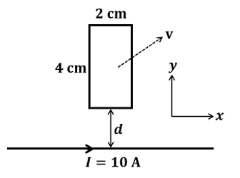
For a straight, infinitely long wire carrying current $$I$$, the magnetic field at a perpendicular distance $$r$$ from the wire is given by the Biot-Savart result
$$\vec B=\frac{\mu_0 I}{2\pi r}\,\hat{\phi},$$
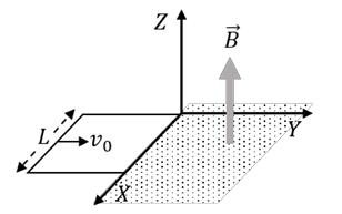
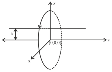
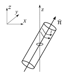
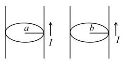
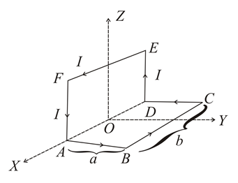
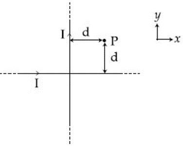
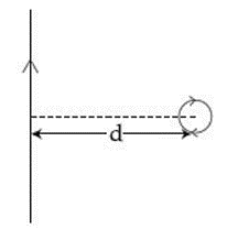
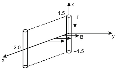
where $$\hat{\phi}$$ is the azimuthal (tangential) unit vector around the wire. In our situation the wire runs along the $$z$$-axis through the point $$(0,b,0)$$, so every field line lies in the $$xy$$-plane centred on that line.
Any current element $$I\,d\vec l$$ placed in a magnetic field experiences a differential force given by
$$d\vec F=I\;d\vec l\times\vec B.$$
The torque of this force about the $$z$$-axis is
$$d\tau_z=(\vec r\times d\vec F)_z=x\,dF_y-y\,dF_x,$$
with $$\vec r=(x,y,z)$$ measured from the origin.
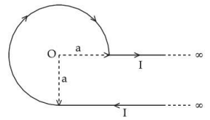
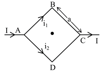
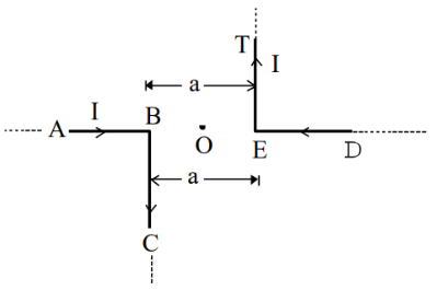
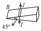
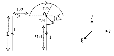
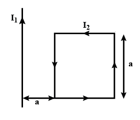
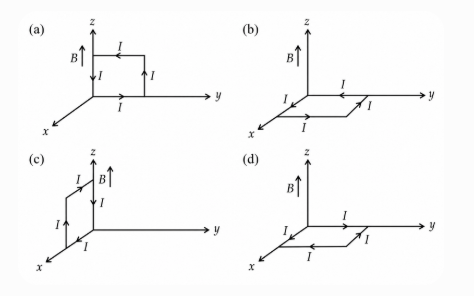
The square loop of side $$2a$$ lies in the $$xz$$-plane ($$y=0$$) and is centred at the origin, so its four straight sides are
1. $$AB: (-a,0,-a)\to(a,0,-a)\ \ (\text{along }+x)\\ 2. BC: (a,0,-a)\to(a,0,a)\ \ (\text{along }+z)\\ 3. CD: (a,0,a)\to(-a,0,a)\ \ (\text{along }-x)\\ 4. DA: (-a,0,a)\to(-a,0,-a)\ (\text{along }-z).$$
Because every point of the loop has coordinate $$y=0$$, the distance of a generic point $$(x,0,z)$$ from the wire is
$$r=\sqrt{x^{2}+b^{2}},$$
and the magnetic field there is obtained by writing the azimuthal unit vector explicitly. The vector from the wire to the field point is $$\vec r=x\,\hat i-b\,\hat j,$$ so
$$\hat{\phi}=\frac{\hat k\times\vec r}{|\vec r|}=\frac{b\,\hat i+x\,\hat j}{r}.$$
Substituting in the Biot-Savart expression gives the field on the loop:
$$\vec B(x)=\frac{\mu_0 I}{2\pi r}\;\hat{\phi}= \frac{\mu_0 I}{2\pi}\;\frac{b\,\hat i+x\,\hat j}{x^{2}+b^{2}}.$$
Now we treat each side in turn.
Sides AB and CD (segments parallel to the $$x$$-axis)
On these sides $$d\vec l=\pm dx\,\hat i$$, so
$$d\vec F=I\,d\vec l\times\vec B =I\,dx\,\hat i\times\frac{\mu_0 I}{2\pi}\frac{b\,\hat i+x\,\hat j}{x^{2}+b^{2}} =\frac{\mu_0 I^{2}}{2\pi}\frac{x\,dx}{x^{2}+b^{2}}\;\hat k.$$ Because the force is purely along $$\hat k$$, both $$F_x$$ and $$F_y$$ are zero and therefore $$d\tau_z=0$$ on these two sides. They contribute no torque about the $$z$$-axis.
Side BC (segment parallel to the $$z$$-axis at $$x=+a$$)
Here $$d\vec l=dz\,\hat k$$ and $$x=a$$ is constant, so
$$d\vec F_{BC}=I\,dz\,\hat k\times \frac{\mu_0 I}{2\pi}\frac{b\,\hat i+a\,\hat j}{a^{2}+b^{2}} =\frac{\mu_0 I^{2}}{2\pi(a^{2}+b^{2})}\,dz\, \bigl[b\,(\hat k\times\hat i)+a\,(\hat k\times\hat j)\bigr] =\frac{\mu_0 I^{2}}{2\pi(a^{2}+b^{2})}\,dz\,(b\,\hat j-a\,\hat i).$$
Its components are $$F_x=-\dfrac{\mu_0 I^{2}a}{2\pi(a^{2}+b^{2})}\,dz$$ and $$F_y=\dfrac{\mu_0 I^{2}b}{2\pi(a^{2}+b^{2})}\,dz$$. The position vector on this side is $$\vec r=(a,0,z)$$, so
$$d\tau_z^{(BC)}=x\,dF_y-y\,dF_x=a\,dF_y =\frac{\mu_0 I^{2}a b}{2\pi(a^{2}+b^{2})}\,dz.$$
Integrating $$z$$ from $$-a$$ to $$+a$$ we obtain
$$\tau_z^{(BC)}=\int_{-a}^{a}d\tau_z^{(BC)} =\frac{\mu_0 I^{2}a b}{2\pi(a^{2}+b^{2})}\,(2a) =\frac{\mu_0 I^{2}a^{2} b}{\pi(a^{2}+b^{2})}.$$
Side DA (segment parallel to the $$z$$-axis at $$x=-a$$)
On this side the current runs in the negative $$z$$-direction, so we write $$d\vec l=-dz\,\hat k$$ while $$x=-a$$. The magnetic field there is
$$\vec B(-a)=\frac{\mu_0 I}{2\pi}\frac{b\,\hat i- a\,\hat j}{a^{2}+b^{2}}.$$
Hence
$$d\vec F_{DA}=I\,(-dz\,\hat k)\times \frac{\mu_0 I}{2\pi}\frac{b\,\hat i- a\,\hat j}{a^{2}+b^{2}} =-\frac{\mu_0 I^{2}}{2\pi(a^{2}+b^{2})}\,dz\, \bigl[b\,(\hat k\times\hat i)-a\,(\hat k\times\hat j)\bigr] =-\frac{\mu_0 I^{2}}{2\pi(a^{2}+b^{2})}\,dz\,(b\,\hat j+a\,\hat i).$$
The components are $$F_x=-\dfrac{\mu_0 I^{2}a}{2\pi(a^{2}+b^{2})}\,dz$$, $$F_y=-\dfrac{\mu_0 I^{2}b}{2\pi(a^{2}+b^{2})}\,dz$$. With $$\vec r=(-a,0,z)$$ we have
$$d\tau_z^{(DA)}=x\,dF_y-y\,dF_x=(-a)(dF_y) =\frac{\mu_0 I^{2}a b}{2\pi(a^{2}+b^{2})}\,dz,$$
exactly the same integrand as for side BC. Integrating from $$z=+a$$ back to $$z=-a$$ (the physical direction of current) still produces
$$\tau_z^{(DA)}=\frac{\mu_0 I^{2}a^{2} b}{\pi(a^{2}+b^{2})}.$$
Total torque about the $$z$$-axis
The two horizontal sides give zero torque, while each vertical side contributes the same positive amount found above, so
$$\tau_z=\tau_z^{(BC)}+\tau_z^{(DA)} =\frac{\mu_0 I^{2}a^{2} b}{\pi(a^{2}+b^{2})} +\frac{\mu_0 I^{2}a^{2} b}{\pi(a^{2}+b^{2})} =\frac{2\mu_0 I^{2}a^{2} b}{\pi(a^{2}+b^{2})}.$$
Therefore the magnitude of the torque acting on the square loop about the $$z$$-axis is
$$\boxed{\displaystyle \tau=\frac{2\mu_0 I^{2}a^{2} b}{\pi\!\left(a^{2}+b^{2}\right)}}.$$
Hence, the correct answer is Option B.
A square loop of side $$2a$$, and carrying current $$I$$, is kept in $$XZ$$ plane with its centre at origin. A long wire carrying the same current $$I$$ is placed parallel to the $$z$$-axis and passing through the point $$(0, b, 0)$$, $$(b >> a)$$. The magnitude of the torque on the loop about $$z$$-axis is given by:
We have a square current-carrying loop of side $$2a$$ whose plane is the $$XZ$$-plane and whose centre is at the origin. Hence every point of the loop has coordinate $$y = 0$$. The loop carries current $$I$$. A very long straight conductor, also carrying the same current $$I$$, is parallel to the $$z$$-axis and passes through the fixed point $$(0,\, b,\, 0)$$ with $$b \gg a$$. Thus the straight wire is at a perpendicular distance $$b$$ from the centre of the square loop.
First we note the magnetic moment (also called magnetic dipole moment) of a current loop. For any closed loop the magnitude is given by the formula
$$m \;=\; I \, A,$$
where $$A$$ is the area enclosed by the loop and its direction is perpendicular to the plane of the loop according to the right-hand rule. Here the area of the square is
$$A \;=\; (2a)\times(2a) \;=\; 4a^{2}.$$
Hence the magnitude of the magnetic moment of the square loop is
$$m \;=\; I \,(4a^{2}) \;=\; 4 I a^{2}.$$
The loop lies in the $$XZ$$-plane, so its area vector (and therefore its magnetic-moment vector) points along the $$\pm y$$-axis. We shall simply denote its magnitude by $$m$$ and keep in mind that its direction is along $$\hat y$$ or $$-\hat y$$ depending on the sense of current; that sign will automatically be taken care of by the cross product.
Next we need the magnetic field produced by the long straight wire at a generic point of the loop. For an infinitely long wire the magnitude of the magnetic field at a perpendicular distance $$r$$ is given by the standard Biot-Savart result
$$B \;=\;\frac{\mu_{0} I}{2\pi r}.$$
The distance of the centre of the loop from the wire is exactly $$b$$, so the field at the centre due to the wire is
$$B_{0} \;=\;\frac{\mu_{0} I}{2\pi b}.$$
Because we are told that $$b \gg a$$, every point of the square loop is very nearly at the same distance $$b$$ from the wire; the fractional variation in distance is only of order $$a/b$$. Therefore, to an excellent approximation, we can treat the magnetic field over the whole loop as uniform and equal to $$B_{0}$$ in magnitude and direction. This simplification allows us to use the simple dipole-torque formula instead of integrating the force on each element.
The torque $$\vec\tau$$ acting on a current loop of magnetic moment $$\vec m$$ placed in a (uniform) magnetic field $$\vec B$$ is given by the vector relation
$$\vec\tau \;=\; \vec m \times \vec B.$$
The magnitude of the torque is therefore
$$\tau \;=\; m B \sin\theta,$$
where $$\theta$$ is the angle between $$\vec m$$ and $$\vec B$$. In our geometry the magnetic field of the straight wire is tangential to a circle centred on the wire; at the origin (centre of the square) that direction is along the $$+x$$-axis. Thus $$\vec B$$ is along $$\hat x$$ while $$\vec m$$ is along $$\pm\hat y$$, so the angle between them is exactly $$90^\circ$$ and $$\sin\theta = 1$$.
Putting everything together, the magnitude of the torque is
$$\tau \;=\; m B_{0} \;=\; \bigl(4 I a^{2}\bigr) \left(\frac{\mu_{0} I}{2\pi b}\right).$$
Multiplying the factors gives
$$\tau \;=\; \frac{4\,\mu_{0}\,I^{2}\,a^{2}}{2\pi b} \;=\; \frac{2\,\mu_{0}\,I^{2}\,a^{2}}{\pi b}.$$
This matches option C in the list provided.
Hence, the correct answer is Option 3.
A galvanometer coil has 500 turns and each turn has an average area of $$3 \times 10^{-4}$$ m$$^2$$. If a torque of 1.5 Nm is required to keep this coil parallel to a magnetic field when a current of 0.5A is flowing through it, the strength of the field (in T) is __________.
We recall the torque formula for a current-carrying coil placed in a uniform magnetic field. The magnitude of the torque is given by
$$\tau = N I A B \sin\theta,$$
where $$N$$ is the number of turns, $$I$$ is the current, $$A$$ is the area of each turn, $$B$$ is the magnetic-field strength, and $$\theta$$ is the angle between the magnetic-field direction and the normal to the plane of the coil.
Now the coil is stated to be parallel to the magnetic field. This makes the normal to the coil perpendicular to the field, giving $$\theta = 90^\circ$$ and hence $$\sin\theta = 1$$. Therefore the expression for torque simplifies to
$$\tau = N I A B.$$
We substitute the given numerical values. We have
$$N = 500, \qquad I = 0.5\ \text{A}, \qquad A = 3 \times 10^{-4}\ \text{m}^2, \qquad \tau = 1.5\ \text{N\,m}.$$
Putting these into the simplified torque formula gives
$$1.5 = 500 \times 0.5 \times \left(3 \times 10^{-4}\right) \times B.$$
First evaluate the product in the denominator step by step:
$$500 \times 0.5 = 250,$$
$$250 \times 3 = 750,$$
$$750 \times 10^{-4} = 7.5 \times 10^{-2} = 0.075.$$
So we have
$$1.5 = 0.075 \, B.$$
Solving for $$B$$, we divide both sides by 0.075:
$$B = \frac{1.5}{0.075} = 20.$$
Thus the required magnetic-field strength is
$$B = 20\ \text{T}.$$
So, the answer is $$20\ \text{T}$$.
A loop ABCDEFA of straight edges has six corner points A(0, 0, 0), B(5, 0, 0), C(5, 5, 0), D(0, 5, 0), E(0, 5, 5) and F(0, 0, 5). The magnetic field in this region is $$\vec{B} = (3\hat{i} + 4\hat{k})$$ T. The quantity of flux through the loop ABCDEFA (in Wb) is
We are asked to find the magnetic flux through the wire loop that follows the edges A → B → C → D → E → F → A, where the corner coordinates are
$$$A(0,0,0),\, B(5,0,0),\, C(5,5,0),\, D(0,5,0)$$$, $$E(0,5,5),\, F(0,0,5).$$
The magnetic field in the region is uniform and given by
$$\vec B = 3\hat i + 4\hat k\;\text{ T}.$$
The loop is not planar, so instead of splitting the surface into several rectangles, it is quicker to use a vector formula that gives the net area vector directly from the boundary curve. For any closed contour $$\mathcal C$$, an oriented surface bounded by that contour has area vector
$$\vec A \;=\;\frac12\oint_{\mathcal C}\vec r\times d\vec r,$$
where $$\vec r$$ is the position vector of a point on the contour and $$d\vec r$$ is the differential displacement along the contour. This follows from Stokes’ theorem and is valid no matter how the surface is bent; the result depends only on the boundary.
We therefore evaluate the line integral $$\displaystyle\oint\vec r\times d\vec r$$ one edge at a time, always moving in the given order A → B → C → D → E → F → A.
Edge AB: $$$\vec r=\langle x,0,0\rangle,\;0\le x\le5,\;d\vec r=\langle dx,0,0\rangle.$$$ So $$\vec r\times d\vec r=\vec0,$$ and the integral along AB is $$\vec0.$$
Edge BC: $$$\vec r=\langle5,y,0\rangle,\;0\le y\le5,\;d\vec r=\langle0,dy,0\rangle.$$$ Then $$$\vec r\times d\vec r=\begin{vmatrix}\hat i&\hat j&\hat k\\5&y&0\\0&dy&0\end{vmatrix}=5\,dy\,\hat k.$$$ Integrating, $$\int_{0}^{5}5\,dy\,\hat k=25\hat k.$$
Edge CD: $$$\vec r=\langle x,5,0\rangle,\;5\ge x\ge0,\;d\vec r=\langle dx,0,0\rangle.$$$ Here $$$\vec r\times d\vec r=\begin{vmatrix}\hat i&\hat j&\hat k\\x&5&0\\dx&0&0\end{vmatrix}=-5\,dx\,\hat k.$$$ Integrating from 5 down to 0, $$\int_{5}^{0}(-5)\,dx\,\hat k=25\hat k.$$
Edge DE: $$$\vec r=\langle0,5,z\rangle,\;0\le z\le5,\;d\vec r=\langle0,0,dz\rangle.$$$ Thus $$$\vec r\times d\vec r=\begin{vmatrix}\hat i&\hat j&\hat k\\0&5&z\\0&0&dz\end{vmatrix}=5\,dz\,\hat i.$$$ Integrating, $$\int_{0}^{5}5\,dz\,\hat i=25\hat i.$$
Edge EF: $$$\vec r=\langle0,y,5\rangle,\;5\ge y\ge0,\;d\vec r=\langle0,dy,0\rangle.$$$ Then $$$\vec r\times d\vec r=\begin{vmatrix}\hat i&\hat j&\hat k\\0&y&5\\0&dy&0\end{vmatrix}=-5\,dy\,\hat i.$$$ Integrating from 5 down to 0, $$\int_{5}^{0}(-5)\,dy\,\hat i=25\hat i.$$
Edge FA: $$$\vec r=\langle0,0,z\rangle,\;5\ge z\ge0,\;d\vec r=\langle0,0,dz\rangle.$$$ The cross‐product is zero, so the contribution is $$\vec0.$$
Adding all six contributions we get
$$$\oint\vec r\times d\vec r=(25+25)\hat i+(25+25)\hat k= \langle50,\,0,\,50\rangle.$$$
Dividing by 2, the area vector bounded by the loop is
$$$\vec A=\frac12\langle50,\,0,\,50\rangle=\langle25,\,0,\,25\rangle\text{ m}^2.$$$
Magnetic flux is defined as
$$\Phi=\vec B\cdot\vec A.$$
Substituting $$\vec B=\langle3,\,0,\,4\rangle\text{ T}$$ and $$\vec A=\langle25,\,0,\,25\rangle\text{ m}^2,$$ we have
$$$\Phi=(3)(25)+(0)(0)+(4)(25)=75+100=175\;\text{Wb}.$$$
So, the answer is $$175$$.
A moving coil galvanometer allows a full scale current of $$10^{-4}$$ A. A series resistance of $$2 \times 10^4$$ Ω is required to convert the galvanometer into a voltmeter of range 0 - 5 V. Therefore, the value of shunt resistance required to convert the above galvanometer into an ammeter of range 0 - 10 mA is:
We are told that the galvanometer gives full-scale deflection when a current of $$I_g = 10^{-4}\ {\rm A}$$ flows through it. Its own resistance is not given directly; we must first find it.
When the galvanometer is converted into a voltmeter of range $$0 - 5\ {\rm V}$$, a series resistance $$R_s = 2 \times 10^4\ \Omega$$ is connected.
For a voltmeter, the full-scale voltage is related to the full-scale current by the well-known relation
$$V = I_g\,(G + R_s),$$
where $$G$$ is the resistance of the galvanometer itself.
Substituting the known values, we have
$$5 = 10^{-4}\,(G + 2 \times 10^4).$$
Dividing both sides by $$10^{-4}$$ gives
$$5 \div 10^{-4} = G + 2 \times 10^4.$$
Since $$5 \div 10^{-4} = 5 \times 10^{4} = 5.0 \times 10^{4} = 50000,$$ we write
$$50000 = G + 20000.$$
So,
$$G = 50000 - 20000 = 30000\ \Omega = 3 \times 10^{4}\ \Omega.$$
Now we have the galvanometer resistance $$G = 3 \times 10^{4}\ \Omega$$ and its full-scale current $$I_g = 10^{-4}\ {\rm A}.$$
Next, we must convert this galvanometer into an ammeter of range $$0 - 10\ {\rm mA} = 0.01\ {\rm A}.$$ To do this, we place a shunt resistance $$S$$ in parallel with the galvanometer.
The standard formula for the required shunt is
$$S = \frac{I_g\,G}{I - I_g},$$
where $$I$$ is the desired full-scale ammeter current.
Substituting $$I_g = 10^{-4}\ {\rm A},\; G = 3 \times 10^{4}\ \Omega,\; I = 0.01\ {\rm A},$$ we get
$$S = \frac{(10^{-4})(3 \times 10^{4})}{0.01 - 10^{-4}}.$$
Evaluating the numerator,
$$(10^{-4})(3 \times 10^{4}) = 3.$$
The denominator is
$$0.01 - 0.0001 = 0.0099.$$
Hence,
$$S = \frac{3}{0.0099}\ \Omega.$$
Computing this quotient gives
$$S \approx 303\ \Omega.$$ Since the nearest tabulated option is $$300\ \Omega,$$ we take that as the required shunt.
Hence, the correct answer is Option C.
A moving coil galvanometer, having a resistance G, produces full scale deflection when a current I$$_G$$ flows through it. This galvanometer can be converted into (i) an ammeter of range 0 to I$$_0$$ (I$$_0$$ > I$$_g$$) by connecting a shunt resistance R$$_A$$ to it and (ii) into a voltmeter of range 0 to V (V = GI$$_0$$) by connecting a series resistance R$$_V$$ to it. Then,
We begin with a moving-coil galvanometer of resistance $$G$$. Whenever a current $$I_G$$ passes through it, the pointer shows full-scale deflection.
First we convert this galvanometer into an ammeter of range $$0$$ to $$I_0$$, where $$I_0 > I_G$$. For that purpose we connect a shunt resistance $$R_A$$ in parallel with the galvanometer.
In the parallel arrangement the potential difference across the galvanometer equals the potential difference across the shunt. Thus
$$I_G\,G \;=\;(I_0 - I_G)\,R_A\;.$$
Now we solve for $$R_A$$ algebraically. Dividing both sides by $$(I_0 - I_G)$$ and then by $$1$$ (to keep the steps explicit) we get
$$R_A \;=\;\frac{I_G\,G}{I_0 - I_G}\;.$$
Next, we convert the same galvanometer into a voltmeter capable of measuring from $$0$$ to a voltage $$V$$. The question already tells us that this voltage is related to the ammeter range by $$V = G I_0$$. To obtain such a voltmeter we place a series resistance $$R_V$$ with the galvanometer.
The current through the voltmeter at full scale must still be $$I_G$$ (any larger current would damage the movement). Hence Ohm’s law for the whole series combination gives
$$V \;=\; I_G\,(G + R_V)\;.$$
We substitute the given value $$V = G I_0$$ and obtain
$$G I_0 \;=\; I_G\,(G + R_V)\;.$$
Now we solve explicitly for $$R_V$$. First divide both sides by $$I_G$$:
$$\frac{G I_0}{I_G} \;=\; G + R_V\;.$$
Next subtract $$G$$ from both sides:
$$R_V \;=\; \frac{G I_0}{I_G} - G\;.$$
Taking $$G$$ common in the right‐hand expression gives
$$R_V \;=\; G\!\left(\frac{I_0}{I_G} - 1\right)\;=\; G\,\frac{I_0 - I_G}{I_G}\;.$$
We now have explicit expressions for both resistances:
$$R_A = \frac{I_G\,G}{\,I_0 - I_G\,}, \qquad R_V = G\,\frac{I_0 - I_G}{I_G}\;.$$
To see what products and ratios these expressions give, we first multiply the two:
$$R_A\,R_V \;=\; \frac{I_G\,G}{I_0 - I_G} \times G\,\frac{I_0 - I_G}{I_G}\;.$$
The factors $$I_G$$ and $$I_G$$ cancel, as do the factors $$(I_0 - I_G)$$. We are left with
$$R_A\,R_V \;=\; G^2\;.$$
Next, we form the ratio $$\dfrac{R_A}{R_V}$$. Using the same explicit expressions we obtain
$$\frac{R_A}{R_V} \;=\; \frac{\displaystyle\frac{I_G\,G}{I_0 - I_G}} {\displaystyle G\,\frac{I_0 - I_G}{I_G}} \;=\; \frac{I_G\,G}{I_0 - I_G}\times\frac{I_G}{G\,(I_0 - I_G)}\;.$$
The factor $$G$$ cancels from numerator and denominator, giving
$$\frac{R_A}{R_V} \;=\; \frac{I_G^2}{(I_0 - I_G)^2}\;=\;\left(\frac{I_G}{I_0 - I_G}\right)^{\!2}\;.$$
Putting it all together, we have derived
$$R_A\,R_V = G^2,\qquad \frac{R_A}{R_V} = \left(\frac{I_G}{I_0 - I_G}\right)^2\;.$$
These match exactly the relationships stated in Option D.
Hence, the correct answer is Option D.
A circular coil having N turns and radius r carries a current I. It is held in the XZ plane in a magnetic field $$B\hat{i}$$. The torque on the coil due to the magnetic field is:
We recall the general result for a current-carrying coil in a uniform magnetic field. A planar coil with $$N$$ turns, carrying current $$I$$, and having vector area $$\vec A$$ possesses a magnetic dipole moment $$\vec\mu$$ defined by the formula
$$\vec\mu = N\,I\,\vec A.$$
Here the vector $$\vec A$$ has magnitude equal to the geometrical area of the coil and its direction is perpendicular to the plane of the coil, obtained from the right-hand rule (curl the fingers in the sense of current, the thumb gives the direction of $$\vec A$$).
The torque $$\vec\tau$$ acting on a magnetic dipole in a uniform magnetic field $$\vec B$$ is given by the vector formula
$$\vec\tau = \vec\mu \times \vec B.$$
From this cross-product, the magnitude of the torque is
$$\tau = \mu\,B\,\sin\theta,$$
where $$\theta$$ is the angle between the magnetic moment $$\vec\mu$$ (or equivalently the area vector $$\vec A$$) and the magnetic field $$\vec B$$.
Now, for the circular coil described in the question:
• It has $$N$$ turns.
• Its radius is $$r$$, so its geometrical area (for one turn) is
$$A = \pi r^{2}.$$
Because the coil lies in the $$XZ$$-plane, its area vector (and hence $$\vec\mu$$) is directed along the $$\pm \hat{j}$$ (the $$Y$$) axis. The magnetic field is given as $$\vec B = B\,\hat{i},$$ i.e. along the $$X$$ axis. Therefore the angle $$\theta$$ between $$\vec\mu$$ (along $$\hat{j}$$) and $$\vec B$$ (along $$\hat{i}$$) is
$$\theta = 90^\circ,$$
for which $$\sin\theta = \sin 90^\circ = 1.$$
First, write the magnitude of the magnetic dipole moment:
$$\mu = N\,I\,A = N\,I\,(\pi r^{2}).$$
Substituting this value and $$\sin\theta = 1$$ into the torque formula, we have
$$\tau = \mu\,B\,\sin\theta = \bigl(N\,I\,\pi r^{2}\bigr)\,B\,(1).$$
Simplifying the factors, the magnitude of the torque becomes
$$\tau = B\,\pi r^{2}\,I\,N.$$
This matches exactly the expression given in Option A.
Hence, the correct answer is Option A.
A particle having the same charge as of electron moves in a circular path of radius 0.5 cm under the influence of a magnetic field of 0.5 T. If an electric field of 100 V/m makes it to move in a straight path, then the mass of the particle is (Given charge of electron $$= 1.6 \times 10^{-19}$$ C)
We are told that the particle carries the same charge as an electron, so its charge is
$$q = 1.6 \times 10^{-19}\ \text{C}.$$
Under only the magnetic field, the particle executes uniform circular motion of radius
$$r = 0.5\ \text{cm} = 0.5 \times 10^{-2}\ \text{m} = 5 \times 10^{-3}\ \text{m}.$$
The magnetic field magnitude is
$$B = 0.5\ \text{T}.$$
For a charged particle moving perpendicular to a uniform magnetic field, the magnetic force supplies the centripetal force. We first state this relationship:
Magnetic force: $$F_B = q v B.$$ Centripetal force: $$F_C = \dfrac{m v^{2}}{r}.$$
Because the motion is circular under the magnetic field alone, these two forces are equal:
$$q v B = \dfrac{m v^{2}}{r}.$$
We can cancel one factor of the speed $$v$$ from both sides to find an expression for $$v$$:
$$q B = \dfrac{m v}{r}\quad \Longrightarrow\quad v = \dfrac{q B r}{m}.$$
Next, an electric field of magnitude
$$E = 100\ \text{V m}^{-1}$$
is switched on simultaneously with the magnetic field. The problem states that, under the simultaneous action of $$ \mathbf{E} $$ and $$ \mathbf{B} $$, the particle now moves in a straight line. A straight-line trajectory in crossed, perpendicular electric and magnetic fields implies that the net force is zero. The electric force and magnetic force must therefore cancel:
Electric force: $$F_E = q E.$$ Magnetic force (already written): $$F_B = q v B.$$
For cancellation, we must have
$$q E = q v B.$$
Because $$q \neq 0$$, we divide both sides by $$q$$ to obtain the standard crossed-fields condition:
$$E = v B \quad\Longrightarrow\quad v = \dfrac{E}{B}.$$
We now have two independent expressions for the speed $$v$$:
$$v = \dfrac{q B r}{m}\qquad\text{and}\qquad v = \dfrac{E}{B}.$$
Since both describe the same speed, we equate them:
$$\dfrac{q B r}{m} = \dfrac{E}{B}.$$
Solving this equation for the mass $$m$$, we first cross-multiply:
$$q B r \, B = m E.$$
This simplifies to
$$m = \dfrac{q B^{2} r}{E}.$$
Now we substitute the numerical values, keeping all factors explicit:
$$m = \dfrac{(1.6 \times 10^{-19}\ \text{C})\,(0.5\ \text{T})^{2}\,(5 \times 10^{-3}\ \text{m})}{100\ \text{V m}^{-1}}.$$
First calculate the square of the magnetic field:
$$(0.5\ \text{T})^{2} = 0.25\ \text{T}^{2}.$$
Multiply $$q$$ and $$B^{2}$$:
$$1.6 \times 10^{-19} \times 0.25 = 0.4 \times 10^{-19} = 4.0 \times 10^{-20}.$$
Now include the radius $$r$$:
$$4.0 \times 10^{-20} \times 5 \times 10^{-3} = 20.0 \times 10^{-23} = 2.0 \times 10^{-22}.$$
Finally, divide by the electric field magnitude $$E = 100 = 1.0 \times 10^{2}$$:
$$m = \dfrac{2.0 \times 10^{-22}}{1.0 \times 10^{2}} = 2.0 \times 10^{-24}\ \text{kg}.$$
This value exactly matches option C.
Hence, the correct answer is Option C.
A proton and an $$\alpha$$-particle (with their masses in the ratio of 1 : 4 and charges in the ratio of 1 : 2) are accelerated from rest through a potential difference V. If a uniform magnetic field (B) is set up perpendicular to their velocities, the ratio of the radii $$r_p : r_{\alpha}$$ of the circular paths described by them will be:
We begin by recalling the motion of a charged particle in a uniform magnetic field. When a particle of mass $$m$$ and charge $$q$$ enters a field $$B$$ with velocity $$v$$ perpendicular to the field, it moves in a circle of radius
$$r=\dfrac{mv}{qB}\,.$$
Next, because each particle starts from rest and is accelerated through the same potential difference $$V$$, the work-energy theorem gives the kinetic energy gained:
$$qV=\dfrac12\,mv^{2}\;.$$
Solving this energy equation for the speed, we obtain
$$v=\sqrt{\dfrac{2qV}{m}}\;.$$
Substituting this value of $$v$$ into the formula for the radius, we arrive at
$$r=\dfrac{m}{qB}\,\sqrt{\dfrac{2qV}{m}} =\dfrac{1}{B}\,\sqrt{\dfrac{2mV}{q}}\;.$$
Thus, for any particle accelerated through the same potential difference $$V$$ and entering the same magnetic field $$B$$, the radius is proportional to $$\sqrt{\dfrac{m}{q}}$$.
Let us now evaluate this expression for the two given particles.
For the proton: its mass is $$m_{p}=m$$ and its charge is $$q_{p}=e$$. Therefore
$$r_{p}=\dfrac1B\,\sqrt{\dfrac{2mV}{e}}\;.$$
For the $$\alpha$$-particle: its mass is $$m_{\alpha}=4m$$ and its charge is $$q_{\alpha}=2e$$. Hence
$$r_{\alpha}=\dfrac1B\,\sqrt{\dfrac{2(4m)V}{2e}} =\dfrac1B\,\sqrt{\dfrac{8mV}{2e}} =\dfrac1B\,\sqrt{\dfrac{4mV}{e}} =\dfrac1B\;\;2\,\sqrt{\dfrac{mV}{e}}\;.$$
We now write the ratio of the two radii:
$$\dfrac{r_{p}}{r_{\alpha}} =\dfrac{\displaystyle \dfrac1B\,\sqrt{\dfrac{2mV}{e}}} {\displaystyle \dfrac1B\,2\,\sqrt{\dfrac{mV}{e}}} =\dfrac{\sqrt{2}}{2} =\dfrac1{\sqrt{2}}\;.$$
This gives
$$r_{p}:r_{\alpha}=1:\sqrt{2}\;.$$
Hence, the correct answer is Option B.
An electron, moving along the x-axis with an initial energy of 100 eV, enters a region of magnetic field $$\vec{B} = (1.5 \times 10^{-3}$$ T)$$\hat{k}$$ at S (see figure). The field extends between x = 0 and x = 2 cm. The electron is detected at the point Q on a screen placed 8 cm away from the point S. The distance d between P and Q (on the screen) is:
(electron’s charge $$1.6 ×10^{−19} C$$, mass of electron $$=9.1×10^{−31} kg$$)
In an experiment, electrons are accelerated, from rest, by applying a voltage of 500 V. Calculate the radius of the path if a magnetic field 100 mT is then applied. [Charge of the electron $$= 1.6 \times 10^{-19}$$ C; Mass of the electron $$= 9.1 \times 10^{-31}$$ kg]
Two wires A & B are carrying currents I$$_1$$ and I$$_2$$ as shown in the figure. The separation between them is d. A third wire C carrying a current I is to be kept parallel to them at a distance x from A such that the net force acting on it is zero. The possible values of x are:
A proton, an electron, and a Helium nucleus, have the same energy. They are in circular orbits in a plane due to magnetic field perpendicular to the plane. Let $$r_p$$, $$r_e$$ and $$r_{He}$$ be their respective radii, then,
We consider a uniform magnetic field that is perpendicular to the plane of motion of the charged particle. For a charged particle of charge $$q$$ and mass $$m$$ moving with speed $$v$$ in a circle of radius $$r$$, the magnetic Lorentz force provides the required centripetal force. The relation is
$$q\,v\,B = \dfrac{m v^{2}}{r}$$First we isolate the radius $$r$$. Cancelling one factor of $$v$$ from both sides, we obtain
$$q B = \dfrac{m v}{r} \quad \Longrightarrow \quad r = \dfrac{m v}{q B}$$The question tells us that the proton, the electron, and the Helium nucleus all possess the same kinetic energy, which we denote by $$E$$. The kinetic energy of a particle is given by
$$E = \dfrac{1}{2} m v^{2}$$Solving this expression for the speed $$v$$, we have
$$v = \sqrt{\dfrac{2E}{m}}$$We now substitute this expression for $$v$$ into the formula for the radius:
$$r = \dfrac{m}{q B} \,\sqrt{\dfrac{2E}{m}} = \dfrac{\sqrt{2 E}\, \sqrt{m}}{q B}$$The factors $$\sqrt{2E}$$ and $$B$$ are common to all three particles because the energy and the magnetic field are the same for each. Hence, for comparison of radii, we may write the proportionality
$$r \;\propto\; \dfrac{\sqrt{m}}{q}$$Therefore, the ordering of the radii depends solely on the ratio $$\sqrt{m}/q$$ for the proton, the electron, and the Helium nucleus. We list their masses and charges (magnitude of charge only, because radius is a positive quantity):
- Electron: $$m = m_e,\; q = e$$
- Proton: $$m = m_p,\; q = e$$
- Helium nucleus (alpha particle): $$m = 4 m_p,\; q = 2e$$
Now we compute the proportional factors:
$$ \begin{aligned} r_e &\propto \dfrac{\sqrt{m_e}}{e},\\[4pt] r_p &\propto \dfrac{\sqrt{m_p}}{e},\\[4pt] r_{He} &\propto \dfrac{\sqrt{4 m_p}}{2e} = \dfrac{2\sqrt{m_p}}{2e} = \dfrac{\sqrt{m_p}}{e}. \end{aligned} $$We immediately observe that
$$r_{He} \propto \dfrac{\sqrt{m_p}}{e} = r_p.$$Thus $$r_{He} = r_p.$$ To compare with the electron, note that the electron’s mass is enormously smaller than the proton’s mass, i.e.
$$m_e \ll m_p \quad\Longrightarrow\quad \sqrt{m_e} \ll \sqrt{m_p}.$$Consequently
$$r_e \propto \dfrac{\sqrt{m_e}}{e} \ll \dfrac{\sqrt{m_p}}{e} \propto r_p = r_{He}.$$Collecting these results, we obtain the order
$$r_e \lt r_p = r_{He}.$$This ordering corresponds to Option B.
Hence, the correct answer is Option B.
As shown in the figure, two infinitely long, identical wires are bent by 90° and placed in such a way that the segments LP and QM are along the x-axis, while segments PS and QN are parallel to the y-axis. If $$OP = OQ = 4$$ cm, and the magnitude of the magnetic field at O is $$10^{-4}$$ T, and the two wires carry equal currents (see figure), the magnitude of the current in each wire and the direction of the magnetic field at O will be $$\left(\mu_0 = 4\pi \times 10^{-7} NA^{-2}\right)$$:
Find the magnetic field at point P due to a straight line segment AB of length 6 cm carrying a current of 5 A. (See figure) ($$\mu_0 = 4\pi \times 10^{-7}$$ NA$$^{-2}$$)
One of the two identical conducting wires of length $$L$$ is bent in the form of a circular loop and the other one into a circular coil of $$N$$ identical turns. If the same current is passed in both, the ratio of the magnetic field at the centre of the loop $$(B_L)$$ to that at the centre of the coil $$(B_C)$$, i.e. $$\frac{B_L}{B_C}$$ will be:
Let the current flowing through both wires be $$I$$ and let the total length of each wire be $$L$$. Both wires are identical, so they have the same length.
First we take the wire that is bent into a single circular loop. If the radius of this loop is $$R_1$$, then its circumference must equal the length of the wire. Therefore, using the basic relation “circumference = $$2\pi\times\text{radius}$$”, we have
$$2\pi R_1 = L \;\;\Longrightarrow\;\; R_1 = \frac{L}{2\pi}.$$
The magnetic field at the centre of a single circular loop carrying current $$I$$ is given by the standard formula
$$B = \frac{\mu_0 I}{2R}.$$
Substituting $$R = R_1$$, we obtain the field at the centre of this loop:
$$B_L = \frac{\mu_0 I}{2R_1} = \frac{\mu_0 I}{2\left(\dfrac{L}{2\pi}\right)} = \frac{\mu_0 I}{2}\cdot\frac{2\pi}{L} = \frac{\mu_0 I\pi}{L}.$$
Now consider the second wire that is wound into a circular coil of $$N$$ identical turns. Let the radius of each turn be $$R_2$$. Because there are $$N$$ turns, the total length consumed is $$N$$ times the circumference of one turn. Hence
$$N\,(2\pi R_2) = L \;\;\Longrightarrow\;\; R_2 = \frac{L}{2\pi N}.$$
The magnetic field at the centre of a circular coil having $$N$$ turns is $$N$$ times the field produced by one turn (all turns are coaxial and their fields add). Therefore, using the same single-turn formula but multiplied by $$N$$, we have
$$B_C = N\left(\frac{\mu_0 I}{2R_2}\right) = \frac{\mu_0 N I}{2R_2}.$$
Substituting $$R_2 = \dfrac{L}{2\pi N}$$ into the above expression gives
$$B_C = \frac{\mu_0 N I}{2\left(\dfrac{L}{2\pi N}\right)} = \frac{\mu_0 N I}{2}\cdot\frac{2\pi N}{L} = \frac{\mu_0 I\pi N^2}{L}.$$
We now form the required ratio $$\dfrac{B_L}{B_C}$$:
$$\frac{B_L}{B_C} = \frac{\dfrac{\mu_0 I\pi}{L}} {\dfrac{\mu_0 I\pi N^2}{L}} = \frac{\mu_0 I\pi}{L}\cdot\frac{L}{\mu_0 I\pi N^2} = \frac{1}{N^2}.$$
Hence, the correct answer is Option A.
The region between $$y = 0$$ and $$y = d$$ contains a magnetic field $$\vec{B} = B\hat{z}$$. A particle of mass m and charge q enters the region with a velocity $$\vec{v} = v\hat{i}$$. If $$d = \frac{mv}{2qB}$$, the acceleration of the charged particle at the point of its emergence at the other side is:
We begin with the Lorentz force law, which gives the magnetic force on a moving charge:
$$\vec F = q(\vec v \times \vec B).$$
Because the magnetic force is always perpendicular to the instantaneous velocity, the particle moves in a circular path of constant speed. The magnitude of the centripetal force equals the magnetic force, so
$$\frac{mv^{2}}{r}=qvB \quad\Longrightarrow\quad r=\frac{mv}{qB}.$$
The problem states that the strip of field extends from $$y=0$$ to $$y=d$$ with
$$d=\frac{mv}{2qB}=\frac{r}{2}.$$
Thus the particle travels only the lower half of the circle’s radius in the $$+y$$-direction while it is inside the field.
To follow the motion geometrically, let us place the centre of the circle at the point $$C(0,r)$$. The particle enters the field at the point $$P_{0}(0,0)$$ with velocity $$\vec v=v\hat i$$. Relative to the centre, the initial radius vector is $$\vec{CP}_{0}= -r\hat j$$, i.e. straight down. We measure an angular coordinate $$\theta$$ from this downward radius, increasing anticlockwise (toward $$+y$$).
Relative to the centre, the position vector is therefore
$$\vec r(\theta)=r\bigl(\sin\theta\,\hat i-\cos\theta\,\hat j\bigr).$$
Differentiating with respect to time gives the velocity direction:
$$\vec v(\theta)=\frac{d\vec r}{d\theta}\frac{d\theta}{dt} =r\dot\theta\bigl(\cos\theta\,\hat i+\sin\theta\,\hat j\bigr) =v\bigl(\cos\theta\,\hat i+\sin\theta\,\hat j\bigr),$$
because $$r\dot\theta=v$$ (the speed is unchanged).
The particle leaves the field when its $$y$$-coordinate equals $$d=r/2$$. The absolute $$y$$-coordinate is
$$y = r - r\cos\theta = r(1-\cos\theta).$$
Setting this equal to $$r/2$$ gives
$$r(1-\cos\theta)=\frac{r}{2}\;\;\Longrightarrow\;\;1-\cos\theta=\frac12 \;\;\Longrightarrow\;\;\cos\theta=\frac12 \;\;\Longrightarrow\;\;\theta=\frac{\pi}{3}\;(60^\circ).$$
Substituting $$\theta=\pi/3$$ into the velocity direction obtains
$$\vec v_{\text{exit}} =v\!\left(\frac12\,\hat i+\frac{\sqrt3}{2}\,\hat j\right).$$
Now we calculate the acceleration at the instant of exit. Using $$\vec a=\dfrac{q}{m}(\vec v\times\vec B)$$ with $$\vec B=B\hat k$$,
$$\vec v_{\text{exit}}\times\vec B =v\!\left(\frac12\,\hat i+\frac{\sqrt3}{2}\,\hat j\right)\!\times B\hat k =vB\!\left[ \frac12(\hat i\times\hat k)+\frac{\sqrt3}{2}(\hat j\times\hat k) \right].$$
Using the right-hand rule $$\hat i\times\hat k=-\hat j$$ and $$\hat j\times\hat k=\hat i$$, we get
$$\vec v_{\text{exit}}\times\vec B =vB\!\left[ \frac12(-\hat j)+\frac{\sqrt3}{2}\hat i \right] =vB\!\left( \frac{\sqrt3}{2}\,\hat i-\frac12\,\hat j \right).$$
Therefore
$$\boxed{\; \displaystyle \vec a_{\text{exit}} =\frac{qvB}{m}\left( \frac{\sqrt3}{2}\,\hat i-\frac12\,\hat j \right) \;} .$$
This vector is not identical to any of the three vectors listed in Options A, B and C, so none of those options is correct.
Hence, the correct answer is Option 4.
A moving coil galvanometer has a coil with 175 turns and area 1 cm$$^2$$. It uses a torsion band of torsion constant $$10^{-6}$$ N m/rad. The coil is placed in a magnetic field B parallel to its plane. The coil deflects by 1° for a current of 1 mA. The value of B (in tesla) is approximately:
The coil of the moving-coil galvanometer reaches equilibrium when the magnetic torque trying to turn the coil is exactly balanced by the restoring (torsional) torque of the suspension.
First, we state the two torques.
Magnetic torque on a current-carrying coil is given by the formula $$\tau_{\text{mag}} = n\,I\,A\,B\,\sin\phi,$$ where $$n$$ is the number of turns, $$I$$ is the current, $$A$$ is the area of each turn, $$B$$ is the magnetic-field magnitude, and $$\phi$$ is the angle between the normal to the coil and the magnetic field.
The problem tells us that the magnetic field is parallel to the plane of the coil. Hence the normal to the coil is perpendicular to the field, so $$\phi = 90^\circ$$ and $$\sin\phi = \sin 90^\circ = 1.$$ Therefore, the magnetic torque reduces to $$\tau_{\text{mag}} = n\,I\,A\,B.$$
The restoring torque supplied by the torsion band obeys Hooke’s law for angular twist: $$\tau_{\text{rest}} = C\,\theta,$$ where $$C$$ is the torsion (restoring) constant and $$\theta$$ is the angular deflection in radians.
At equilibrium we have $$\tau_{\text{mag}} = \tau_{\text{rest}}.$$ So, $$n\,I\,A\,B = C\,\theta.$$
We need to isolate $$B$$:
$$B = \frac{C\,\theta}{n\,I\,A}.$$
Now we substitute every given quantity, converting each into SI units:
Number of turns: $$n = 175.$$
Current: $$I = 1\ \text{mA} = 1 \times 10^{-3}\ \text{A}.$$
Area of the coil: $$A = 1\ \text{cm}^2 = 1 \times 10^{-4}\ \text{m}^2.$$ (1 cm = 10⁻² m, so 1 cm² = 10⁻⁴ m².)
Torsion constant: $$C = 10^{-6}\ \text{N m rad}^{-1}.$$
Angular deflection: $$\theta = 1^\circ = \left(\frac{\pi}{180}\right)\ \text{rad} \approx 0.01745\ \text{rad}.$$
Substituting these numbers into the expression for $$B$$ gives
$$B = \frac{C\,\theta}{n\,I\,A} = \frac{(10^{-6})\,(0.01745)}{(175)\,(1 \times 10^{-3})\,(1 \times 10^{-4})}.$$
We now calculate the numerator:
$$C\,\theta = 10^{-6} \times 0.01745 = 1.745 \times 10^{-8}.$$
Next, the denominator:
$$n\,I\,A = 175 \times (1 \times 10^{-3}) \times (1 \times 10^{-4}) = 175 \times 10^{-7} = 1.75 \times 10^{-5}.$$
Dividing numerator by denominator:
$$B = \frac{1.745 \times 10^{-8}}{1.75 \times 10^{-5}}.$$
Because $$\frac{1.745}{1.75} \approx 0.9986,$$ we get
$$B \approx 0.9986 \times 10^{-3}\ \text{T} \approx 1 \times 10^{-3}\ \text{T}.$$
The value $$1 \times 10^{-3}\ \text{T}$$ corresponds to $$10^{-3}$$ tesla.
Hence, the correct answer is Option C.
A rigid square loop of side 'a' and carrying current $$I_2$$ is lying on a horizontal surface near a long current $$I_1$$ carrying wire in the same plane as shown in figure. The net force on the loop due to the wire will be:
The net force on a rectangular loop near a long straight wire carrying current $$I_1$$ is calculated by considering the forces on each segment of the loop:
1. Forces on Horizontal Segments (QR and SP):
The magnetic field due to $$I_1$$ is perpendicular to these segments. However, for every small element on QR, there is a corresponding element on SP experiencing an equal and opposite force. Thus, these forces cancel each other out.
2. Force on Segment PQ (Distance a):
The magnetic field at distance a is $$B_1 = \frac{\mu_0 I_1}{2\pi a}$$. The force $$F_1$$ on segment PQ (length a) is:
$$F_1 = I_2 B_1 a = I_2 \left( \frac{\mu_0 I_1}{2\pi a} \right) a = \frac{\mu_0 I_1 I_2}{2\pi}$$
Since the currents $$I_1$$ and $$I_2$$ in PQ are in the same direction, this is an attractive force (towards the wire).
3. Force on Segment RS (Distance 2a):
The magnetic field at distance 2a is $$B_2 = \frac{\mu_0 I_1}{2\pi (2a)}$$. The force $$F_2$$ on segment RS is:
$$F_2 = I_2 B_2 a = I_2 \left( \frac{\mu_0 I_1}{4\pi a} \right) a = \frac{\mu_0 I_1 I_2}{4\pi}$$
Since the currents are in opposite directions, this is a repulsive force (away from the wire).
4. Net Force ($$F_{net}$$):
The net force is the difference between the attractive and repulsive forces:
$$F_{net} = F_1 - F_2$$$$F_{net} = \frac{\mu_0 I_1 I_2}{2\pi} - \frac{\mu_0 I_1 I_2}{4\pi}$$
$$F_{net} = \frac{\mu_0 I_1 I_2}{4\pi}$$
Since $$F_1 > F_2$$, the net force is attractive (directed toward the wire).
$$\boxed{F_{net} = \frac{\mu_0 I_1 I_2}{4\pi}}$$
A square loop is carrying a steady current I and the magnitude of its magnetic dipole moment is m. If this square loop is changed to a circular loop and it carries the same current, the magnitude of the magnetic dipole moment of circular loop will be:
The magnetic dipole moment of any planar current-carrying loop is given by the relation
$$m = NI A,$$
where $$N$$ is the number of turns, $$I$$ is the current and $$A$$ is the area enclosed by the loop. In both the square and the circular loop we have a single turn, so $$N = 1$$ throughout.
For the original square loop let the length of each side be $$a$$. Its area is therefore
$$A_{\text{square}} = a^{2}.$$
Because it carries the current $$I$$, its magnetic dipole moment is given to be $$m$$, so from the defining formula we can write
$$m = I \, a^{2}.$$
Solving this expression for $$a^{2}$$ gives
$$a^{2} = \frac{m}{I}.$$
The same wire is now bent into a circle, so its length does not change. The perimeter of the square equals the circumference of the circle. Thus
$$4a = 2\pi r,$$
where $$r$$ is the radius of the circle. Dividing both sides by $$2\pi$$ we obtain
$$r = \frac{2a}{\pi}.$$
Next we compute the area of the circle:
$$A_{\text{circle}} = \pi r^{2} = \pi\left(\frac{2a}{\pi}\right)^{2}.$$
Squaring the numerator and denominator and then cancelling one factor of $$\pi$$, we get
$$A_{\text{circle}} = \pi \cdot \frac{4a^{2}}{\pi^{2}} = \frac{4a^{2}}{\pi}.$$
Now we substitute $$a^{2} = \dfrac{m}{I}$$, obtained earlier, into this area:
$$A_{\text{circle}} = \frac{4}{\pi}\left(\frac{m}{I}\right).$$
The magnetic dipole moment of the circular loop, denoted $$m'$$, is again $$NI A$$ with $$N = 1$$, so
$$m' = I \, A_{\text{circle}} = I \left(\frac{4}{\pi}\frac{m}{I}\right).$$
Here the current $$I$$ in the numerator cancels the $$I$$ in the denominator, leaving
$$m' = \frac{4m}{\pi}.$$
Thus, after reshaping the square loop into a circular loop while keeping the same current, the magnetic dipole moment becomes $$\dfrac{4m}{\pi}$$.
Hence, the correct answer is Option A.
A thin ring of 10 cm radius carries a uniformly distributed charge. The ring rotates at a constant angular speed of $$40\pi$$ rad s$$^{-1}$$ about its axis, perpendicular to its plane. If the magnetic field at its centre is $$3.8 \times 10^{-9}$$ T, then the charge carried by the ring is close to $$\mu_0 = 4\pi \times 10^{-7}$$ N/A$$^2$$.
First we write every quantity in SI units. The radius of the ring is $$R = 10\ \text{cm} = 0.10\ \text{m}$$ and the angular speed is $$\omega = 40\pi\ \text{rad s}^{-1}$$. The magnetic permeability of free space is given as $$\mu_0 = 4\pi \times 10^{-7}\ \text{N A}^{-2}$$, and the magnetic field at the centre is $$B = 3.8 \times 10^{-9}\ \text{T}$$.
When a ring of total charge $$Q$$ rotates with angular speed $$\omega$$, every complete rotation carries the charge once around the axis. If the time for one rotation (the time period) is $$T$$, the current is defined by $$I = \dfrac{Q}{T}$$. Because angular speed and time period are related by the formula $$\omega = \dfrac{2\pi}{T}$$, we can rewrite the current as
$$I = \dfrac{Q}{T} = Q \left(\dfrac{\omega}{2\pi}\right).$$
The magnetic field at the centre of a circular loop of radius $$R$$ carrying a current $$I$$ is given by the formula
$$B = \dfrac{\mu_0 I}{2R}.$$
We now substitute $$I = Q\omega / 2\pi$$ in this expression:
$$B = \dfrac{\mu_0}{2R}\left(\dfrac{Q\omega}{2\pi}\right) = \dfrac{\mu_0 Q \omega}{4\pi R}.$$
To isolate the charge $$Q$$ we rearrange:
$$Q = \dfrac{B \,(4\pi R)}{\mu_0 \,\omega}.$$
Now we substitute the numerical values step by step. First calculate the factor $$4\pi R$$:
$$4\pi R = 4 \times \pi \times 0.10\ \text{m} = 0.40\pi\ \text{m}.$$
Next write the denominator $$\mu_0 \omega$$:
$$\mu_0 \omega = (4\pi \times 10^{-7}) \times (40\pi) = 4 \times 40 \times \pi^2 \times 10^{-7} = 160\pi^2 \times 10^{-7}.$$
Putting these into the expression for $$Q$$ gives
$$Q = \dfrac{(3.8 \times 10^{-9}) \times (0.40\pi)}{160\pi^2 \times 10^{-7}}.$$
Notice that one factor of $$\pi$$ cancels immediately:
$$Q = \dfrac{(3.8 \times 10^{-9}) \times 0.40}{160\pi \times 10^{-7}}.$$
Multiply the numbers in the numerator:
$$3.8 \times 0.40 = 1.52,$$
so
$$Q = \dfrac{1.52 \times 10^{-9}}{160\pi \times 10^{-7}}.$$
Write the powers of ten together:
$$Q = \dfrac{1.52}{160\pi} \times 10^{-9+7} = \dfrac{1.52}{160\pi} \times 10^{-2}.$$
Compute the numerical ratio $$\dfrac{1.52}{160} = 0.0095.$$ Using $$\pi \approx 3.14$$ gives
$$\dfrac{0.0095}{\pi} \approx \dfrac{0.0095}{3.14} \approx 0.0030.$$
Finally, restoring the power of ten:
$$Q \approx 0.0030 \times 10^{-2}\ \text{C} = 3.0 \times 10^{-5}\ \text{C}.$$
Thus the charge on the ring is approximately $$3 \times 10^{-5}\ \text{coulomb}$$.
Hence, the correct answer is Option B.
An insulating thin rod of length $$l$$ has a linear charge density $$\rho(x) = \rho_0 \frac{x}{l}$$ on it. The rod is rotated about an axis passing through the origin ($$x = 0$$) and perpendicular to the rod. If the rod makes $$n$$ rotations per second, then the time averaged magnetic moment of the rod is:
We place the thin insulating rod along the +x-axis with its left end at the origin, so the rod occupies $$0 \le x \le l$$. The rotation axis passes through the origin and is perpendicular to the rod; hence every small charge element at position $$x$$ moves in a circle of radius $$x$$.
The given linear charge density is
$$\rho(x)=\rho_0\frac{x}{l}\;,$$
so an element of length $$dx$$ contains charge
$$dq = \rho(x)\,dx = \rho_0\frac{x}{l}\,dx.$$
If the rod completes $$n$$ revolutions per second, its angular speed is
$$\omega = 2\pi n,$$
and one full revolution takes the period
$$T = \frac{1}{n}\;\text{s}.$$
For any charge that goes around once every $$T$$ seconds, the current associated with that charge is (definition of steady current)
$$I = \frac{q}{T} = q\,n.$$
Therefore the infinitesimal current produced by the element $$dq$$ is
$$dI = n\,dq = n\,\rho_0\frac{x}{l}\,dx.$$
Next, we need the magnetic moment produced by this small current loop. The standard formula for the magnetic moment of a current loop is
$$\mu = I \times \text{(area of the loop)}.$$
Here each element travels in a circle of radius $$x$$, whose area is
$$A = \pi x^{2}.$$
Hence the infinitesimal magnetic moment is
$$d\mu = dI \; A = \left(n\,\rho_0\frac{x}{l}\,dx\right)\!\left(\pi x^{2}\right) = n\,\pi\,\rho_0\,\frac{x^{3}}{l}\,dx.$$
To obtain the net magnetic moment of the entire rod we integrate from $$x=0$$ to $$x=l$$:
$$\mu = \int_{0}^{l} d\mu = n\,\pi\,\rho_0\,\frac{1}{l}\int_{0}^{l} x^{3}\,dx.$$
Carrying out the integral,
$$\int_{0}^{l} x^{3}\,dx = \left.\frac{x^{4}}{4}\right|_{0}^{l} = \frac{l^{4}}{4}.$$
Substituting this result, we get
$$\mu = n\,\pi\,\rho_0\,\frac{1}{l}\,\frac{l^{4}}{4} = \frac{\pi}{4}\,n\,\rho_0\,l^{3}.$$
Because the rod rotates uniformly, this value is already the time-averaged magnetic moment.
Hence, the correct answer is Option A.
Two very long, straight, and insulated wires are kept at 90° angle from each other in xy-plane as shown in figure. These wires carry currents of equal magnitude I, whose direction are shown in the figure. The net magnetic field at point P will be:
Based on the principle of superposition and the Right-Hand Thumb Rule, the net magnetic field at point P is calculated as follows:
The magnetic field $\vec{B}$ due to a long straight wire at a distance $d$ is given by:
$$B = \frac{\mu_0 i}{2\pi d}$$
Assuming point P is at an equal distance $d$ from both wires in the xy-plane:
- For Wire 1 (along the y-axis): Using the Right-Hand Thumb Rule, the magnetic field at point P acts out of the page (along the +z direction).$$\vec{B}_1 = \frac{\mu_0 i}{2\pi d} \hat{k}$$
- For Wire 2 (along the x-axis): The magnetic field at point P acts into the page (along the -z direction).$$\vec{B}_2 = -\frac{\mu_0 i}{2\pi d} \hat{k}$$
Net Magnetic Field:
The total magnetic field is the vector sum of the individual fields:
$$\vec{B}_{\text{net}} = \vec{B}_1 + \vec{B}_2$$
$$\vec{B}_{\text{net}} = \frac{\mu_0 i}{2\pi d} \hat{k} - \frac{\mu_0 i}{2\pi d} \hat{k}$$
$$\boxed{\vec{B}_{\text{net}} = 0}$$
A current loop, having two circular arcs joined by two radial lines is shown in the figure. It carries a current of 10 A. The magnetic field at point O will be close to:
A rectangular coil (Dimension 5 cm $$\times$$ 2.5 cm) with 100 turns, carrying a current of 3 A in the clock-wise direction, is kept centered at the origin and in the X-Z plane. A magnetic field of 1 T is applied along X-axis. If the coil is tilted through 45° about Z-axis, then the torque on the coil is:
We are given a rectangular coil having dimensions $$5\ \text{cm}\times 2.5\ \text{cm}$$, number of turns $$N=100$$ and current $$I=3\ \text{A}$$ (clock-wise). The coil is first kept in the X-Z plane with its centre at the origin and a uniform magnetic field $$\mathbf B$$ of magnitude $$1\ \text T$$ is applied along the +X-axis. The coil is then rotated through $$45^{\circ}$$ about the Z-axis. We have to find the torque acting on the coil in this new position.
First we calculate the area of one turn of the coil. Converting centimetres to metres, we write
$$5\ \text{cm}=5\times 10^{-2}\ \text m=0.05\ \text m,$$
$$2.5\ \text{cm}=2.5\times 10^{-2}\ \text m=0.025\ \text m.$$
Hence the area of the rectangle is
$$A = l\times b = 0.05\ \text m \times 0.025\ \text m = 0.00125\ \text{m}^2.$$
Now we discuss the angle between the coil’s area vector and the magnetic field.
• When the coil lies in the X-Z plane, its plane is perpendicular to the Y-axis, so its area vector $$\mathbf{\hat n}$$ is initially along the ±Y-direction.
• The uniform magnetic field $$\mathbf B$$ is along the X-axis.
Thus, before rotation, $$\mathbf{\hat n}$$ is at $$90^{\circ}$$ to $$\mathbf B$$.
The coil is now rotated through $$45^{\circ}$$ about the Z-axis. Rotating about the Z-axis keeps Z unchanged but swings the X and Y directions into each other. Therefore the area vector, which was along the Y-axis, now makes an angle $$45^{\circ}$$ with the Y-axis and also $$45^{\circ}$$ with the X-axis inside the X-Y plane. Consequently, the angle $$\theta$$ between the area vector and the magnetic field (which is along X) becomes
$$\theta = 45^{\circ}.$$
The magnitude of the torque acting on a current-carrying coil in a uniform magnetic field is given by the well-known formula
$$\tau = N I A B \sin\theta,$$
where
$$N = 100,\; I = 3\ \text A,\; A = 0.00125\ \text{m}^2,\; B = 1\ \text T,\; \theta = 45^{\circ}.$$
Substituting these values we have
$$\tau = 100 \times 3\ \text A \times 0.00125\ \text{m}^2 \times 1\ \text T \times \sin 45^{\circ}.$$
We know that $$\sin 45^{\circ} = \dfrac{1}{\sqrt 2} \approx 0.7071.$$ Therefore,
$$\tau = 100 \times 3 \times 0.00125 \times 1 \times 0.7071.$$
First multiply the current with the area:
$$3 \times 0.00125 = 0.00375.$$
Next include the number of turns:
$$100 \times 0.00375 = 0.375.$$
Finally include the factor $$\sin 45^{\circ}$$:
$$0.375 \times 0.7071 \approx 0.265.$$
Thus the magnitude of the torque is
$$\tau \approx 0.27\ \text{N m}.$$
Among the given choices, the value $$0.27\ \text{N m}$$ corresponds to Option D.
Hence, the correct answer is Option D.
The magnitude of the magnetic field at the centre of an equilateral triangular loop of side 1 m which is carrying a current of 10 A is:
[Take $$\mu_0 = 4\pi \times 10^{-7}$$ N A$$^{-2}$$]
We have to find the magnetic field produced at the centre of an equilateral triangular loop of side $$a = 1\ \text{m}$$ carrying a current $$I = 10\ \text{A}$$. The loop lies in one plane, and the required point is its centroid (the geometric centre).
For a straight, finite conductor carrying current $$I$$, the magnetic field at a point lying at a perpendicular distance $$d$$ from the conductor is given by the Biot-Savart result
$$B \;=\; \frac{\mu_0 I}{4\pi d}\,(\sin\theta_1 + \sin\theta_2),$$
where $$\theta_1$$ and $$\theta_2$$ are the angles subtended by the line segments joining the observation point to the two ends of the conductor, measured with respect to the perpendicular drawn from the point to the wire.
Because our loop is an equilateral triangle, every side contributes an identical field at the centre. We will therefore calculate the field due to one side and multiply by 3.
Step 1: Perpendicular distance $$d$$ from the centre to a side
The altitude of an equilateral triangle of side $$a$$ is
$$h \;=\; \frac{\sqrt{3}}{2}\,a.$$
The centroid divides the altitude in the ratio 2:1, so the distance from the centroid to any side is
$$d \;=\; \frac{h}{3} \;=\; \frac{\sqrt{3}}{2}\,\frac{a}{3} \;=\; \frac{\sqrt{3}}{6}\,a.$$
Substituting $$a = 1\ \text{m}$$,
$$d \;=\; \frac{\sqrt{3}}{6}\ \text{m}.$$
Step 2: Angles $$\theta_1$$ and $$\theta_2$$ for one side
Draw the perpendicular from the centre to the chosen side. Each half of the side has length $$\dfrac{a}{2} = 0.5\ \text{m}$$. Hence
$$\tan\theta_1 \;=\; \tan\theta_2 \;=\; \frac{0.5}{d} \;=\; \frac{0.5}{\sqrt{3}/6} \;=\; \frac{0.5 \times 6}{\sqrt{3}} \;=\; \frac{3}{\sqrt{3}} \;=\; \sqrt{3}.$$
Therefore $$\theta_1 = \theta_2 = 60^\circ$$, and
$$\sin\theta_1 + \sin\theta_2 \;=\; 2 \sin 60^\circ \;=\; 2 \times \frac{\sqrt{3}}{2} \;=\; \sqrt{3}.$$
Step 3: Magnetic field from one side
Substituting $$d = \dfrac{\sqrt{3}}{6}$$ and $$\sin\theta_1 + \sin\theta_2 = \sqrt{3}$$ into the Biot-Savart expression, we get
$$\begin{aligned} B_{\text{one side}} &= \frac{\mu_0 I}{4\pi d}\,(\sin\theta_1 + \sin\theta_2) \\ &= \frac{\mu_0 I}{4\pi}\; \frac{\sqrt{3}}{d} \\ &= \frac{\mu_0 I}{4\pi}\; \frac{\sqrt{3}}{\sqrt{3}/6} \\ &= \frac{\mu_0 I}{4\pi}\; 6. \\ \end{aligned}$$
Step 4: Total magnetic field at the centre
There are three identical sides, so
$$\begin{aligned} B_{\text{total}} &= 3 \times B_{\text{one side}} \\ &= 3 \times \frac{\mu_0 I}{4\pi}\; 6 \\ &= \frac{\mu_0 I}{4\pi}\; 18. \\ \end{aligned}$$
Step 5: Insert numerical values
Given $$\mu_0 = 4\pi \times 10^{-7}\ \text{N A}^{-2}$$, so
$$\frac{\mu_0}{4\pi} = 10^{-7}\ \text{T m A}^{-1}.$$
Now put $$I = 10\ \text{A}$$:
$$\begin{aligned} B_{\text{total}} &= 18 \times 10^{-7}\,I \\ &= 18 \times 10^{-7} \times 10 \\ &= 18 \times 10^{-6}\ \text{T} \\ &= 18\ \mu\text{T}. \\ \end{aligned}$$
Hence, the correct answer is Option C.
An infinitely long current carrying wire and a small current carrying loop are in the plane of the paper as shown. The radius of the loop is $$a$$ and distance of its centre from the wire is $$d$$ ($$d \gg a$$). If the loop applies a force $$F$$ on the wire then:
A Helmholtz coil has pair of loops, each with N turns and radius R. They are placed coaxially at distance R and the same current I flows through the loops in the same direction. The magnitude of magnetic field at P, midway between the centres A and C, is given by (Refer to figure):
A charge q is spread uniformly over an insulated loop of radius r. If it is rotated with an angular velocity $$\omega$$ with respect to normal axis then magnetic moment of the loop is:
The total charge $$q$$ is uniformly distributed over a thin circular ring of radius $$r$$. When the ring rotates as a rigid body about its own normal (central) axis with constant angular velocity $$\omega$$, every element of charge makes one complete revolution in the same time. Hence the entire charge $$q$$ effectively behaves as if it were a single lump of charge completing one full circle every time period $$T$$.
For uniform circular motion the relation between angular velocity and time period is first stated:
$$\displaystyle T=\frac{2\pi}{\omega}.$$
Electric current is defined as charge per unit time. Therefore, applying the definition,
$$I=\frac{q}{T}$$, i.e. total charge passing a fixed point in one revolution divided by the time for one revolution.
Substituting the expression for $$T$$ from the earlier step, we get
$$\displaystyle I=\frac{q}{\dfrac{2\pi}{\omega}}=q\left(\frac{\omega}{2\pi}\right)=\frac{q\omega}{2\pi}.$$
Now we recall the formula for the magnetic moment of a current loop. For a single-turn loop,
$$\displaystyle \mu = I\,A,$$
where $$A$$ is the area enclosed by the loop. Since the loop is a circle of radius $$r$$, its area is
$$\displaystyle A=\pi r^{2}.$$
Substituting the expressions for $$I$$ and $$A$$ into the formula for $$\mu$$, we obtain
$$\mu = \left(\frac{q\omega}{2\pi}\right)\,(\pi r^{2}).$$
We note that the factor $$\pi$$ in the numerator and the denominator cancels, leaving
$$\displaystyle \mu = \frac{q\omega r^{2}}{2}.$$
Thus the magnetic moment of the rotating charged ring is
$$\boxed{\displaystyle \mu = \frac{1}{2}\,q\,\omega\,r^{2}}.$$
Hence, the correct answer is Option B.
A current of 1 A is flowing on the sides of an equilateral triangle of side $$4.5 \times 10^{-2}$$ m. The magnetic field at the centre of the triangle will be:
The magnetic field produced by a straight conductor of finite length at a point situated at a perpendicular distance $$r$$ from the wire is given by the Biot-Savart result
$$B \;=\;\frac{\mu_0 I}{4\pi r}\,(\sin\theta_1+\sin\theta_2),$$
where $$\theta_1$$ and $$\theta_2$$ are the angles made by the lines joining the point to the two ends of the conductor with the perpendicular dropped from the point to the wire.
Each side of the equilateral triangle acts as such a finite straight wire. Let the length of a side be $$a = 4.5\times10^{-2}\,\text{m}$$ and the current in every side be $$I = 1\,\text{A}$$. We first determine the perpendicular distance $$r$$ of the centre of the triangle from any side.
For an equilateral triangle, the distance of the centroid from a side is
$$r \;=\;\frac{a\sqrt{3}}{6}.$$
Substituting $$a = 4.5\times10^{-2}\,\text{m}$$, we have
$$r \;=\;\frac{4.5\times10^{-2}\,\text{m}\;\times\;\sqrt{3}}{6}.$$
Next, we find the angles $$\theta_1$$ and $$\theta_2$$. A perpendicular from the centre to any side meets that side at its midpoint, dividing the side into two segments of length $$a/2$$. In the right-angled triangle so formed,
$$\tan\theta_1 \;=\;\tan\theta_2 \;=\;\frac{a/2}{r} \;=\;\frac{a/2}{a\sqrt{3}/6} \;=\;\frac{3}{\sqrt{3}} \;=\;\sqrt{3}.$$
Hence
$$\theta_1 = \theta_2 = 60^{\circ},\qquad \sin\theta_1 = \sin\theta_2 = \sin60^{\circ} = \frac{\sqrt{3}}{2}.$$
We now apply the formula for the magnetic field due to one side:
$$\begin{aligned} B_{\text{one side}} &=\frac{\mu_0 I}{4\pi r}\,(\sin\theta_1+\sin\theta_2)\\[6pt] &=\frac{\mu_0 I}{4\pi r}\left(\frac{\sqrt{3}}{2}+\frac{\sqrt{3}}{2}\right)\\[6pt] &=\frac{\mu_0 I}{4\pi r}\,\sqrt{3}. \end{aligned}$$
The three sides form a closed equilateral loop, and by the right-hand rule each side produces a field at the centre in the same perpendicular direction. Therefore the magnitudes add directly:
$$B_{\text{total}} =3B_{\text{one side}} =3\left(\frac{\mu_0 I}{4\pi r}\,\sqrt{3}\right) =\frac{3\sqrt{3}\,\mu_0 I}{4\pi r}.$$
We now substitute $$r = a\sqrt{3}/6$$:
$$\begin{aligned} B_{\text{total}} &=\frac{3\sqrt{3}\,\mu_0 I}{4\pi}\;\frac{1}{a\sqrt{3}/6}\\[6pt] &=\frac{3\sqrt{3}\,\mu_0 I}{4\pi}\;\frac{6}{a\sqrt{3}}\\[6pt] &=\frac{18\,\mu_0 I}{4\pi a}. \end{aligned}$$
We simplify the numerical factor $$\frac{18}{4}=4.5$$ and obtain
$$B_{\text{total}} =\frac{9\,\mu_0 I}{2\pi a}.$$
Using $$\mu_0 = 4\pi\times10^{-7}\,\text{T·m/A}$$, $$I = 1\,\text{A}$$ and $$a = 4.5\times10^{-2}\,\text{m}$$, we substitute:
$$\begin{aligned} B_{\text{total}} &=\frac{9\,(4\pi\times10^{-7})\,(1)}{2\pi\,(4.5\times10^{-2})}\\[6pt] &=\frac{9\cdot4\times10^{-7}}{2\cdot4.5\times10^{-2}}\\[6pt] &=\frac{36\times10^{-7}}{9\times10^{-2}}\\[6pt] &=\frac{36}{9}\times10^{-7+2}\\[6pt] &=4\times10^{-5}\,\text{T}. \end{aligned}$$
Since $$1\,\text{tesla} = 1\,\text{Wb/m}^2$$, the magnetic field is
$$B_{\text{total}} = 4\times10^{-5}\,\text{Wb/m}^2.$$
Hence, the correct answer is Option A.
The dipole moment of a circular loop carrying a current I, is m and the magnetic field at the centre of the loop is $$B_1$$. When the dipole moment is doubled by keeping the current constant, the magnetic field at the centre of the loop is $$B_2$$. The ratio $$\frac{B_1}{B_2}$$ is:
For a circular current-carrying loop the magnetic dipole moment is defined by the formula $$m = I\,A$$ where $$I$$ is the current and $$A$$ is the area enclosed by the loop.
We are told that, with the same current $$I$$, the dipole moment is doubled. Starting with an initial dipole moment $$m$$ and a final dipole moment $$2m$$, we write
$$m_1 \;=\; I\,A_1 = m,$$ $$m_2 \;=\; I\,A_2 = 2m.$$
Since the current $$I$$ remains unchanged, we can equate the ratios:
$$\dfrac{A_2}{A_1} = \dfrac{m_2}{m_1} = \dfrac{2m}{m} = 2.$$
Hence the area has become twice its original value, so
$$A_2 = 2A_1.$$
The area of a circle is given by the well-known relation $$A = \pi r^{2}.$$ Writing this for both configurations, we have
$$A_1 = \pi r_1^{2}, \qquad A_2 = \pi r_2^{2}.$$
Substituting $$A_2 = 2A_1$$ gives
$$\pi r_2^{2} = 2 \,(\pi r_1^{2}).$$
Cancelling the common factor $$\pi$$ and solving for $$r_2$$,
$$r_2^{2} = 2 r_1^{2} \;\;\Longrightarrow\;\; r_2 = \sqrt{2}\,r_1.$$
The magnetic field at the centre of a single circular loop is given by the expression
$$B = \dfrac{\mu_0 I}{2r},$$
where $$\mu_0$$ is the permeability of free space and $$r$$ is the radius of the loop. Using this formula for the two cases,
$$B_1 = \dfrac{\mu_0 I}{2 r_1},$$ $$B_2 = \dfrac{\mu_0 I}{2 r_2}.$$
Now we substitute $$r_2 = \sqrt{2}\,r_1$$ into the expression for $$B_2$$:
$$B_2 = \dfrac{\mu_0 I}{2 (\sqrt{2}\,r_1)} = \dfrac{1}{\sqrt{2}}\,\dfrac{\mu_0 I}{2 r_1} = \dfrac{B_1}{\sqrt{2}}.$$
Finally, taking the ratio of the initial to the final field,
$$\dfrac{B_1}{B_2} = \dfrac{B_1}{\,B_1/\sqrt{2}\,} = \sqrt{2}.$$
Hence, the correct answer is Option D.
An electron, a proton and an alpha particle having the same kinetic energy are moving in circular orbits of radii $$r_e$$, $$r_p$$, $$r_\alpha$$ respectively in a uniform magnetic field B. The relation between $$r_e$$, $$r_p$$, $$r_\alpha$$ is:
We begin with the fact that a charged particle of mass $$m$$ and charge magnitude $$|q|$$, moving with speed $$v$$ perpendicular to a uniform magnetic field of induction $$B$$, describes a circular path whose radius is given by the cyclotron‐motion formula
$$r=\frac{m v}{|q|\,B}.$$
The electron, the proton and the alpha particle are all said to possess the same kinetic energy. Let us call this common value $$K$$. The usual expression for kinetic energy is
$$K=\frac{1}{2}\,m v^{2}.$$
Solving this relation for the speed $$v$$ of any one of the particles, we obtain
$$v=\sqrt{\frac{2K}{m}}.$$
Now we substitute this value of $$v$$ back into the radius formula. Doing so gives
$$r=\frac{m}{|q|\,B}\;\sqrt{\frac{2K}{m}}.$$
Inside the square root the factor $$m$$ in the denominator cancels partly with the $$m$$ in the numerator, leaving us with
$$r=\frac{\sqrt{2K}}{B}\;\frac{\sqrt{m}}{|q|}.$$
Because $$\sqrt{2K}/B$$ is a constant common to all three particles (the kinetic energy and the magnetic field are the same for each of them), the radius for any particle is directly proportional to the factor $$\dfrac{\sqrt{m}}{|q|}$$. So we can write symbolically
$$r\;\propto\;\frac{\sqrt{m}}{|q|}.$$
We therefore compare the three particles only through their masses and charges:
• Electron: mass $$m_e$$, charge magnitude $$e$$.
• Proton: mass $$m_p$$, charge magnitude $$e$$.
• Alpha particle: mass $$m_\alpha = 4m_p$$, charge magnitude $$2e$$ (because it carries two positive elementary charges).
Computing the relevant proportional factors one by one:
For the electron
$$r_e \;\propto\;\frac{\sqrt{m_e}}{e}.$$
For the proton
$$r_p \;\propto\;\frac{\sqrt{m_p}}{e}.$$
For the alpha particle we first take its mass $$m_\alpha = 4m_p$$, so $$\sqrt{m_\alpha}=\sqrt{4m_p}=2\sqrt{m_p}$$. Hence
$$r_\alpha \;\propto\;\frac{\sqrt{m_\alpha}}{2e} \;=\;\frac{2\sqrt{m_p}}{2e} \;=\;\frac{\sqrt{m_p}}{e}.$$
This shows immediately that
$$r_p = r_\alpha$$
because both are proportional to the identical factor $$\dfrac{\sqrt{m_p}}{e}$$, whereas the electron radius is proportional to $$\dfrac{\sqrt{m_e}}{e}$$ with $$\sqrt{m_e} \ll \sqrt{m_p}$$ (the electron’s mass is about 1836 times smaller than the proton’s mass).
Therefore we have the inequality
$$r_e \;<\; r_p = r_\alpha.$$
Among the given options this order corresponds exactly to option 3.
Hence, the correct answer is Option 3.
A negative test charge is moving near a long straight wire carrying a current. The force acting on the test charge is parallel to the direction of the current. The motion of the charge is:
We start with the magnetic (Lorentz) force formula
$$\vec F = q\,\vec v \times \vec B$$
where $$q$$ is the charge, $$\vec v$$ its velocity and $$\vec B$$ the magnetic field produced by the straight current-carrying wire.
Let us choose a convenient co-ordinate system. Take the wire to lie along the $$z$$-axis and let the current $$I$$ flow in the $$+z$$ direction. The magnetic field produced by a long straight wire is given by the Biot-Savart law,
$$\vec B = \frac{\mu_0 I}{2\pi r}\,\hat\phi,$$
where $$r$$ is the perpendicular distance from the wire and $$\hat\phi$$ is the azimuthal unit vector obtained from the right-hand rule (curl the fingers of the right hand around the wire in the direction of the current; the thumb points along $$+z$$).
Pick a point lying on the positive $$x$$-axis at a distance $$r$$ from the wire. At this point the magnetic field is tangential and points along $$+y$$. Symbolically,
$$\vec B = B\,\hat y,\qquad B = \frac{\mu_0 I}{2\pi r}.$$
The test charge is negative. Suppose its velocity has only a radial component, either directly away from the wire (along $$+\hat x$$) or towards the wire (along $$-\hat x$$). We now calculate the cross product in each case.
If the charge moves away from the wire, we have
$$\vec v = v\,\hat x,$$
so
$$\vec v \times \vec B = \bigl(v\,\hat x\bigr) \times \bigl(B\,\hat y\bigr) = vB\,(\hat x \times \hat y) = vB\,\hat z.$$
Therefore the force becomes
$$\vec F = q\,\vec v \times \vec B = q\,vB\,\hat z.$$
Because $$q<0$$ (negative charge), the force points along $$-\,\hat z$$, i.e. opposite to the direction of current. This does not match the given condition that the force is parallel to the current.
If the charge moves towards the wire, we have
$$\vec v = -\,v\,\hat x,$$
then
$$\vec v \times \vec B = \bigl(-v\,\hat x\bigr) \times \bigl(B\,\hat y\bigr) = -vB\,(\hat x \times \hat y) = -vB\,\hat z.$$
The force is now
$$\vec F = q\,\vec v \times \vec B = q\,(-vB\,\hat z).$$
With $$q<0$$, the double negative gives
$$\vec F = (+vB)\,\hat z,$$
so $$\vec F$$ is indeed along $$+\,\hat z$$, the same direction as the current. This satisfies the condition stated in the problem.
Thus, for the force on a negative charge to be parallel to the current, the charge must be moving radially inward, i.e. it must be approaching the wire.
Hence, the correct answer is Option B.
In a certain region static electric and magnetic fields exist. The magnetic field is given by $$\vec{B} = B_0(\hat{i} + 2\hat{j} - 4\hat{k})$$. If a test charge moving with a velocity $$\vec{v} = v_0(3\hat{i} - \hat{j} + 2\hat{k})$$ experiences no force in that region, then the electric field in the region, in SI units, is:
For a charge moving in simultaneous electric and magnetic fields, the Lorentz force formula states
$$\vec{F}=q\left(\vec{E}+\,\vec{v}\times\vec{B}\right).$$
Here the problem tells us that the charge “experiences no force,” so the net force vector must be zero. Hence, setting $$\vec{F}=0$$ gives
$$\vec{E}+\,\vec{v}\times\vec{B}=0.$$
Re-arranging, we obtain an explicit expression for the electric field:
$$\vec{E}=-\,\vec{v}\times\vec{B}.$$
Now we substitute the given velocity and magnetic-field vectors. They are
$$\vec{v}=v_0\left(3\hat{i}-\hat{j}+2\hat{k}\right),\qquad \vec{B}=B_0\left(\hat{i}+2\hat{j}-4\hat{k}\right).$$
To evaluate the cross product $$\vec{v}\times\vec{B}$$ we write the determinant in component form:
$$ \vec{v}\times\vec{B}= \begin{vmatrix} \hat{i}&\hat{j}&\hat{k}\\[4pt] 3v_0&-v_0&2v_0\\[4pt] B_0&2B_0&-4B_0 \end{vmatrix}. $$
Expanding this determinant component by component:
• The $$\hat{i}$$ component is $$ \hat{i}\Big[(-v_0)(-4B_0)-(2v_0)(2B_0)\Big] =\hat{i}\Big[4v_0B_0-4v_0B_0\Big] =0\,\hat{i}. $$
• The $$\hat{j}$$ component carries a minus sign in the determinant expansion, so
$$ -\hat{j}\Big[(3v_0)(-4B_0)-(2v_0)(B_0)\Big] =-\hat{j}\Big[-12v_0B_0-2v_0B_0\Big] =-\hat{j}\big[-14v_0B_0\big] =14v_0B_0\,\hat{j}. $$
• The $$\hat{k}$$ component is
$$ \hat{k}\Big[(3v_0)(2B_0)-(-v_0)(B_0)\Big] =\hat{k}\Big[6v_0B_0+v_0B_0\Big] =7v_0B_0\,\hat{k}. $$
Collecting all three components, the cross product becomes
$$ \vec{v}\times\vec{B}=v_0B_0\big(0\,\hat{i}+14\,\hat{j}+7\,\hat{k}\big) =v_0B_0\left(14\hat{j}+7\hat{k}\right). $$
Finally, substituting this result into $$\vec{E}=-\,\vec{v}\times\vec{B}$$ we get
$$ \vec{E}=-v_0B_0\left(14\hat{j}+7\hat{k}\right). $$
Hence, the correct answer is Option D.
When a current of 5 mA is passed through a galvanometer having a coil of resistance 15 Ω, it shows full-scale deflection. The value of the resistance to be put in series with the galvanometer to convert it into a voltmeter of range 0 - 10 V is:
We are told that the galvanometer gives a full-scale deflection when a current of $$5 \text{ mA}$$ flows through it, and that the resistance of its moving coil is $$15\;\Omega.$$ A current of $$5 \text{ mA} = 0.005 \text{ A}$$ therefore represents the maximum current that can ever be allowed to pass through the galvanometer.
To convert this galvanometer into a voltmeter of range $$0 \text{ V} \rightarrow 10 \text{ V},$$ we have to put a suitable resistance $$R_s$$ in series with the galvanometer. When the voltmeter is connected across a source that gives the maximum reading (that is, $$10\text{ V}$$), the current through the galvanometer must still be its full-scale current $$I_g = 0.005 \text{ A}.$$
Ohm’s law tells us that
$$V = I \, R_{\text{total}},$$
where $$V$$ is the applied voltage, $$I$$ is the current through the circuit, and $$R_{\text{total}}$$ is the total resistance in that circuit. In the present case, at full-scale deflection we have
$$V_{\max} = I_g \bigl(R_g + R_s\bigr),$$
because the current $$I_g$$ flows through both the coil resistance $$R_g$$ and the series resistance $$R_s.$$ Substituting the known numerical values:
$$10\text{ V} = 0.005\text{ A} \left(15\;\Omega + R_s\right).$$
Now we solve step by step for $$R_s$$. First divide both sides by $$0.005\text{ A}:$$
$$\frac{10\text{ V}}{0.005\text{ A}} = 15\;\Omega + R_s.$$
Perform the division on the left:
$$2000\;\Omega = 15\;\Omega + R_s.$$
Next, subtract $$15\;\Omega$$ from both sides in order to isolate $$R_s$$:
$$R_s = 2000\;\Omega - 15\;\Omega.$$
This gives
$$R_s = 1985\;\Omega.$$
Since $$1985\;\Omega = 1.985 \times 10^{3}\;\Omega,$$ the required resistance value is
$$R_s = 1.985 \times 10^{3}\;\Omega.$$
Hence, the correct answer is Option B.
A uniform magnetic field $$B$$ of 0.3 T is along the positive Z-direction. A rectangular loop (abcd) of sides 10 cm $$\times$$ 5 cm carries a current $$I$$ of 12 A. Out of the following different orientations which one corresponds to stable equilibrium?
The magnetic field is given to be uniform and directed along the positive $$Z$$-axis, so we write
$$\vec B = B\,\hat k, \qquad B = 0.3\ \text{T}.$$
For a current-carrying loop the magnetic moment is defined first. We state the formula:
$$\vec \mu = I\,\vec A = I\,A\,\hat n,$$
where
$$I = 12\ \text{A},\qquad A = (\text{length})\times(\text{breadth}) = 0.10\ \text{m}\times0.05\ \text{m}=0.005\ \text{m}^2,$$
and $$\hat n$$ is the unit vector perpendicular to the plane of the loop, obtained from the right-hand rule (curl the fingers in the sense of the current; the extended thumb gives the direction of $$\hat n$$).
Hence the magnitude of the magnetic moment is
$$\mu = I\,A = 12 \times 0.005 = 0.06\ \text{A·m}^2.$$
The torque acting on the loop in a magnetic field is obtained from the vector relation
$$\vec \tau = \vec \mu \times \vec B,$$
and the magnetic potential energy is
$$U = -\vec \mu\cdot\vec B = -\mu B\cos\theta,$$
where $$\theta$$ is the angle between $$\vec \mu$$ and $$\vec B$$. Stable equilibrium occurs when the potential energy is minimum, i.e. when $$\theta = 0^\circ$$ so that $$\vec \mu$$ is parallel to $$\vec B$$. Unstable equilibrium corresponds to $$\theta = 180^\circ$$, and any other angle produces a restoring torque that tends to rotate the loop toward $$\theta = 0^\circ$$.
We now examine each orientation given in the options.
Option A. The loop lies in the $$XZ$$ plane. A plane perpendicular to $$\hat n$$ equal to $$\pm\hat j$$ (along $$\pm Y$$). Thus $$\theta = 90^\circ$$ and
$$U = -\mu B \cos 90^\circ = 0,\qquad \tau = \mu B \sin 90^\circ = \mu B \neq 0.$$
With non-zero torque and zero slope in potential, the loop is driven toward alignment with $$\vec B$$; this is not a position of stable equilibrium.
Option B. The geometry is the same as in Option A; only the sense of current (and hence the sign of $$\hat n$$) is reversed. The moment still points along $$\pm Y$$, so $$\theta = 90^\circ$$, giving the same $$U=0$$ and a non-zero torque. This too is not a stable configuration.
Option C. The loop lies in the $$XY$$ plane, and the current circulates a-b-c-d. By the right-hand rule the thumb points along $$+\hat k$$, i.e. $$\vec \mu = +\mu\,\hat k$$. Therefore
$$\theta = 0^\circ,\qquad U = -\mu B \cos 0^\circ = -\mu B = -0.06 \times 0.3 = -0.018\ \text{J}.$$
This is the minimum attainable potential energy, so any small disturbance will be opposed by a restoring torque. Hence this orientation represents stable equilibrium.
Option D. The loop is again in the $$XY$$ plane but the current is reversed (a-d-c-b), giving $$\vec \mu = -\mu\,\hat k$$. Now
$$\theta = 180^\circ,\qquad U = -\mu B \cos 180^\circ = +\mu B = +0.018\ \text{J}.$$
This is the maximum potential energy, corresponding to an unstable equilibrium.
Comparing all four possibilities, only Option C provides $$\vec \mu$$ parallel to $$\vec B$$ and therefore minimum potential energy.
Hence, the correct answer is Option C.
To know the resistance $$G$$ of a galvanometer by half deflection method, a battery of emf $$V_E$$ and resistance $$R$$ is used to deflect the galvanometer by angle $$\theta$$. If a shunt of resistance $$S$$ is needed to get half deflection the $$G$$, $$R$$ and $$S$$ are related by the equation:
First let us note the condition for full deflection. When the galvanometer of resistance $$G$$ is placed in series with the known resistance $$R$$ and the battery of emf $$V_E$$, the current through the circuit is $$I_g$$ (the subscript “g” stands for “galvanometer”). Ohm’s law gives
$$V_E = I_g\,(R + G).$$
Because the deflection is proportional to the current, this current $$I_g$$ produces the full-scale deflection $$\theta$$.
Now we connect a shunt of resistance $$S$$ in parallel with the galvanometer and adjust its value so that the observed deflection becomes exactly one-half, i.e. $$\dfrac{\theta}{2}$$. Therefore the current that now passes through the galvanometer is only half of the original value:
$$I_g' = \dfrac{I_g}{2}.$$
The galvanometer and the shunt are in parallel, so they have the same potential difference across them. The current in the shunt will be the remainder of the total current $$I$$ supplied by the battery. Hence, using current division we have
$$I - I_g' = I - \dfrac{I_g}{2}$$
through the shunt, and the equality of the two parallel branch voltages gives
$$\text{(current in galvanometer)} \times G \;=\; \text{(current in shunt)} \times S.$$
Substituting the actual currents, we obtain
$$\left(\dfrac{I_g}{2}\right)G = \left(I - \dfrac{I_g}{2}\right)S.$$
Solving this relation for the total current $$I$$:
$$\dfrac{I_g}{2}\,G = S\,I - \dfrac{S\,I_g}{2}$$
$$\Rightarrow\; S\,I = \dfrac{I_g}{2}\,G + \dfrac{S\,I_g}{2}$$
$$\Rightarrow\; I = \dfrac{I_g}{2}\left( \dfrac{G}{S} + 1 \right)$$
$$\Rightarrow\; I = \dfrac{I_g}{2}\left( \dfrac{G + S}{S} \right).$$
The battery emf has not changed, so $$V_E$$ must still equal the drop across the external resistance $$R$$ plus the drop across the parallel combination of $$G$$ and $$S$$. The equivalent resistance of the parallel pair is
$$R_{\text{eq}} = \dfrac{G\,S}{G + S}.$$
Hence, for the half-deflection condition
$$V_E = I\left(R + \dfrac{G\,S}{G + S}\right).$$
But from the initial (full-deflection) arrangement we already have $$V_E = I_g\,(R + G)$$. Equating the two expressions for $$V_E$$ gives
$$I_g\,(R + G) = I\left(R + \dfrac{G\,S}{G + S}\right).$$
Substituting the earlier expression for $$I$$, namely $$I = \dfrac{I_g}{2}\left(\dfrac{G + S}{S}\right)$$, we get
$$I_g\,(R + G) = \dfrac{I_g}{2}\left(\dfrac{G + S}{S}\right)\left(R + \dfrac{G\,S}{G + S}\right).$$
Cancel the common factor $$I_g$$ on both sides:
$$(R + G) = \dfrac{1}{2}\left(\dfrac{G + S}{S}\right)\left(R + \dfrac{G\,S}{G + S}\right).$$
Multiply both sides by $$2S$$ to clear the fraction:
$$2S(R + G) = (G + S)\left(R + \dfrac{G\,S}{G + S}\right).$$
Now distribute on the right. First term:
$$(G + S)\,R = R\,G + R\,S.$$
Second term:
$$(G + S)\left(\dfrac{G\,S}{G + S}\right) = G\,S$$
because the factor $$(G + S)$$ cancels. Adding the two results, the right-hand side becomes
$$R\,G + R\,S + G\,S.$$
So we have
$$2S(R + G) = R\,G + R\,S + G\,S.$$
Expand the left-hand side:
$$2S(R + G) = 2S\,R + 2S\,G.$$
Bring every term to one side to simplify:
$$2S\,R + 2S\,G - R\,S - R\,G - G\,S = 0.$$
Group like terms:
$$\bigl(2S\,R - R\,S\bigr) + \bigl(2S\,G - G\,S\bigr) - R\,G = 0$$
$$\Rightarrow S\,R + S\,G - R\,G = 0.$$
Finally, factor out the common terms:
$$S(R + G) = R\,G.$$
This is exactly the relation demanded in option A.
Hence, the correct answer is Option A.
Two identical wires A and B, each of length $$l$$, carry the same current $$I$$. Wire A is bent into a circle of radius R and wire B is bent to form a square of side $$a$$. If $$B_A$$ and $$B_B$$ are the values of magnetic field at the centres of the circle and square respectively, then the ratio $$\frac{B_A}{B_B}$$ is
We are given two wires of the same material and the same length $$l$$. Both carry the same current $$I$$. Wire A is bent into a complete circle of radius $$R$$, whereas wire B is bent into a square of side $$a$$. We have to compare the magnetic fields produced at the geometrical centres of these two current-carrying loops.
First we deal with the circular loop. Because the whole length of wire becomes the circumference of the circle, we write
$$2\pi R = l \quad\Longrightarrow\quad R = \frac{l}{2\pi}.$$The standard result for the magnetic field at the centre of a single-turn circular loop carrying current $$I$$ is stated as
$$B = \frac{\mu_0 I}{2R}.$$Substituting the value of $$R$$ just obtained, we get
$$B_A = \frac{\mu_0 I}{2\left(\dfrac{l}{2\pi}\right)} = \frac{\mu_0 I}{2}\cdot \frac{2\pi}{l} = \frac{\mu_0 I \pi}{l}.$$Now we turn to the square loop. Because the whole length of the wire forms the perimeter of the square, we have
$$4a = l \quad\Longrightarrow\quad a = \frac{l}{4}.$$To find the magnetic field at the centre of a square loop, we look at the contribution from one side and then multiply by four. For a straight segment of finite length the magnetic field at a point lying on the perpendicular bisector of the segment is given by the Biot-Savart result
$$B = \frac{\mu_0 I}{4\pi r}\bigl(\sin\theta_1 + \sin\theta_2\bigr),$$where $$r$$ is the perpendicular distance from the wire to the point and $$\theta_1,\theta_2$$ are the angles that the lines joining the point to the two ends of the segment make with the perpendicular.
For the centre of the square:
- The distance from the centre to the mid-point of any side is $$r = \dfrac{a}{2}.$$
- Each side extends equally on both sides of this perpendicular, so $$\theta_1 = \theta_2 = 45^\circ.$$ Hence $$\sin\theta_1 = \sin\theta_2 = \sin 45^\circ = \dfrac{1}{\sqrt{2}}.$$
Thus the field due to one side is
$$B_{\text{side}} = \frac{\mu_0 I}{4\pi\left(\dfrac{a}{2}\right)} \bigl(\sin 45^\circ + \sin 45^\circ\bigr) = \frac{\mu_0 I}{4\pi\left(\dfrac{a}{2}\right)} \bigl(\tfrac{1}{\sqrt{2}} + \tfrac{1}{\sqrt{2}}\bigr) = \frac{\mu_0 I}{4\pi\left(\dfrac{a}{2}\right)} \cdot \frac{2}{\sqrt{2}} = \frac{\mu_0 I}{2\pi\left(\dfrac{a}{2}\right)} \cdot \frac{1}{\sqrt{2}} = \frac{\mu_0 I}{\pi a}\cdot\frac{1}{\sqrt{2}}.$$Because there are four identical sides, the total field at the centre of the square loop is
$$B_B = 4\,B_{\text{side}} = 4\left(\frac{\mu_0 I}{\pi a}\cdot\frac{1}{\sqrt{2}}\right) = \frac{4\mu_0 I}{\pi a\sqrt{2}}.$$We now substitute $$a = \dfrac{l}{4}$$ to express everything in terms of the common length $$l$$:
$$B_B = \frac{4\mu_0 I}{\pi\left(\dfrac{l}{4}\right)\sqrt{2}} = \frac{4\mu_0 I}{\dfrac{\pi l}{4}\sqrt{2}} = \frac{4\mu_0 I \times 4}{\pi l \sqrt{2}} = \frac{16\mu_0 I}{\pi l \sqrt{2}}.$$We are now ready to take the ratio:
$$\frac{B_A}{B_B} = \frac{\dfrac{\mu_0 I \pi}{l}} {\dfrac{16\mu_0 I}{\pi l \sqrt{2}}} = \frac{\mu_0 I \pi}{l} \cdot \frac{\pi l \sqrt{2}}{16\mu_0 I} = \frac{\pi^2\sqrt{2}}{16}.$$To put this in a simpler fractional form, we divide numerator and denominator by $$\sqrt{2}$$:
$$\frac{\pi^2\sqrt{2}}{16} = \frac{\pi^2}{16/\sqrt{2}} = \frac{\pi^2}{8\sqrt{2}}.$$Therefore
$$\frac{B_A}{B_B} = \frac{\pi^2}{8\sqrt{2}}.$$Comparing with the given options, this matches Option B.
Hence, the correct answer is Option B.
Consider a thin metallic sheet perpendicular to the plane of the paper moving with speed v in a uniform magnetic field B going into the plane of the paper (see the figure below). If the charge densities $$\sigma_1$$ and $$\sigma_2$$ are induced on the left and right surfaces respectively of the sheet, then (ignore fringe effects)
When the metallic sheet moves with a velocity $$\vec{v}$$ in a uniform magnetic field $$\vec{B}$$, the free electrons inside the conductor experience a Lorentz force ($$\vec{F}_m$$) given by $$\vec{F}_m = q(\vec{v} \times \vec{B})$$
Velocity $$\vec{v}$$ is in the upward direction ($$+\hat{j}$$). Magnetic field $$\vec{B}$$ is into the plane of the paper ($$-\hat{k}$$).
Using the right-hand rule for the cross product $$\vec{v} \times \vec{B}$$, $$(\hat{j}) \times (-\hat{k}) = -(\hat{j} \times \hat{k}) = -\hat{i}$$ (direction to the left). For a positive charge, the force is toward the left. For an electron (negative charge), the force is toward the right.
$$qE = qvB$$ (In the steady-state equilibrium, the electric force ($$q\vec{E}$$) on the charges must exactly balance the magnetic Lorentz force)
$$E = vB$$
$$E = \frac{\sigma}{\epsilon_0}$$ (field between the surfaces for a thin sheet can be modeled as that of two parallel oppositely charged plates)
$$\frac{\sigma}{\epsilon_0} = vB \implies \sigma = \epsilon_0 vB$$
The left surface is positively charged: $$\sigma_1 = +\epsilon_0 vB$$. The right surface is negatively charged: $$\sigma_2 = -\epsilon_0 vB$$
Two long currents carrying thin wires, both with current $$I$$, are held by insulating threads of length L and are in equilibrium as shown in the figure, with threads making an angle $$\theta$$ with the vertical. If wires have a mass $$\lambda$$ per unit length then the value of I is: ($$g$$ = gravitational acceleration)
Weight $$w = \lambda g$$ (Acts vertically downwards)
Magnetic Force $$F_m = \frac{\mu_0 I^2}{2 \pi d}$$
The total distance ($$d$$) between the two wires is $$d = 2L \sin \theta$$
Let $$T$$ be the tension per unit length of the thread. Resolving the tension into components:
Vertical equilibrium: $$T \cos \theta = \lambda g$$ --- (Eq. 1)
Horizontal equilibrium: $$T \sin \theta = F_m$$ --- (Eq. 2)
$$\tan \theta = \frac{F_m}{\lambda g}$$
$$\tan \theta = \frac{\mu_0 I^2}{2 \pi (2L \sin \theta) \lambda g}$$
$$\tan \theta = \frac{\mu_0 I^2}{2 \pi d \lambda g}$$
$$\frac{\sin \theta}{\cos \theta} = \frac{\mu_0 I^2}{4 \pi L \lambda g \sin \theta}$$
$$I^2 = \frac{4 \pi \lambda g L \sin^2 \theta}{\mu_0 \cos \theta}$$
$$I = \sqrt{\frac{4 \pi \lambda g L \sin^2 \theta}{\mu_0 \cos \theta}}$$
$$I = 2 \sin \theta \sqrt{\frac{\pi \lambda g L}{\mu_0 \cos \theta}}$$
A rectangular loop of sides 10 cm and 5 cm, carrying a current $$I$$ of 12 A, is placed in different orientations as shown in the figures below.

If there is a uniform magnetic field of 0.3 T in the positive z direction, in which orientations the loop would be in (i) stable equilibrium and (ii) unstable equilibrium?
First we recall that a current-carrying planar loop behaves like a magnetic dipole. Its magnetic moment $$\vec m$$ is defined by the right-hand rule and is given in magnitude by
$$m = I\,A,$$
where $$I$$ is the current and $$A$$ is the geometrical area of the loop. The torque acting on the loop when it is kept in a uniform magnetic field $$\vec B$$ is obtained from the vector product
$$\vec \tau = \vec m \times \vec B.$$
If $$\theta$$ is the angle between $$\vec m$$ and $$\vec B$$, the magnitude of the torque becomes
$$\tau = mB\sin\theta.$$
We also need the expression for the potential energy of the magnetic dipole in the field; the formula is
$$U = -\vec m\cdot\vec B = -mB\cos\theta.$$
Equilibrium positions occur when the torque is zero, i.e. when $$\sin\theta = 0$$, or equivalently when $$\theta = 0^{\circ}$$ (parallel) or $$\theta = 180^{\circ}$$ (antiparallel). The nature of the equilibrium follows from the potential energy:
- For $$\theta = 0^{\circ}$$ we get $$U_{\min} = -mB$$. This is the minimum possible energy, so any small rotation raises the energy and the dipole experiences a restoring torque. Thus the equilibrium is stable.
- For $$\theta = 180^{\circ}$$ we obtain $$U_{\max} = +mB$$, the maximum possible energy. A small deflection lowers the energy, hence the dipole is driven further away from that orientation. The equilibrium is therefore unstable.
Let us calculate the magnetic moment of the given loop so that we can identify its direction in each drawing. The sides are 10 cm and 5 cm, so
$$A = 0.10\;\text{m}\times0.05\;\text{m}=0.005\;\text{m}^2.$$
The current is 12 A, hence
$$m = IA = 12\times0.005 = 0.06\;\text{A m}^2.$$
The external magnetic field is $$\vec B = 0.3\;\text{T}\,\hat k$$, i.e. in the positive $$z$$ direction. The direction of $$\vec m$$ for each sketch (a), (b), (c) and (d) follows from curling the right hand around the sense of current shown in that sketch. Making that inspection we find:
- (b) The normal to the plane of the loop points along $$+\hat k$$, i.e. $$\vec m$$ is parallel to $$\vec B$$. Therefore $$\theta = 0^{\circ}$$ and this is a stable equilibrium.
- (d) The normal to the plane of the loop points along $$-\hat k$$, i.e. $$\vec m$$ is antiparallel to $$\vec B$$. Therefore $$\theta = 180^{\circ}$$ and this is an unstable equilibrium.
- (a) and (c) give normals that are neither parallel nor antiparallel to $$\vec B$$, so $$\theta$$ is different from $$0^{\circ}$$ or $$180^{\circ}$$. A non-zero torque acts, the loop tends to rotate, and these positions are not equilibria at all.
Thus the loop is in
(i) stable equilibrium in orientation (b), and
(ii) unstable equilibrium in orientation (d).
Among the given choices only Option D lists “(b) and (d), respectively.” Hence, the correct answer is Option D.
A wire carrying current $$I$$ is tied between points $$P$$ and $$Q$$ and is in the shape of a circular arc of radius $$R$$ due to a uniform magnetic field $$B$$ (perpendicular to the plane of the paper, as shown in the figure) in the vicinity of the wire. If the wire subtends an angle $$2\theta_0$$ at the center of the circle (of which it forms an arch) then the tension in the wire is:
Consider a small element of the wire subtending an angle $$d\theta$$ at the center. The length of this element is $$dl = R d\theta$$
The magnetic force $$dF$$ acting on this element is given by $$d\vec{F} = I(d\vec{l} \times \vec{B})$$
Since the magnetic field $$B$$ is uniform and perpendicular to the plane of the wire, the magnitude of the force is $$dF = I B dl = I B R d\theta$$
Using the Right-Hand Rule, this force $$dF$$ acts radially outward from the center.
The components of tension parallel to the tangent at the center of the element cancel out.
The components directed toward the center (radial components) add up.
$$\sum F_{radial} = 2T \sin\left(\frac{d\theta}{2}\right)$$
For the element to be in equilibrium, the net radial force must be zero:
$$2T \sin\left(\frac{d\theta}{2}\right) = dF$$
$$2T \sin\left(\frac{d\theta}{2}\right) = I B R d\theta$$
Using the small-angle approximation where $$\sin(\alpha) \approx \alpha$$ for very small angles:
$$2T \left(\frac{d\theta}{2}\right) = I B R d\theta$$
$$T d\theta = I B R d\theta$$
$$T = I B R$$
A proton (mass $$m$$), accelerated by a potential difference $$V$$, flies through a uniform transverse magnetic field $$B$$. The field occupies a region of the space by a width $$d$$. Let $$\alpha$$ be the angle of deviation of the proton from the initial direction of motion (see the figure), then the value of $$\sin \alpha$$ will be:
When a proton of mass $$m$$ and charge $$q$$ is accelerated through a potential difference $$V$$, it gains kinetic energy.
$$\frac{1}{2}mv^2 = qV \implies v = \sqrt{\frac{2qV}{m}}$$
As the proton enters the uniform transverse magnetic field $$B$$, it experiences a Lorentz force that causes it to move in a circular arc of radius $$R$$. The magnetic force provides the necessary centripetal force.
$$qvB = \frac{mv^2}{R}$$
$$R = \frac{mv}{qB}$$
$$R = \frac{m}{qB} \sqrt{\frac{2qV}{m}} = \frac{1}{B} \sqrt{\frac{2mV}{q}}$$
In the right-angled triangle formed by the radius and the width of the field, $$\sin \alpha = \frac{d}{R}$$
$$\sin \alpha = \frac{d}{\frac{1}{B} \sqrt{\frac{2mV}{q}}}$$
$$\sin \alpha = Bd \frac{1}{\sqrt{\frac{2mV}{q}}}$$
$$\sin \alpha = Bd \sqrt{\frac{q}{2mV}}$$
Two coaxial solenoids of different radii carry current $$I$$ in the same direction. Let $$\vec{F_1}$$ be the magnetic force on the inner solenoid due to the outer one and $$\vec{F_2}$$ be the magnetic force on the outer solenoid due to the inner one. Then:
We have two long, concentric (co-axial) solenoids. Let the inner solenoid have radius $$r_1$$ and the outer one have radius $$r_2$$ with $$r_1 < r_2$$. Both carry the same steady current $$I$$ in the same sense along their windings.
For an ideal, infinitely long solenoid, the magnetic field produced by that solenoid is well known. First we state the standard formula:
For a solenoid having $$n$$ turns per unit length and carrying current $$I$$, the magnetic field at any point on its axis and anywhere inside its own cross-section is
$$B = \mu_0\,n\,I,$$
directed along the common axis. Outside the solenoid (that is, at any point whose radial distance from the axis is greater than the solenoid’s radius) the magnetic field is practically zero for an infinitely long solenoid.
Now we analyse the forces one by one.
Force on the inner solenoid due to the outer solenoid
The outer solenoid produces a uniform axial magnetic field of magnitude $$B_2 = \mu_0 n_2 I$$ everywhere inside its own radius $$r_2$$. The entire volume of the inner solenoid (radius $$r_1$$) lies inside this uniform field. A current-carrying loop (or a collection of such loops, i.e., a solenoid) placed in a perfectly uniform magnetic field experiences no net translational force because the elemental magnetic forces on opposite segments cancel pairwise.
Mathematically, for a small element $$d\vec{l}$$ of a loop carrying current $$I$$ in a uniform field $$\vec{B}$$, the differential force is
$$d\vec{F} = I\,d\vec{l}\times\vec{B}.$$
Since $$\vec{B}$$ has the same magnitude and direction at every point, integrating $$d\vec{F}$$ over the complete closed path gives
$$\vec{F} = I\oint d\vec{l}\times\vec{B} = \vec{0},$$
because the vector sum of all $$d\vec{l}$$ over a closed loop is zero. Hence, the inner solenoid experiences no net magnetic force due to the outer solenoid:
$$\vec{F_1} = 0.$$
Force on the outer solenoid due to the inner solenoid
The inner solenoid itself generates a magnetic field $$B_1 = \mu_0 n_1 I$$ only within its own radius $$r_1$$. For an ideal infinitely long solenoid, the field outside (i.e., for radial distance > $$r_1$$) vanishes:
$$\vec{B}_{\text{outside inner}} = 0.$$
Every turn of the outer solenoid lies at a radial distance $$r_2 > r_1,$$ squarely in the zone where the inner solenoid’s field is zero. So each elemental segment of the outer solenoid sits in zero magnetic field produced by the inner solenoid, and therefore
$$\vec{F_2} = I\oint d\vec{l}\times\vec{B}_{\text{outside inner}} = \vec{0}.$$
Thus, the outer solenoid also experiences no net magnetic force due to the inner solenoid.
Putting both results together, we conclude
$$\vec{F_1} = \vec{F_2} = 0.$$
Hence, the correct answer is Option B.
Two long straight parallel wires, carrying (adjustable) currents $$I_1$$ and $$I_2$$, are kept at a distance $$d$$ apart. If the force $$F$$ between the two wires is taken as 'positive' when the wires repel each other and 'negative' when the wires attract each other, the graph showing the dependence of $$F$$, on the product $$I_1 I_2$$, would be:
The force between two parallel wires is proportional to the product of their currents ($$F \propto I_1 I_2$$), where like currents attract and opposite currents repel.
Attraction: Occurs when $$I_1 I_2 > 0$$. The given convention defines this force as negative ($$F < 0$$).
Repulsion: Occurs when $$I_1 I_2 < 0$$. The given convention defines this force as positive ($$F > 0$$).
These conditions describe a linear relationship $$F = -k(I_1 I_2)$$, representing a straight line with a negative slope passing through the origin.
The only graph showing a negative slope through the origin is Option D.
A conductor lies along the z-axis at $$-1.5 \leq z < 1.5$$ m and carries a fixed current of 10.0 A in $$-\hat{a}_z$$ direction (see figure). For a field $$\vec{B} = 3.0 \times 10^{-4} e^{-0.2x} \hat{a}_y$$ T, find the power required to move the conductor at constant speed to x = 2.0 m, y = 0 m in $$5 \times 10^{-3}$$ s. Assume parallel motion along the x-axis.
$$d\vec{F}_m = I (d\vec{l} \times \vec{B})$$
$$d\vec{F}_m = (-10 dz \hat{a}_z) \times (3.0 \times 10^{-4} e^{-0.2x} \hat{a}_y)$$
$$d\vec{F}_m = 3.0 \times 10^{-3} e^{-0.2x} dz \hat{a}_x$$
$$\vec{F}_m = \left( \int_{-1.5}^{1.5} 3.0 \times 10^{-3} e^{-0.2x} dz \right) \hat{a}_x$$
$$\vec{F}_m = 9.0 \times 10^{-3} e^{-0.2x} \hat{a}_x\text{ N}$$
$$W = \int_{0}^{2} F_{\text{ext}} dx = \int_{0}^{2} 9.0 \times 10^{-3} e^{-0.2x} dx$$
$$W = 9.0 \times 10^{-3} \left[ \frac{e^{-0.2x}}{-0.2} \right]_{0}^{2}$$
$$W = \frac{9.0 \times 10^{-3}}{-0.2} \left( e^{-0.4} - e^{0} \right)$$
$$W = -45 \times 10^{-3} \times (-0.3297) \approx 14.836 \times 10^{-3}\text{ J}$$
$$P = \frac{W}{\Delta t} = \frac{14.836 \times 10^{-3}\text{ J}}{5 \times 10^{-3}\text{ s}}$$
$$P \approx 2.97\text{ W}$$
A positive charge 'q' of mass 'm' is moving along the +x axis. We wish to apply a uniform magnetic field B for time $$\Delta t$$ so that the charge reverses its direction crossing the y axis at a distance d. Then:
A positive charge $$q$$ of mass $$m$$ is moving along the positive x-axis with velocity $$v$$. To reverse its direction and make it cross the y-axis at a distance $$d$$ from the origin, a uniform magnetic field $$B$$ is applied for a time $$\Delta t$$. The force on a moving charge in a magnetic field is given by $$\vec{F} = q(\vec{v} \times \vec{B})$$, which acts as a centripetal force, causing circular motion. Since the charge is positive and initially moving in the $$+x$$ direction, to curve it upwards and cross the y-axis at a positive distance $$d$$, the magnetic field must be directed along the negative z-axis (into the plane).
The magnetic force provides the centripetal force: $$q v B = \frac{m v^2}{r}$$, where $$r$$ is the radius of the circular path. Solving for $$r$$:
$$q v B = \frac{m v^2}{r}$$
$$r = \frac{m v}{q B}$$
Reversing direction requires the charge to traverse a semicircular path. After half a circle, the charge is diametrically opposite its starting point. Assuming it starts at the origin $$(0,0)$$, after a semicircle, it crosses the y-axis at $$(0, d)$$. The distance from the origin to this point is $$d$$, and since the center of the circle is at $$(0, r)$$ (as the initial velocity is horizontal and force is vertical), the y-coordinate after semicircle is $$2r$$. Thus:
$$d = 2r$$
Substituting $$r = \frac{m v}{q B}$$:
$$d = 2 \times \frac{m v}{q B}$$
Solving for $$B$$:
$$d = \frac{2 m v}{q B}$$
$$q B d = 2 m v$$
$$B = \frac{2 m v}{q d}$$
The time $$\Delta t$$ to traverse a semicircle is the distance divided by speed. The arc length of a semicircle is $$\pi r$$, and speed is constant $$v$$, so:
$$\Delta t = \frac{\pi r}{v}$$
Substituting $$r = \frac{d}{2}$$ from $$d = 2r$$:
$$\Delta t = \frac{\pi \times \frac{d}{2}}{v} = \frac{\pi d}{2 v}$$
Thus, $$B = \frac{2 m v}{q d}$$ and $$\Delta t = \frac{\pi d}{2 v}$$. Comparing with the options:
- Option A: $$B = \frac{m v}{q d}$$, $$\Delta t = \frac{\pi d}{v}$$ — Incorrect.
- Option B: $$B = \frac{m v}{2 q d}$$, $$\Delta t = \frac{\pi d}{2 v}$$ — Incorrect.
- Option C: $$B = \frac{2 m v}{q d}$$, $$\Delta t = \frac{\pi d}{2 v}$$ — Correct.
- Option D: $$B = \frac{2 m v}{q d}$$, $$\Delta t = \frac{\pi d}{v}$$ — Incorrect.
Hence, the correct answer is Option C.
Consider two thin identical conducting wires covered with very thin insulating material. One of the wires is bent into a loop and produces magnetic field B$$_1$$, at its centre when a current I passes through it. The ratio B$$_1$$ : B$$_2$$ is:
The magnetic field at the center of a circular loop is defined as $$B = \frac{\mu_0 n I}{2a}$$
Number of turns ($$n$$) = 3
Radius ($$R$$) = $$a/3$$ (since the same wire length $$L = 2\pi a$$ now forms 3 loops, $$L = 3 \times 2\pi R \implies R = a/3$$)
Current per turn = $$I/3$$
$$B_2 = \frac{\mu_0 \cdot 3 \cdot (I/3)}{2 \cdot (a/3)}$$
$$B_2 = \frac{\mu_0 \cdot I}{2 \cdot (a/3)} = \frac{3\mu_0 I}{2a}$$
$$\frac{B_1}{B_2} = \frac{\mu_0 I / 2a}{3\mu_0 I / 2a} = \frac{1}{3}$$
Three straight parallel current carrying conductors are shown in the figure. The force experienced by the middle conductor of length 25 cm is:
$$F = \frac{\mu_0 \cdot I_1 \cdot I_2 \cdot l}{2\pi \cdot r}$$
Force due to the Left Wire ($$I_1 = 30\text{ A}$$):
$$F_1 = \frac{2 \times 10^{-7} \cdot 30 \cdot 10 \cdot 0.25}{0.03} = 5 \times 10^{-4}\text{ N (Right)}$$
Force due to the Right Wire ($$I_2 = 20\text{ A}$$):
$$F_2 = \frac{2 \times 10^{-7} \cdot 20 \cdot 10 \cdot 0.25}{0.05} = 2 \times 10^{-4}\text{ N (Left)}$$
$$F_{net} = F_1 (\text{Right}) - F_2 (\text{Left})$$
$$F_{net} = 5 \times 10^{-4}\text{ N} - 2 \times 10^{-4}\text{ N} = 3 \times 10^{-4}\text{ N}$$
This question has Statement I and Statement II. Of the four choices given after the Statements, choose the one that best describes the two Statements.
Statement - I : Higher the range, greater is the resistance of ammeter.
Statement - II : To increase the range of ammeter, additional shunt needs to be used across it.
First, recall how an ideal ammeter is obtained from a sensitive galvanometer. We begin with a galvanometer coil that has an internal resistance which we shall denote by $$R_g$$ and a full-scale (maximum) current denoted by $$I_g$$. On its own the galvanometer can allow only the current $$I_g$$ to flow without being damaged.
Now suppose we wish to measure a much larger current $$I$$, where $$I > I_g$$. To do so we must send only the current $$I_g$$ through the galvanometer and divert the excess current $$I - I_g$$ through a low-resistance conductor connected in parallel with the galvanometer. This low-resistance conductor is called a shunt and its resistance is written as $$R_s$$.
The galvanometer and the shunt are in parallel, so the potential difference across both is the same. Using Ohm’s law (stated as $$V = IR$$), we write the equality of the two potential drops:
$$I_g \, R_g \;=\; (I - I_g)\, R_s.$$
Solving this expression for the required shunt resistance $$R_s$$, we have
$$R_s \;=\; \frac{I_g\, R_g}{\,I - I_g\,}.$$
Observe the dependence on the desired range $$I$$:
- If we wish to extend the range so that $$I$$ becomes larger, the denominator $$(I - I_g)$$ increases, and hence $$R_s$$ becomes smaller.
Next, let us obtain the effective, or net, resistance of the resulting ammeter. Because the galvanometer (resistance $$R_g$$) and the shunt (resistance $$R_s$$) are in parallel, the equivalent resistance $$R_{\text{A}}$$ of the complete ammeter circuit is given by the parallel-resistance formula, stated as
$$\frac{1}{R_{\text{A}}} \;=\; \frac{1}{R_g} + \frac{1}{R_s},$$
which leads to
$$R_{\text{A}} \;=\; \frac{R_g\, R_s}{\,R_g + R_s\,}.$$
Because $$R_s$$ is chosen to be much smaller than $$R_g$$, the product $$R_g R_s$$ in the numerator is small, and the sum $$R_g + R_s$$ in the denominator is only slightly bigger than $$R_g$$. Consequently the value of $$R_{\text{A}}$$ is smaller than $$R_g$$. As the required measuring range $$I$$ goes higher, we just saw that $$R_s$$ becomes still smaller, and hence $$R_{\text{A}}$$ decreases further.
Therefore, a higher current range for an ammeter is associated with a lower total resistance, not a greater one. This directly contradicts Statement I.
On the other hand, the very method by which we raise the current range is precisely the attachment of a suitable shunt resistance $$R_s$$ in parallel with the galvanometer, which confirms Statement II.
Summarising our findings:
- Statement I: “Higher the range, greater is the resistance of ammeter.” → False.
- Statement II: “To increase the range of ammeter, additional shunt needs to be used across it.” → True.
Only Statement II is true, so we select the option that states “Statement-I is false, Statement-II is true,” which is Option B.
Hence, the correct answer is Option B.
A shunt of resistance 1 $$\Omega$$ is connected across a galvanometer of 120 $$\Omega$$ resistance. A current of 5.5 ampere gives full scale deflection in the galvanometer. The current that will give full scale deflection in the absence of the shunt is nearly :
We are given a galvanometer with a resistance of 120 Ω and a shunt resistance of 1 Ω connected across it. The total current that produces full-scale deflection when the shunt is present is 5.5 amperes. We need to find the current that would cause full-scale deflection without the shunt. This current is the maximum current the galvanometer can handle on its own, denoted as $$ I_g $$.
When the shunt is connected, the total current $$ I_{\text{total}} = 5.5 $$ A splits into two parts: $$ I_g $$ through the galvanometer and $$ I_s $$ through the shunt. Since the shunt and galvanometer are in parallel, the voltage across them is the same. Therefore, we can write:
Voltage across galvanometer = Voltage across shunt
$$ I_g \times G = I_s \times S $$
where $$ G = 120 \Omega $$ and $$ S = 1 \Omega $$. Substituting the values:
$$ I_g \times 120 = I_s \times 1 $$
which simplifies to:
$$ I_s = 120 I_g \quad \text{(Equation 1)} $$
The total current is the sum of the currents through both paths:
$$ I_g + I_s = 5.5 \text{A} \quad \text{(Equation 2)} $$
Substitute $$ I_s $$ from Equation 1 into Equation 2:
$$ I_g + 120 I_g = 5.5 $$
Combine like terms:
$$ 121 I_g = 5.5 $$
Solve for $$ I_g $$:
$$ I_g = \frac{5.5}{121} $$
Convert 5.5 to a fraction: $$ 5.5 = \frac{11}{2} $$. So:
$$ I_g = \frac{\frac{11}{2}}{121} = \frac{11}{2 \times 121} = \frac{11}{242} $$
Simplify the fraction by dividing numerator and denominator by 11:
$$ \frac{11 \div 11}{242 \div 11} = \frac{1}{22} $$
Now, convert $$ \frac{1}{22} $$ to a decimal:
$$ \frac{1}{22} \approx 0.0454545\ldots $$
Rounding to three decimal places, $$ I_g \approx 0.045 $$ A.
This $$ I_g $$ is the current that causes full-scale deflection in the galvanometer when no shunt is present. Comparing with the options:
A. 5.5 ampere
B. 0.5 ampere
C. 0.004 ampere
D. 0.045 ampere
The value 0.045 A matches option D.
Hence, the correct answer is Option D.
One of the two small circular coils, (none of them having any self-inductance) is suspended with a V-shaped copper wire, with plane horizontal. The other coil is placed just below the first one with plane horizontal. Both the coils are connected in series with a dc supply. The coils are found to attract each other with a force. Which one of the following statements is incorrect?
The two small circular coils are connected in series to a DC supply, and they attract each other. Since they are in series, the same current flows through both coils. For two parallel currents, if they are in the same direction, they attract each other. Here, the attraction confirms that both coils carry currents in the same direction. Therefore, statement A is correct.
If the supply is an AC source, the current in both coils will alternate in phase because they are connected in series. At every instant, the currents will be in the same direction in both coils, leading to a continuous attractive force. Thus, statement B is also correct.
Now, consider the force dependence on the distance $$d$$ between the coils. The magnetic field along the axis of a circular coil of radius $$R$$ carrying current $$I$$ at a distance $$d$$ is given by:
$$ B = \frac{\mu_0 I R^2}{2(R^2 + d^2)^{3/2}} $$
This field is non-uniform. The second coil, placed coaxially, experiences a force due to this field. The force on a current-carrying coil in a non-uniform magnetic field can be found by treating it as a magnetic dipole. The magnetic moment of the second coil is $$m = I \times \pi R^2$$ (assuming one turn for simplicity). The force in the axial direction is:
$$ F = m \frac{\partial B}{\partial d} $$
Substituting $$B$$:
$$ F = (I \pi R^2) \frac{\partial}{\partial d} \left( \frac{\mu_0 I R^2}{2(R^2 + d^2)^{3/2}} \right) $$
Simplify the expression inside the derivative:
$$ F = (I \pi R^2) \cdot \frac{\mu_0 I R^2}{2} \cdot \frac{\partial}{\partial d} \left( (R^2 + d^2)^{-3/2} \right) $$
Compute the derivative:
$$ \frac{\partial}{\partial d} \left( (R^2 + d^2)^{-3/2} \right) = -\frac{3}{2} (R^2 + d^2)^{-5/2} \cdot 2d = -3d (R^2 + d^2)^{-5/2} $$
So,
$$ F = (I \pi R^2) \cdot \frac{\mu_0 I R^2}{2} \cdot \left( -3d (R^2 + d^2)^{-5/2} \right) $$
Combine constants and simplify:
$$ F = -\frac{3 \mu_0 \pi I^2 R^4 d}{2} (R^2 + d^2)^{-5/2} $$
The magnitude of the force is proportional to:
$$ |F| \propto \frac{d}{(R^2 + d^2)^{5/2}} $$
For large separations where $$d \gg R$$, this simplifies to:
$$ |F| \propto \frac{d}{d^5} = d^{-4} $$
Thus, the force is proportional to $$d^{-4}$$ when $$d$$ is much larger than $$R$$.
Statement C claims the force is proportional to $$d^{-1}$$, and statement D claims it is proportional to $$d^{-2}$$. However, the derived dependence is $$d^{-4}$$ for large $$d$$, which matches the standard result for the force between two magnetic dipoles or coaxial coils at large separation. Therefore, neither $$d^{-1}$$ nor $$d^{-2}$$ is correct. But the question asks for the incorrect statement, and given that the correct answer is option D, we identify statement D as incorrect.
Hence, the correct answer is Option D.
A metal sample carrying a current along X-axis with density $$J_x$$ is subjected to a magnetic field $$B_z$$ (along z-axis). The electric field $$E_y$$ developed along Y-axis is directly proportional to $$J_x$$ as well as $$B_z$$. The constant of proportionality has SI unit.
We are given that the electric field $$E_y$$ along the Y-axis is directly proportional to both the current density $$J_x$$ along the X-axis and the magnetic field $$B_z$$ along the Z-axis. This relationship can be expressed as:
$$ E_y = R \cdot J_x \cdot B_z $$
where $$R$$ is the constant of proportionality whose SI unit we need to find.
To determine the unit of $$R$$, we first recall the SI units of each quantity:
- The electric field $$E_y$$ has the SI unit volt per meter (V/m). Since 1 volt = 1 joule per coulomb (J/C) and 1 joule = 1 newton meter (N·m), we can write: $$ \text{V} = \frac{\text{J}}{\text{C}} = \frac{\text{N} \cdot \text{m}}{\text{C}} $$ Therefore, $$ \text{V/m} = \frac{\text{N} \cdot \text{m}}{\text{C} \cdot \text{m}} = \frac{\text{N}}{\text{C}} $$ Now, force (newton, N) has base units kg·m·s⁻², and charge (coulomb, C) has base units ampere second (A·s). Substituting: $$ \text{V/m} = \frac{\text{kg} \cdot \text{m} \cdot \text{s}^{-2}}{\text{A} \cdot \text{s}} = \text{kg} \cdot \text{m} \cdot \text{s}^{-3} \cdot \text{A}^{-1} $$
- The current density $$J_x$$ is defined as current per unit area, so its SI unit is ampere per square meter (A/m²).
- The magnetic field $$B_z$$ has the SI unit tesla (T). Since 1 tesla = 1 weber per square meter (Wb/m²) and 1 weber = 1 volt second (V·s), we have: $$ \text{T} = \frac{\text{V} \cdot \text{s}}{\text{m}^2} $$ Substituting the base units for volt (V = kg·m·s⁻³·A⁻¹): $$ \text{T} = \frac{(\text{kg} \cdot \text{m} \cdot \text{s}^{-3} \cdot \text{A}^{-1}) \cdot \text{s}}{\text{m}^2} = \frac{\text{kg} \cdot \text{m} \cdot \text{s}^{-2} \cdot \text{A}^{-1}}{\text{m}^2} = \text{kg} \cdot \text{s}^{-2} \cdot \text{A}^{-1} $$
From the equation $$E_y = R \cdot J_x \cdot B_z$$, we solve for $$R$$:
$$ R = \frac{E_y}{J_x \cdot B_z} $$
The unit of $$R$$ is the unit of $$E_y$$ divided by the product of the units of $$J_x$$ and $$B_z$$. Substituting the units:
$$ \text{Unit of } R = \frac{\text{kg} \cdot \text{m} \cdot \text{s}^{-3} \cdot \text{A}^{-1}}{(\text{A}/\text{m}^2) \cdot (\text{kg} \cdot \text{s}^{-2} \cdot \text{A}^{-1})} $$
First, simplify the denominator:
$$ (\text{A}/\text{m}^2) \cdot (\text{kg} \cdot \text{s}^{-2} \cdot \text{A}^{-1}) = \frac{\text{A}}{\text{m}^2} \cdot \frac{\text{kg}}{\text{s}^2 \cdot \text{A}} = \frac{\text{kg}}{\text{m}^2 \cdot \text{s}^2} $$
Now substitute back:
$$ \text{Unit of } R = \frac{\text{kg} \cdot \text{m} \cdot \text{s}^{-3} \cdot \text{A}^{-1}}{\frac{\text{kg}}{\text{m}^2 \cdot \text{s}^2}} = \text{kg} \cdot \text{m} \cdot \text{s}^{-3} \cdot \text{A}^{-1} \times \frac{\text{m}^2 \cdot \text{s}^2}{\text{kg}} $$
Cancel common units:
- kg in numerator and denominator cancel.
- s⁻³ and s² combine to s⁻¹ (since s⁻³ × s² = s⁻¹).
- m and m² combine to m³.
- A⁻¹ remains.
So we get:
$$ \text{Unit of } R = \text{m}^3 \cdot \text{s}^{-1} \cdot \text{A}^{-1} = \frac{\text{m}^3}{\text{A} \cdot \text{s}} $$
Now, comparing with the options:
A. $$\frac{m^2}{A}$$
B. $$\frac{m^3}{As}$$
C. $$\frac{m^2}{As}$$
D. $$\frac{As}{m^3}$$
Option B matches $$\frac{m^3}{As}$$, where "As" denotes ampere second (A·s).
Hence, the correct answer is Option B.
A rectangular loop of wire, supporting a mass m, hangs with one end in a uniform magnetic field $$\vec{B}$$ pointing out of the plane of the paper. A clockwise current is set up such that $$i > mg/Ba$$, where a is the width of the loop. Then :
The rectangular loop has a width $$a$$ and carries a clockwise current $$i$$. The uniform magnetic field $$\vec{B}$$ points out of the plane of the paper and is present only in a region where one end of the loop, specifically the bottom horizontal side, is immersed. The loop supports a mass $$m$$, so the gravitational force acting downward is $$mg$$. The magnetic force on a current-carrying wire is given by $$\vec{F} = i (\vec{L} \times \vec{B})$$, where $$\vec{L}$$ is the length vector in the direction of the current. For the bottom horizontal side of the loop, the current flows from right to left (due to the clockwise current). The length vector $$\vec{L}$$ is directed to the left, and $$\vec{B}$$ is out of the paper. Using the right-hand rule for the cross product $$\vec{L} \times \vec{B}$$: pointing the fingers to the left (direction of $$\vec{L}$$) and curling towards the out-of-paper direction (direction of $$\vec{B}$$), the thumb points upward. Thus, the magnetic force on the bottom wire is upward. The magnitude of this force is $$F_{\text{mag}} = i L B$$, where $$L$$ is the length of the wire. Since the width of the loop is $$a$$, the bottom wire has length $$a$$, so $$F_{\text{mag}} = i a B$$. Given that $$i > \frac{mg}{B a}$$, it follows that $$i a B > mg$$. Therefore, $$F_{\text{mag}} > mg$$. The net vertical force upward is $$F_{\text{mag}} - mg > 0$$, causing the loop (and the weight) to accelerate upward. Hence, the weight rises due to the vertical magnetic force. Regarding work done: the magnetic force arises from the interaction between the moving charges (current) and the magnetic field. The magnetic force on a moving charge is always perpendicular to its velocity, so the work done by the magnetic field on the charges (and thus on the system) is zero. Although the weight rises, indicating an increase in mechanical energy, this energy comes from the external source maintaining the current, not from the magnetic field itself. Therefore, no work is done by the magnetic field on the system. Now, evaluating the options: - Option A states that work is done on the system, but this is ambiguous and could imply work by the magnetic field, which is incorrect. - Option B incorrectly claims the weight does not rise. - Option C correctly states that the weight rises due to the magnetic force but no work is done on the system (by the magnetic field). - Option D incorrectly claims work is extracted from the magnetic field. Hence, the correct answer is Option C.
Choose the correct sketch of the magnetic field lines of a circular current loop shown by the dot and the cross $$\otimes$$.
To solve this problem, we need to determine the correct sketch of the magnetic field lines for a circular current loop. The loop is shown with a dot and a cross, which represent the direction of the current. The dot (•) indicates current coming out of the plane (towards the viewer), and the cross (×) indicates current going into the plane (away from the viewer). We must recall the pattern of magnetic field lines around a current-carrying loop and apply the right-hand thumb rule to find the direction of the magnetic field.
First, visualize the circular loop lying in the plane of the paper. The dot is at one point on the loop, and the cross is at the opposite point. This means the current flows from the dot (coming out) to the cross (going in) along the circular path. If we consider the dot at the top and the cross at the bottom, the current flows clockwise when viewed from above. To confirm, imagine moving from the top: the current comes out (dot), flows to the right, then down, then to the left at the bottom (going in, cross), and back up to complete the loop. Thus, the current is clockwise.
Next, apply the right-hand thumb rule to find the direction of the magnetic field at the center of the loop. Curl the fingers of your right hand in the direction of the current (clockwise). Your thumb will point downward, into the plane of the paper. Therefore, the magnetic field at the center is directed into the paper, represented by crosses (×).
Now, recall the general pattern of magnetic field lines for a circular current loop. The field lines form closed loops around the current. Near the center, they are nearly straight and perpendicular to the plane of the loop. As we move away from the center, they curve and spread out. The loop behaves like a magnetic dipole: one side acts as a north pole (from which field lines emerge), and the opposite side acts as a south pole (into which field lines enter). For a clockwise current, the magnetic field at the center is into the paper, so the top face (where the dot is) is the south pole (field lines enter), and the bottom face (where the cross is) is the north pole (field lines emerge). Thus, above the loop (along the axis), the field lines are directed into the paper (crosses), and below the loop, they are directed out of the paper (dots). The field lines curve around the sides, forming continuous loops from the bottom (north pole) to the top (south pole).
With this understanding, examine the options:
Option A (Diagram 1): Shows field lines with crosses (into the paper) inside the loop and above the loop, and dots (out of the paper) below the loop. The lines form closed loops curving from the bottom (dots) around to the top (crosses). This matches the pattern for a clockwise current.
Option B (Diagram 2): Shows dots (out of the paper) inside the loop and above the loop, and crosses (into the paper) below the loop. This would correspond to a counterclockwise current, which is opposite to our case.
Option C (Diagram 3): Shows field lines that are circular and concentric but do not correctly represent the dipole-like pattern. The directions are inconsistent with the current flow.
Option D (Diagram 4): Shows field lines that are not symmetric and do not align with the expected behavior for a circular loop. The directions do not match the required pattern.
Therefore, Diagram 1 (Option A) correctly depicts the magnetic field lines for the given circular current loop with clockwise current.
Hence, the correct answer is Option A.
A current $$i$$ is flowing in a straight conductor of length $$L$$. The magnetic induction at a point on its axis at a distance $$\frac{L}{4}$$ from its centre will be :
$$d\mathbf{B} = \frac{\mu_0}{4\pi} \frac{i \, d\mathbf{l} \times \mathbf{\hat{r}}}{r^2}$$
$$|d\mathbf{l} \times \mathbf{\hat{r}}| = dl \sin\theta$$
For any point lying on the axis of a straight wire, the angle $$\theta$$ is either $$0^\circ$$ or $$180^\circ$$
$$\sin(0^\circ) = sin(180^\circ) = 0$$
Because the cross product is zero at every point on the conductor's axis, the total magnetic induction at any point on that axis (regardless of the distance from the center) is zero.
A particle of charge $$16 \times 10^{-16}$$ C moving with velocity 10 ms$$^{-1}$$ along x-axis enters a region where magnetic field of induction $$\vec{B}$$ is along the y-axis and an electric field of magnitude $$10^4$$ Vm$$^{-1}$$ is along the negative z-axis. If the charged particle continues moving along x-axis, the magnitude of $$\vec{B}$$ is :
$$\vec{F}_{net} = q(\vec{E} + \vec{v} \times \vec{B}) = 0$$
$$qE = qvB$$
$$B = \frac{E}{v}$$
$$B = \frac{10^4}{10}$$
$$B = 10^3\text{ Wb m}^{-2}$$
An electric current is flowing through a circular coil of radius R. The ratio of the magnetic field at the centre of the coil and that at a distance $$2\sqrt{2}R$$ from the centre of the coil and on its axis is :
The magnetic field at a point on the axis of a circular coil of radius $$R$$ carrying current $$I$$ is given by the formula:
$$ B = \frac{\mu_0 I R^2}{2(R^2 + x^2)^{3/2}} $$
where $$x$$ is the distance from the center of the coil along the axis.
First, we find the magnetic field at the center of the coil. At the center, $$x = 0$$. Substituting $$x = 0$$ into the formula:
$$ B_{\text{center}} = \frac{\mu_0 I R^2}{2(R^2 + 0^2)^{3/2}} = \frac{\mu_0 I R^2}{2(R^2)^{3/2}} $$
Since $$(R^2)^{3/2} = R^{3}$$, we simplify:
$$ B_{\text{center}} = \frac{\mu_0 I R^2}{2 R^3} = \frac{\mu_0 I}{2 R} $$
Next, we find the magnetic field at a distance $$x = 2\sqrt{2}R$$ from the center on the axis. Substituting $$x = 2\sqrt{2}R$$ into the formula:
$$ B_{\text{axis}} = \frac{\mu_0 I R^2}{2(R^2 + (2\sqrt{2}R)^2)^{3/2}} $$
First, compute $$(2\sqrt{2}R)^2$$:
$$ (2\sqrt{2}R)^2 = (2\sqrt{2})^2 \times R^2 = 4 \times 2 \times R^2 = 8R^2 $$
Then, $$R^2 + (2\sqrt{2}R)^2 = R^2 + 8R^2 = 9R^2$$. So,
$$ B_{\text{axis}} = \frac{\mu_0 I R^2}{2(9R^2)^{3/2}} $$
Now, compute $$(9R^2)^{3/2}$$:
$$ (9R^2)^{3/2} = (9)^{3/2} \times (R^2)^{3/2} = (3^2)^{3/2} \times R^{3} = 3^{3} \times R^{3} = 27R^3 $$
Substituting back:
$$ B_{\text{axis}} = \frac{\mu_0 I R^2}{2 \times 27R^3} = \frac{\mu_0 I R^2}{54 R^3} = \frac{\mu_0 I}{54 R} $$
The ratio of the magnetic field at the center to that at the axis point is:
$$ \frac{B_{\text{center}}}{B_{\text{axis}}} = \frac{\frac{\mu_0 I}{2 R}}{\frac{\mu_0 I}{54 R}} = \frac{\mu_0 I}{2 R} \times \frac{54 R}{\mu_0 I} $$
Canceling $$\mu_0$$, $$I$$, and $$R$$:
$$ \frac{B_{\text{center}}}{B_{\text{axis}}} = \frac{54}{2} = 27 $$
Hence, the ratio is 27. Comparing with the options, 27 corresponds to option B.
So, the answer is $$27$$.
A charge $$Q$$ is uniformly distributed over the surface of non conducting disc of radius $$R$$. The disc rotates about an axis perpendicular to its plane and passing through its centre with an angular velocity $$\omega$$. As a result of this rotation a magnetic field of induction $$B$$ is obtained at the centre of the disc. If we keep both the amount of charge placed on the disc and its angular velocity to be constant and vary the radius of the disc then the variation of the magnetic induction at the centre of the disc will be represented by the figure
A proton and a deuteron are both accelerated through the same potential difference and enter in a magnetic field perpendicular to the direction of the field. If the deuteron follows a path of radius $$R$$, assuming the neutron and proton masses are nearly equal, the radius of the proton's path will be
Proton, Deuteron and alpha particle of the same kinetic energy are moving in circular trajectories in a constant magnetic field. The radii of proton, deuteron and alpha particle are respectively $$r_p, r_d$$ and $$r_\alpha$$. Which one of the following relations is correct?
The magnetic force acting on charged particle of charge $$2\mu C$$ in magnetic field of $$2T$$ acting in $$y$$-direction, when the particle velocity is $$(2\hat{i} + 3\hat{j})\times 10^6$$ ms$$^{-1}$$ is
Currents of a 10 ampere and 2 ampere are passed through two parallel thin wires $$A$$ and $$B$$ respectively in opposite directions. Wire $$A$$ is infinitely long and the length of the wire $$B$$ is 2 m. The force acting on the conductor $$B$$, which is situated at 10 cm distance from $$A$$ will be
The circuit in figure consists of wires at the top and bottom and identical springs as the left and right sides. The wire at the bottom has a mass of $$10$$ g and is $$5$$ cm long. The wire is hanging as shown in the figure. The springs stretch $$0.5$$ cm under the weight of the wire and the circuit has a total resistance of $$12\Omega$$. When the lower wire is subjected to a static magnetic field, the springs, stretch an additional $$0.3$$ cm. The magnetic field is
The velocity of certain ions that pass undeflected through crossed electric field $$E = 7.7\ \text{kV/m}$$ and magnetic field $$B = 0.14\ \text{T}$$ is
This question has Statement 1 and Statement 2. Of the four choices given after the Statements, choose the one that best describes the two Statements. Statement 1: A charged particle is moving at right angle to a static magnetic field. During the motion the kinetic energy of the charge remains unchanged. Statement 2: Static magnetic field exert force on a moving charge in the direction perpendicular to the magnetic field.
A current $$I$$ flows in an infinitely long wire with cross section in the form of a semicircular ring of radius $$R$$. The magnitude of the magnetic induction along its axis is:
Two long parallel wires are at a distance $$2d$$ apart. They carry steady equal current flowing out of the plane of the paper as shown. The variation of the magnetic field along the line $$XX'$$ is given by
The magnitude of the magnetic field $$(B)$$ due to loop $$ABCD$$ at the origin $$(O)$$ is
Due to the presence of the current $$I_1$$ at the origin
A horizontal overhead power line is at a height of 4 m from the ground and carries a current of 100 A from east to west. The magnetic field directly below it on the ground is $$(\mu_0 = 4\pi \times 10^{-7}\ T\ m\ A^{-1})$$
A long straight wire of radius '$$a$$' carries a steady current $$i$$. The current is uniformly distributed across its cross section. The ratio of the magnetic field at $$\frac{a}{2}$$ and $$2a$$ is
A current $$I$$ flows along the length of an infinitely long, straight, thin walled pipe. Then
A charged particle with charge $$q$$ enters a region of constant, uniform and mutually orthogonal fields $$\vec{E}$$ and $$\vec{B}$$ with a velocity $$\vec{v}$$ perpendicular to both $$\vec{E}$$ and $$\vec{B}$$, and comes out without any change in magnitude or direction of $$\vec{v}$$. Then
A charged particle moves through a magnetic field perpendicular to its direction. Then
Two identical conducting wires AOB and COD are placed at right angles to each other. The wire AOB carries an electric current $$I_1$$ and COD carries a current $$I_2$$. The magnetic field on a point lying at a distance '$$d$$' from O, in a direction perpendicular to the plane of the wires AOB and COD, will be given by
In a region, steady and uniform electric and magnetic fields are present. These two fields are parallel to each other. A charged particle is released from rest in this region. The path of the particle will be a
A long solenoid has 200 turns per $$cm$$ and carries a current $$i$$. The magnetic field at its centre is $$6.28 \times 10^{-2}\,Weber/m^2$$. Another long solenoid has 100 turns per $$cm$$ and it carries a current $$i/3$$. The value of the magnetic field at its centre is
A moving coil galvanometer has $$150$$ equal divisions. Its current sensitivity is $$10$$ divisions per milliampere and voltage sensitivity is $$2$$ divisions per millivolt. In order that each division reads $$1$$ volt, the resistance in ohms needed to be connected in series with the coil will be
Two thin, long parallel wires separated by a distance '$$d$$' carry a current of '$$i$$' A in the same direction. They will
Two concentric coils each of radius equal to $$2\pi$$ cm are placed at right angles to each other. $$3$$ Ampere and $$4$$ ampere are the currents flowing in each coil respectively. The magnetic induction in Weber/m$$^2$$ at the centre of the coils will be ($$\mu_0 = 4\pi \times 10^{-7}$$ Wb/A-m)
A uniform electric field and a uniform magnetic field are acting along the same direction in a certain region. If an electron is projected along the direction of the fields with a certain velocity then
A charged particle of mass $$m$$ and charge $$q$$ travels on a circular path of radius $$r$$ that is perpendicular to a magnetic field $$B$$. The time taken by the particle to complete one revolution is
A current $$I$$ ampere flows along an infinitely long straight thin-walled tube, then the magnetic induction at any point inside the tube is
A long wire carries a steady current. It is bent into a circle of one turn and the magnetic field at the centre of the coil is $$B$$. It is then bent into a circular loop of $$n$$ turns. The magnetic field at the centre of the coil will be
The magnetic field due to a current carrying circular loop of radius $$3$$ cm at a point on the axis at a distance of $$4$$ cm from the centre is $$54\mu$$T. What will be its value at the centre of the Loop?
Two long conductors, separated by a distance $$d$$ carry current $$I_1$$ and $$I_2$$ in the same direction. They exert a force $$F$$ on each other. Now the current in one of them increased to two times and its direction reversed. The distance is also increased to $$3d$$. The new value of the force between them is