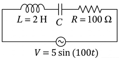
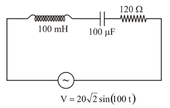
We are told that the applied alternating emf is $$e = e_0 \sin(100t)$$, where the time $$t$$ is in seconds.
Comparing $$e = e_0 \sin(\omega t)$$ with the standard form $$e = e_0 \sin(\omega t)$$, we recognise that the angular frequency is
$$\omega = 100\ \text{rad s}^{-1}\,.$$
The circuit to be chosen must give a phase difference of
$$\phi = \frac{\pi}{4} = 45^\circ$$
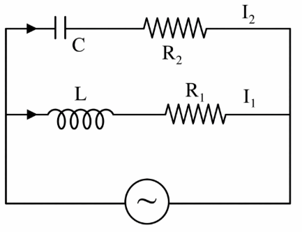
between the applied emf $$e$$ and the current $$i$$. We therefore examine how the phase angle arises in series $$RC$$ and $$RL$$ circuits.
For a series RC circuit the impedance is
$$Z = R - jX_C = R - j\frac{1}{\omega C},$$
so the phase of the impedance (with respect to the real axis) is
$$\theta = -\tan^{-1}\!\!\left(\frac{X_C}{R}\right) = -\tan^{-1}\!\!\left(\frac{1}{\omega R C}\right).$$
Because the current leads the voltage by the magnitude of this angle, the current-voltage phase difference is
$$\phi_{RC} = \tan^{-1}\!\!\left(\frac{1}{\omega R C}\right).$$
For a series RL circuit the impedance is
$$Z = R + jX_L = R + j\omega L,$$
so the phase of the impedance is
$$\theta = \tan^{-1}\!\!\left(\frac{X_L}{R}\right)=\tan^{-1}\!\!\left(\frac{\omega L}{R}\right).$$
This time the current lags the voltage by the same magnitude, giving
$$\phi_{RL} = \tan^{-1}\!\!\left(\frac{\omega L}{R}\right).$$
In both cases we require the magnitude of the phase angle to be
$$\phi = \frac{\pi}{4}\,,$$
which implies
$$\tan\phi = 1.$$
We now check each option.
Option A: RC circuit, $$R = 1\ \text{k}\Omega = 10^3\ \Omega$$, $$C = 1\ \mu\text{F} = 10^{-6}\ \text{F}$$.
Using $$\tan\phi = \dfrac{1}{\omega R C}$$, we have
$$\tan\phi_A = \frac{1}{(100)(10^3)(10^{-6})} = \frac{1}{0.1} = 10.$$
Since $$\tan\phi_A = 10 \neq 1$$, the phase angle is not $$\pi/4$$. This option is rejected.
Option B: RL circuit, $$R = 1\ \text{k}\Omega = 10^3\ \Omega$$, $$L = 1\ \text{mH} = 10^{-3}\ \text{H}$$.
Using $$\tan\phi = \dfrac{\omega L}{R}$$, we have
$$\tan\phi_B = \frac{(100)(10^{-3})}{10^3} = \frac{0.1}{10^3} = 1\times10^{-4}.$$
Since $$\tan\phi_B \neq 1$$, the required phase difference is not obtained. This option is rejected.
Option C: RL circuit, $$R = 1\ \text{k}\Omega = 10^3\ \Omega$$, $$L = 10\ \text{mH} = 10^{-2}\ \text{H}$$.
Again using $$\tan\phi = \dfrac{\omega L}{R}$$,
$$\tan\phi_C = \frac{(100)(10^{-2})}{10^3} = \frac{1}{10^3} = 0.001.$$
This is still far from unity, so the phase angle is not $$\pi/4$$. This option is also rejected.
Option D: RC circuit, $$R = 1\ \text{k}\Omega = 10^3\ \Omega$$, $$C = 10\ \mu\text{F} = 10^{-5}\ \text{F}$$.
Using $$\tan\phi = \dfrac{1}{\omega R C}$$, we get
$$\tan\phi_D = \frac{1}{(100)(10^3)(10^{-5})} = \frac{1}{1} = 1.$$
Because $$\tan\phi_D = 1$$, we have
$$\phi_D = \tan^{-1}(1) = 45^\circ = \frac{\pi}{4}.$$
This is exactly the required phase difference. Therefore option D satisfies the given condition.
Hence, the correct answer is Option D.