The current I em units, flowing in a coil of a tangent galvanometer is given by the expression where
r = Mean radius of the galvanometer coil.
N = Numberof turns of the galvanometercoil.
H = Horizontal componentof earth magneticfield.
$$\phi$$ = Deflection of galvanometer magnetic needle.
ISRO Scientist or Engineer Electrical 2015
For the following questions answer them individually
To measure current, Ammeters are connected in
If a circuit is formed consisting of two dissimilar metallic conductors, and if one of the junction has a temperature of 71 and the other is at higher temperature 72, a current flow in the circuit. This effect is called as
Two wattmeter connected to measure the input of a balanced 3 Phasecircuit indicates 2000 Watts and 500 Watts respectively. What will be the power factor of the circuit when
both of the readings are positive?
Wheatstone Bridge is used for measurementof
In a series RLC circuit, during resonance
Which of the following network theorem deals with finding out the circuit values of voltage and current in a restricted portion of the network by replacing the actual source of energy by a single “equivalent voltage source” or by a single “equivalent current source” acting at a terminal pair?
What will be the base impedance for a three phase system with base MVA = 100 MVA and . Base kV as 11 kV?
The differential protection relay may lose its stability for through faults due to saturation of CT magnetic circuit during short circuit condition. To overcome this difficulty which of the following technique is used
During single phasing, the unbalanced stator current have a negative sequence component, which cause
The Burden ofprotective Current Transformer (CT) is specified in
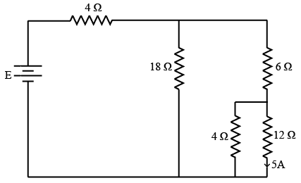
In the network shown in the figure below, the current in the 12 Ohm resistor is 5 Amps, the battery voltage E is
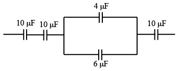
What is the equivalent capacitance of the following circuit?
The relation between the flux density (B) and Magnetic field intensity (H) is given by $$B = \mu H$$. What is $$\mu$$ in this relation?
Powersupply to a 10 pole induction motor is supplied by 4 pole alternator which is driven at 1500 RPM. If the motor runs with slip of 4%, whatis its speed?
A power factor meter connected in a circuit indicates pf of 0.6 lagging. To improve the power factor, we have to insert the following componentin the circuit.
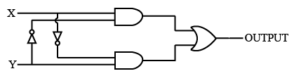
The logic evaluated by the circuit at the output is
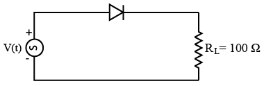
The figure shows a half wave rectifier circuit with input voltage $$U(t) = 10 \sin (100 \pi t)$$ volts. Assuming ideal diode characteristics with zero forward voltage drop and zero reverse current, the average power consumed in watts by the load resistance RL is
The truth table
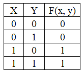
Represent the Boolean function
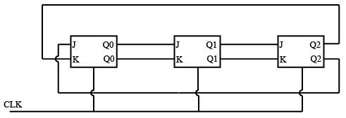
A three stage Johnson counter ring in figure is clocked at a constant frequency of $$f_c$$. from starting state of $$Q_0, Q_1, Q_2 = 101$$. The frequencyof output $$Q_0, Q_1, Q_2,$$ will be
A 4 bit module — 16 ripple counter uses JK F/F. If the propagation delay of each F/F is 50 nano seconds, the maximum clock frequency that can be used is equal to
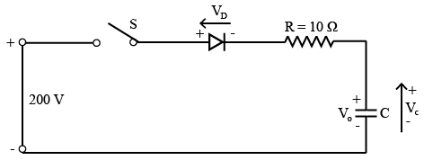
Figure shown below, capacitor is initially charged to $$V_o = 50 V$$ with upper plate positive. Switch S is closed at t = 0. Current through the circuit at t = 0 and final voltage across C are respectively
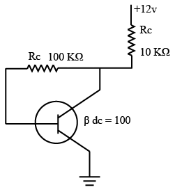
The Q point value $$I_c$$ for the circuit is
The frequency of oscillations of transistorized Colpitts Oscillator having tank circuit parameters $$C1 = 150 pF, C2 = 1.5 nf$$ and $$L = 50 \mu H$$ is
The following distortion readings are available for a power amplifier. D2 = 0.2, D3 = 0.02 and vD4 = 0.06. The Total Harmonic Distortion (THD)is
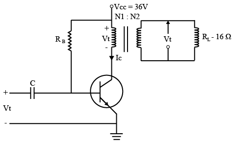
A transformer coupled class A amplifier drives a 16 Ohm loud speaker through 4:1 transformer with $$V_{cc} = 36 V$$. If the circuit delivers 2 Watts to load, the rms voltage across the load assuming transformer efficiency as 100 % is
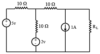
In the $$R_L$$ circuit given below, the maximum power will be transferred when value of $$R_L$$ is
A-source $$V_s(t) = V \cos 100 \pi t$$ has an internal impedance of $$(4 + j3) Ω$$. If a purely resistive load is connected to this source has to extract the maximum powerout of the source, its value in Ohms should be
In a transformer, exciting current is made up of two components namely magnetizing current Im and core loss current Ic, with negligible leakage impedance drop (V is supply voltage)
The leakage flux in a transformer depends upon
If Excitation of synchronous generator fails, it acts as a
In a tap changer, the voltage at consumer terminals is kept within the prescribed limits by varying the
The residual magnetism of a self excited DC generatoris lost. To build up its emf what to be done to regain the residual magnetism?
Two DC series machines are mechanically coupled. One machine is running as a motor and the other as a generator. The iron andfriction loss will be identical when
The phaser diagram of a synchronous machine connected to an infinite bus is shown below. The machine is

A 3 phase synchronous motor, connected to aninfinite bus, operating at a leading pf with a constant load torque, if excitation is increased ($$\delta$$ is load angle and $$\phi$$ power factor angle)
Magnetizing in rush current in transformeris rich in
Two Induction motors A and B are identical except that the air gap of motor ‘A’ is 50% greater than that of motor B then
A 3 phase induction motor draws active power P and reactive power Q from grid. If it is operating as a generator, P and Q will respectively be
In case of 3 Phase Short circuit in a system, the power fed into the system is
The output voltage of the ideal transformer with polarities and dots shown in the figure is given by

The average real power in watts delivered to a load impedance $$ZL = (4 - J2)Ω$$ by an ideal current source $$i(t) = 4 \sin(\omega t + 20^\circ)A$$ is
A network contains B branches and N Nodes. The number of mesh current equations would be
Superposition theorem is valid for
Asine wave as has a peak value of 12 Volts. Its crest factor is
A sinusoidal voltage $$V = 50 \sin \omega t$$ is applied to a series RL circuit. The currentin the circuit is given by $$I = 25 \sin(\omega t - 53^\circ)$$. The apparent power consumed by the load is
A band pass filter is one which
A bulb in staircase has two switches, one switch being at the ground floor and the other being at first floor. The bulb can be turned ON and also OFF by any one of the switch
irrespective of the state of the other switch. The logic of switching of bulb resembles
Time domain expressionsfor the voltage $$V_1(t)$$ and $$V_2(t)$$ is given by
$$V_1(t) = V_m \sin(10 t - 130^\circ)$$ and $$V_2(t) = V_m \cos(10 t + 10^\circ)$$ which is the correct statement
The anticlockwise direction of rotation of phasor may be taken as positive.
In practice, earth is chosen as a place of zero electric potential because it
Series compensation on EHV lines is resorted to
The magnetic susceptibility of a specimen is small and positive, the specimen is
The rate of rise of restriking voltage depends upon
A Digital Volt Meter (DVM) uses 10 MHz clock and hasa voltage controlled generator which provides a width of $$5 \mu$$ sec/volt of unit signal. A 10 V input signal would correspond to a pulse count of
In figure shown below, the Peak Inverse Voltage (PIV) required for diode is

A practical current source consists of
The transient current in a loss free LC circuit when excited from an AC source results in ..................... sine wave.
The transport layer protocol used for real time multimedia, file transfer, DNS and e-mail respectively are
Techniques that automatically move program and data blocks into physical main memory when they are required for execution are called
Resistor of microprocessor $$(\mu P)$$ which keeps track of the execution of program and which contain the memory address of next instruction to be executed is called
OS that permits multiples programs to run simultaneously using single processoris referred as
The cladding which surrounds the optic fiber line is used
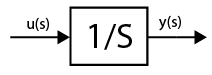
Assuming zero initial condition, the response y(t) of the system given below to a unit step input u(t) is
If the unit step response of a network is $$(1 - e^{-at})$$ then its unit impulse response is
The solution of the differential equation $$\left(\frac{dy}{dx}\right) = ky, Y(0) = C$$ is
The trigonometric Fourier series of an even function does not have the
If $$x = \sqrt{-1}$$ then the value of $$x^x$$ is
For the function $$f(t) = e^{\frac{-t}{r}}$$, the Taylor series approximation for $$t << \tau$$ is
If the impedance of an AC circuit is $$10 \angle 60^\circ Ω$$ then resistance in the circuit is
The dielectric strength of air under normal condition is
String efficiency of 100% meansin string insulators
To limit current chopping in Vacuum Circuit Breakers (VCB), the contact material used has
In a three phase four wire unbalanced system, the current in the neutral wire is 18 A. The magnitude of zero sequence current is
The positive $$(Z_1)$$, negative $$(Z_2)$$ and zero $$(Z_0)$$ sequence impedances of a solidly grounded system under steady state condition always follow the relation
Eddy currentloss in core of a transformer is
The square root of $$64 \angle 36^\circ$$
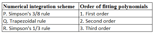
Match the correct pairs :
What is Laplace Transform of $$(\sin h(at))$$?
If a phasor is multiplied by j then
If two complex numbersare equal