Intext Questions (Fractals)
1
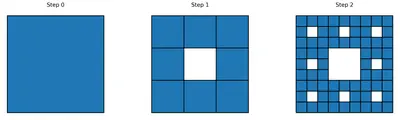
By its construction, each step in the sequence has
- squares of the same size that remain in the figure, and the size of these squares becomes smaller and smaller as the step number increases, and
- square holes that are formed by removing square pieces.

Solution
Step 0: Draw a single square. Take its side length to be $$1$$ unit.
Step 1: Divide the square into a $$3\times 3$$ grid of $$9$$ smaller squares, each of side $$\tfrac{1}{3}$$. Remove (colour black) the middle square. The figure now has $$8$$ squares of side $$\tfrac{1}{3}$$ remaining, and $$1$$ square hole in the centre.
Step 2: Apply the same rule to each of the $$8$$ remaining squares. Each is divided into a $$3\times 3$$ grid of squares of side $$\tfrac{1}{9}$$, and the middle square of each is removed. Every one of the $$8$$ squares contributes $$1$$ new hole and leaves $$8$$ smaller squares behind. So Step 2 has
$$8\times 8 \;=\; 64$$ small squares of side $$\tfrac{1}{9}$$ remaining, together with the $$1$$ big central hole of Step 1 and the $$8$$ new smaller holes formed in Step 2.
Continuing this rule at every step gives the successive figures that approach the Sierpinski Carpet.
Answer
2 Do you see any pattern in the number of holes and squares that remain at each step?
Solution
Let $$R_n$$ denote the number of squares that remain at Step $$n$$ and $$H_n$$ the total number of holes at Step $$n$$. Tabulating the first few values gives:
| Step $$n$$ | Squares remaining $$R_n$$ | Holes $$H_n$$ |
|---|---|---|
| $$0$$ | $$1$$ | $$0$$ |
| $$1$$ | $$8$$ | $$1$$ |
| $$2$$ | $$64$$ | $$9$$ |
| $$3$$ | $$512$$ | $$73$$ |
Squares. Every square that survives at Step $$n-1$$ is divided into $$9$$ tiny squares and $$1$$ of them is removed, so $$8$$ tiny squares survive from each. Hence
$$R_n \;=\; 8\cdot R_{n-1}.$$
Starting from $$R_0 = 1$$ this gives $$R_n = 8^n$$ — the sequence $$1,\,8,\,64,\,512,\,\ldots$$ is a geometric progression with common ratio $$8$$.
Holes. At Step $$n$$ we introduce one new hole for every square that was present at Step $$n-1$$. So the number of new holes at Step $$n$$ is $$R_{n-1}=8^{n-1}$$, and the total is
$$H_n \;=\; H_{n-1} + 8^{n-1}.$$
This gives $$H_n = 1 + 8 + 8^2 + \cdots + 8^{n-1}$$, a geometric sum whose terms grow by a factor $$8$$ each step.
Answer
3 Can this be used to get a formula for $$R_n$$?
Solution
Yes. From the pattern of the previous question, every square that remains at Step $$n-1$$ is replaced by $$8$$ smaller squares at Step $$n$$, so
$$R_n \;=\; 8\cdot R_{n-1}.$$
Starting from $$R_0 = 1$$ and applying this rule repeatedly,
$$R_1 = 8\cdot 1 = 8,\qquad R_2 = 8\cdot 8 = 8^{2},\qquad R_3 = 8\cdot 8^{2} = 8^{3},\ \ldots$$
In general,
\[ \boxed{\,R_n \;=\; 8^{\,n}\,} \]
Check: $$R_0 = 8^{0} = 1$$, $$R_1 = 8$$, $$R_2 = 64$$, $$R_3 = 512$$ — exactly the values we tabulated.
Answer
4 Similarly, how do we find the number of holes at a given step?
Solution
At Step $$n$$ each surviving square from Step $$n-1$$ produces exactly one new hole (the middle piece that we remove). So the count of new holes introduced at Step $$n$$ is $$R_{n-1} = 8^{\,n-1}$$, and the total count of holes is
$$H_n \;=\; H_{n-1} + R_{n-1} \;=\; H_{n-1} + 8^{\,n-1}.$$
Starting from $$H_0 = 0$$ and applying this rule,
$$H_n \;=\; 1 + 8 + 8^{2} + \cdots + 8^{\,n-1}.$$
This is a geometric series with first term $$1$$, common ratio $$8$$, and $$n$$ terms. Using the geometric sum formula,
\[ H_n \;=\; \frac{8^{\,n}-1}{8-1} \;=\; \frac{8^{\,n}-1}{7}. \]
Check: $$H_1 = \tfrac{8-1}{7} = 1$$, $$H_2 = \tfrac{64-1}{7} = 9$$, $$H_3 = \tfrac{512-1}{7} = 73$$ — matching the tabulated values.
Answer
5 Show that by joining the midpoints of an equilateral triangle, we divide it into 4 identical equilateral triangles. [Hint: Note that the corner triangles are isosceles.]
Solution
Let $$\triangle ABC$$ be equilateral with side length $$s$$, so $$AB = BC = CA = s$$ and $$\angle A = \angle B = \angle C = 60^{\circ}$$. Let $$D,\,E,\,F$$ be the midpoints of $$BC,\,CA,\,AB$$ respectively. Joining $$D,E,F$$ creates $$4$$ smaller triangles inside $$\triangle ABC$$ — three at the corners ($$\triangle AFE,\ \triangle BFD,\ \triangle CED$$) and one in the middle ($$\triangle DEF$$).
1. The corner triangles are equilateral. Look at $$\triangle AFE$$. Since $$F$$ is the midpoint of $$AB$$ and $$E$$ is the midpoint of $$AC$$,
$$AF \;=\; \tfrac{1}{2}AB \;=\; \tfrac{s}{2},\qquad AE \;=\; \tfrac{1}{2}AC \;=\; \tfrac{s}{2}.$$
So $$AF = AE$$, i.e. $$\triangle AFE$$ is isosceles with apex angle $$\angle A = 60^{\circ}$$. The two base angles are equal and together with $$60^{\circ}$$ sum to $$180^{\circ}$$, so each base angle is $$\tfrac{180^{\circ}-60^{\circ}}{2} = 60^{\circ}$$. All three angles of $$\triangle AFE$$ are $$60^{\circ}$$, so it is equilateral with side $$\tfrac{s}{2}$$.
The same argument applied at vertices $$B$$ and $$C$$ shows that $$\triangle BFD$$ and $$\triangle CED$$ are also equilateral with side $$\tfrac{s}{2}$$.
2. The middle triangle is equilateral. By the midpoint theorem, the segment joining the midpoints of two sides of a triangle is parallel to the third side and half its length. Applying this to $$\triangle ABC$$:
$$EF \;=\; \tfrac{1}{2}BC \;=\; \tfrac{s}{2},\qquad FD \;=\; \tfrac{1}{2}CA \;=\; \tfrac{s}{2},\qquad DE \;=\; \tfrac{1}{2}AB \;=\; \tfrac{s}{2}.$$
All three sides of $$\triangle DEF$$ equal $$\tfrac{s}{2}$$, so it is equilateral with side $$\tfrac{s}{2}$$.
3. Conclusion. All four triangles $$\triangle AFE,\ \triangle BFD,\ \triangle CED,\ \triangle DEF$$ are equilateral and have the same side length $$\tfrac{s}{2}$$. Hence they are identical (congruent). $$\blacksquare$$
Answer
Figure it Out (Sierpinski Triangle)
1 Draw the initial few steps (at least till Step 2) of the shape sequence that leads to the Sierpinski Triangle.
Solution
Step 0: Draw a single equilateral triangle. Call its side length $$1$$ unit.
Step 1: Mark the midpoints of the three sides and join them. By Question 5 above, this splits the triangle into $$4$$ smaller identical equilateral triangles, each of side $$\tfrac{1}{2}$$: three of them point up (at the corners) and one points down (in the middle). Remove the middle downward-pointing triangle. Now $$3$$ upward triangles remain, and there is $$1$$ triangular hole.
Step 2: Apply the same rule to each of the $$3$$ remaining upward triangles. Each one is split into $$4$$ triangles of side $$\tfrac{1}{4}$$ and its central downward triangle is removed. Each contributes $$3$$ smaller triangles and $$1$$ new hole. So Step 2 has
$$3\times 3 \;=\; 9$$ upward triangles of side $$\tfrac{1}{4}$$ remaining, together with the $$1$$ large hole from Step 1 and $$3$$ new smaller holes formed in Step 2 (total $$4$$ holes).
Continuing the same procedure at every step yields the successive figures that approach the Sierpinski Triangle.
Answer
2 Find the number of holes, and the triangles that remain at each step of the shape sequence that leads to the Sierpinski Triangle.
Solution
Let $$T_n$$ be the number of (upward) triangles remaining at Step $$n$$, and $$H_n$$ be the total number of holes at Step $$n$$.
Remaining triangles. Every triangle at Step $$n-1$$ is split into $$4$$ smaller ones and its central (downward) triangle is removed, so exactly $$3$$ small upward triangles survive from each. Hence
$$T_n \;=\; 3\cdot T_{n-1}, \qquad T_0 = 1.$$
Iterating gives
\[ T_n \;=\; 3^{\,n}. \]
Holes. At Step $$n$$ we punch out exactly one new hole for every upward triangle present at Step $$n-1$$, so the number of new holes added is $$T_{n-1} = 3^{\,n-1}$$, and
$$H_n \;=\; H_{n-1} + 3^{\,n-1}, \qquad H_0 = 0.$$
Summing gives a geometric series:
$$H_n \;=\; 1 + 3 + 3^{2} + \cdots + 3^{\,n-1} \;=\; \frac{3^{\,n}-1}{3-1} \;=\; \frac{3^{\,n}-1}{2}.$$
| Step $$n$$ | Triangles $$T_n = 3^{\,n}$$ | Holes $$H_n = \tfrac{3^{\,n}-1}{2}$$ |
|---|---|---|
| $$0$$ | $$1$$ | $$0$$ |
| $$1$$ | $$3$$ | $$1$$ |
| $$2$$ | $$9$$ | $$4$$ |
| $$3$$ | $$27$$ | $$13$$ |
| $$4$$ | $$81$$ | $$40$$ |
Answer
3 Find the area of the region remaining at the $$n$$th step in each of the shape sequences that lead to the Sierpinski fractals. Take the area of the starting square/triangle to be 1 sq. unit.
Solution
Let $$A_n$$ denote the area remaining at Step $$n$$, with $$A_0 = 1$$ sq. unit for the starting figure.
(a) Sierpinski Carpet. Each square at Step $$n-1$$ is divided into $$9$$ smaller squares of equal area, and $$1$$ of them (the middle one) is removed. So each square keeps $$\tfrac{8}{9}$$ of its area. The total surviving area is therefore multiplied by $$\tfrac{8}{9}$$ at every step:
$$A_n \;=\; \tfrac{8}{9}\cdot A_{n-1}.$$
Iterating from $$A_0 = 1$$,
\[ \boxed{\,A_n \;=\; \left(\tfrac{8}{9}\right)^{n}\ \text{sq. units}\,}. \]
Check: $$R_n = 8^{n}$$ small squares each of side $$\left(\tfrac{1}{3}\right)^{n}$$ and area $$\left(\tfrac{1}{9}\right)^{n}$$ give total area $$8^{n}\cdot \tfrac{1}{9^{n}} = \left(\tfrac{8}{9}\right)^{n}.$$
(b) Sierpinski Triangle. Each triangle at Step $$n-1$$ is divided into $$4$$ smaller equilateral triangles of equal area (see Question 5), and $$1$$ of them (the central one) is removed. So each triangle keeps $$\tfrac{3}{4}$$ of its area. Therefore
$$A_n \;=\; \tfrac{3}{4}\cdot A_{n-1}, \qquad A_0 = 1.$$
Iterating,
\[ \boxed{\,A_n \;=\; \left(\tfrac{3}{4}\right)^{n}\ \text{sq. units}\,}. \]
Check: $$T_n = 3^{n}$$ triangles each of side $$\left(\tfrac{1}{2}\right)^{n}$$ and area $$\left(\tfrac{1}{4}\right)^{n}$$ give total area $$3^{n}\cdot\tfrac{1}{4^{n}} = \left(\tfrac{3}{4}\right)^{n}.$$
In both cases the surviving area shrinks geometrically, and as $$n$$ grows without bound it approaches $$0$$ — the Sierpinski fractals have area $$0$$ in the limit even though infinitely many pieces remain.
Answer
Figure it Out (Koch Snowflake)
1 Draw the initial few steps (at least till Step 2) of the shape sequence that leads to the Koch Snowflake.
Solution
Step 0: Draw an equilateral triangle. Take its side to be $$1$$ unit; then the shape has $$3$$ sides and perimeter $$3$$.
Step 1: Take each of the $$3$$ straight sides and modify it by the following rule — divide the side into three equal parts, then on the middle third construct an outward-pointing equilateral bump (a small equilateral triangle) and delete the middle third itself. What was one straight edge of length $$1$$ has become $$4$$ smaller edges of length $$\tfrac{1}{3}$$ each. Doing this on every side of Step 0 turns the triangle into a six-pointed star with
$$3\times 4 \;=\; 12\ \text{sides},$$
each of length $$\tfrac{1}{3}$$.
Step 2: Apply the same rule to each of the $$12$$ sides. Every side splits into $$4$$ new sides of length $$\tfrac{1}{9}$$ each, giving
$$12\times 4 \;=\; 48\ \text{sides},$$
each of length $$\tfrac{1}{9}$$. The outline now has many more small triangular bumps sitting on the earlier bumps.
Continuing this rule at every step gives the successive figures whose limit is the Koch Snowflake.
Answer
2 Find the number of sides in the $$n$$th step of the shape sequence that leads to the Koch Snowflake.
Solution
Let $$S_n$$ denote the number of sides in the outline of the Step-$$n$$ shape. In the rule for building the next step, every single side is replaced by $$4$$ new sides. So
$$S_n \;=\; 4\cdot S_{n-1}.$$
Starting from $$S_0 = 3$$ (the three sides of the initial equilateral triangle) and applying the rule,
$$S_1 = 4\cdot 3 = 12, \qquad S_2 = 4\cdot 12 = 48, \qquad S_3 = 4\cdot 48 = 192, \ \ldots$$
In general,
\[ \boxed{\,S_n \;=\; 3\cdot 4^{\,n}\,}. \]
| Step $$n$$ | $$0$$ | $$1$$ | $$2$$ | $$3$$ | $$4$$ |
|---|---|---|---|---|---|
| Sides $$S_n$$ | $$3$$ | $$12$$ | $$48$$ | $$192$$ | $$768$$ |
Answer
3 Find the perimeter of the shape at the $$n$$th step of the sequence. Take the starting equilateral triangle to have a sidelength of 1 unit.
Solution
At Step $$n$$, every side has length $$\ell_n$$ and the number of sides is $$S_n$$. The perimeter is $$P_n = S_n\cdot \ell_n$$.
Length of one side. In the rule, each side is divided into three equal parts, so the new side length is $$\tfrac{1}{3}$$ of the previous one. Starting from $$\ell_0 = 1$$,
$$\ell_n \;=\; \left(\tfrac{1}{3}\right)^{n}.$$
Number of sides. From the previous question,
$$S_n \;=\; 3\cdot 4^{\,n}.$$
Perimeter. Multiplying,
$$P_n \;=\; S_n\cdot \ell_n \;=\; 3\cdot 4^{\,n}\cdot \left(\tfrac{1}{3}\right)^{n} \;=\; 3\cdot \frac{4^{\,n}}{3^{\,n}}.$$
\[ \boxed{\,P_n \;=\; 3\cdot\left(\tfrac{4}{3}\right)^{n}\ \text{units}\,}. \]
| Step $$n$$ | $$0$$ | $$1$$ | $$2$$ | $$3$$ |
|---|---|---|---|---|
| $$P_n$$ | $$3$$ | $$4$$ | $$\tfrac{16}{3} \approx 5.33$$ | $$\tfrac{64}{9} \approx 7.11$$ |
Because the factor $$\tfrac{4}{3} > 1$$, the perimeter grows without bound as $$n\to\infty$$ — the Koch Snowflake has infinite perimeter although it encloses only a finite area.
Answer
Intext Questions (Visualising Solids and Making Solids)
6 We will start this section by practising visualisation. For each prompt, feel free to talk to your partner, gesture, draw it in the air—but do not actually draw on paper!
1. Picture your name, then read off the letters backwards. Make sure to do this by sight, not by sound—really see your name! Now try with your friend's name.
Solution
This is a pure visualisation exercise — nothing is drawn or written.
How to do it. Close your eyes and imagine your name written on a page in front of you. Do not spell it aloud in your mind; instead look at the imagined letters. Now let your gaze travel from the last letter to the first, reading each letter as you go.
Example. If your name is ANITA, then reading the letters right-to-left you see A, T, I, N, A. If your friend's name is RAVI, you see I, V, A, R.
The point of the exercise is to notice that you are using a picture in your head, not the sound of the name — the two skills are different, and geometry needs the picture-in-the-head skill.
Answer
2. Cut off the four corners of an imaginary square, with each cut going between midpoints of adjacent edges. What shape is left over? How can you reassemble the four corners to make another square?
Solution
Let the square $$ABCD$$ have side $$2$$ units, and let $$P,Q,R,S$$ be the midpoints of $$AB,BC,CD,DA$$ respectively.
The four corner pieces. Each cut goes from the midpoint of one side to the midpoint of the adjacent side, so at each corner we remove a right-angled isosceles triangle. For example the corner cut at $$B$$ removes $$\triangle PBQ$$, which has legs $$BP = BQ = 1$$ and a right angle at $$B$$. Its hypotenuse is
$$PQ \;=\; \sqrt{1^{2}+1^{2}} \;=\; \sqrt{2}\ \text{units}.$$
All four corner pieces are congruent right-angled isosceles triangles with legs $$1$$ and hypotenuse $$\sqrt{2}$$.
What remains. The middle shape is the quadrilateral $$PQRS$$ whose sides are all $$\sqrt{2}$$ (each was the hypotenuse of a corner cut). By symmetry of the construction all four angles at $$P,Q,R,S$$ are equal, and since the total is $$360^{\circ}$$ each is $$90^{\circ}$$. So $$PQRS$$ is a square of side $$\sqrt{2}$$, rotated $$45^{\circ}$$ relative to the original.
Its area is $$\left(\sqrt{2}\right)^{2} = 2$$ square units, exactly half the area of the original ($$4$$ square units), as expected.
Reassembling the four corners. Take the four triangular pieces and place them hypotenuse-to-hypotenuse, matching one hypotenuse of length $$\sqrt{2}$$ against another. Two triangles put together along their hypotenuse make a $$1\times 1$$ square (since each is half of a unit square). Doing this with the two pairs makes two $$1\times 1$$ squares, and placing them side by side makes a $$1\times 2$$ rectangle. To make a single square instead, arrange the four right-angled triangles so that their right angles all meet at one point and their legs form the sides of a new square: the four legs of length $$1$$ form the perimeter, giving a square of side $$1+1 = ?$$ — in fact you get a square of side $$\sqrt{2}$$ with total area $$2$$ square units.
So the four corners reassemble into a square of side $$\sqrt{2}$$ — a copy of the middle square that was left behind. Together the middle square and the reassembled corner square account for the original area $$2+2 = 4$$.
Answer
3. Mark the sides of an equilateral triangle into thirds. Cut off each corner of the triangle, as far as the marks. What shape do you get?
Solution
Let $$\triangle ABC$$ be equilateral with side $$3$$ units. On each side mark the two points that divide it into three equal parts. Label the trisection points on:
- $$AB$$ as $$P$$ (near $$A$$) and $$Q$$ (near $$B$$), with $$AP = QB = 1$$ and $$PQ = 1$$;
- $$BC$$ as $$R$$ (near $$B$$) and $$S$$ (near $$C$$), with $$BR = SC = 1$$ and $$RS = 1$$;
- $$CA$$ as $$T$$ (near $$C$$) and $$U$$ (near $$A$$), with $$CT = UA = 1$$ and $$TU = 1$$.
Cutting the corner at $$A$$ as far as the marks removes $$\triangle AUP$$. This triangle has $$AU = AP = 1$$ and $$\angle A = 60^{\circ}$$, so it is isosceles with apex $$60^{\circ}$$, hence equilateral of side $$1$$. In particular $$UP = 1$$. The same argument applies at $$B$$ (giving $$QR = 1$$) and at $$C$$ (giving $$ST = 1$$).
The remaining shape. After removing the three corner triangles, the boundary of what is left is the hexagon $$P\,Q\,R\,S\,T\,U$$. Its six sides are
$$PQ = 1,\ QR = 1,\ RS = 1,\ ST = 1,\ TU = 1,\ UP = 1.$$
All sides are equal. Now the interior angles: the interior angle at $$Q$$ lies between edge $$PQ$$ (a piece of the original side $$AB$$) and edge $$QR$$ (a cut across corner $$B$$). Since $$\triangle BQR$$ has $$BQ = BR = 1$$ and $$\angle B = 60^{\circ}$$ (equilateral again), its base angle at $$Q$$ is $$60^{\circ}$$. So the interior angle of the hexagon at $$Q$$ is
$$180^{\circ} - 60^{\circ} \;=\; 120^{\circ}.$$
By symmetry, the interior angles at $$P,R,S,T,U$$ are all $$120^{\circ}$$ too. A hexagon with all sides equal and all interior angles $$120^{\circ}$$ is a regular hexagon.
Answer
4. Mark the sides of a square into thirds and cut off each of its corners as far as the marks. What shape is left?
Solution
Let the square have side $$3$$ units. Mark each side into three equal parts, so on every side there are two trisection points. At each corner the two adjacent trisection points sit at a distance $$1$$ from the corner along each of the two sides.
Cutting the corner as far as those marks removes a right-angled triangle with legs $$1$$ and $$1$$, right-angled at the corner. Its hypotenuse — the cut itself — has length
$$\sqrt{1^{2}+1^{2}} \;=\; \sqrt{2}\ \text{units}.$$
The same happens at every corner, so four congruent right-angled isosceles triangles are removed.
What remains. The boundary of the remaining shape is an octagon (8 sides): four sides are the untouched middle thirds of the original sides (each of length $$1$$), and four sides are the diagonal cuts (each of length $$\sqrt{2}$$). These two side-lengths alternate around the boundary. Every interior angle of the octagon equals
$$180^{\circ} - 45^{\circ} \;=\; 135^{\circ},$$
because at every vertex a right-angled isosceles triangle with base angle $$45^{\circ}$$ has been cut away.
So the octagon is equiangular (all angles $$135^{\circ}$$) but not equilateral — its sides alternate between $$1$$ and $$\sqrt{2}$$. It is not a regular octagon (a regular octagon would need equal side lengths, which would require cutting off segments of length $$\tfrac{3}{2+\sqrt{2}}$$, not $$1$$).
Answer
7 Can you describe a solid and a viewpoint that would result in each of the following cases? If it helps, you can imagine the solid passing through a wall like Tom did, and leaving a hole of the appropriate shape.
5. A solid whose profile has a square outline
Solution
Any solid whose "silhouette" from the given viewpoint fits exactly inside a square works. Two easy examples:
- A cube, viewed head-on (looking straight at any of its six faces). The silhouette against the wall is exactly one square face.
- A square prism (a cuboid whose base is a square) viewed from the direction that faces the square base. Again the outline is that square.
In each case the light rays travel perpendicular to the wall; every ray touches the solid somewhere, and the boundary of the shadow region is a square.
Answer
6. A solid whose profile has a circular outline
Solution
Two easy examples:
- A sphere — from any viewpoint the outline is a circle whose radius equals the radius of the sphere.
- A cylinder viewed along its axis, i.e. looking straight at one of its circular ends. The silhouette is exactly that circular face.
Similarly, a cone viewed along its axis (looking straight at the base) produces a circular outline.
Answer
7. A solid whose profile has a triangular outline
Solution
Two easy examples:
- A cone viewed from the side (looking perpendicular to its axis). The silhouette is an isosceles triangle whose base is a diameter of the cone and whose apex is the tip of the cone.
- A triangular prism viewed straight at one of its two triangular ends. The silhouette is that triangular end.
A pyramid (with any polygonal base) viewed from a suitable side also gives a triangular profile.
Answer
8
Spend some time on this, and if you are finding it difficult to visualise, you may look around and use objects that are around you, or that you will make in the next section. Feel free to consider viewpoints from any direction, including directly above the object.
8. A solid with a rectangular profile from one viewpoint and a circular profile from another viewpoint
Solution
A cylinder works perfectly. Suppose it has base radius $$r$$ and height $$h$$.
- Viewed along its axis (i.e. looking straight at one of the two circular faces), the outline is a circle of radius $$r$$.
- Viewed perpendicular to its axis (i.e. looking at the curved side), the outline is a rectangle of width $$2r$$ and height $$h$$.
Everyday examples: a tin can, a candle, a cold-drink can, a pencil (before the tip is sharpened).
Answer
9. A solid with a circular profile from one viewpoint and a triangular one from another viewpoint
Solution
A cone works. Suppose it has base radius $$r$$ and slant height $$\ell$$.
- Viewed along its axis from below (looking straight at the circular base), the outline is a circle of radius $$r$$.
- Viewed perpendicular to its axis (i.e. from the side), the outline is an isosceles triangle whose base is $$2r$$ and whose two equal slanted sides have length $$\ell$$.
Everyday examples: an ice-cream cone, a birthday-party hat, a road-work traffic cone.
Answer
10. A solid with a rectangular profile from one viewpoint and a triangular one from another viewpoint
Solution
A triangular prism works. It has two congruent triangular ends joined by three rectangular side faces.
- Viewed straight at one of the triangular ends, the outline is that triangle.
- Viewed at right angles to one of the rectangular side faces, the outline is that rectangle.
Everyday examples: a glass prism used to split light, a Toblerone chocolate box, the ridge of a tent.
Answer
11. A solid with a trapezium shaped profile from one viewpoint and a circular one from another viewpoint
Solution
A frustum of a cone (a cone whose top has been sliced off parallel to its base) works. Its two circular faces have different radii — a larger one at the bottom and a smaller one at the top — joined by a curved slanted surface.
- Viewed along its axis from above (or below), the outline is a circle (the larger circular face).
- Viewed perpendicular to its axis (from the side), the outline is an isosceles trapezium whose longer parallel side is the diameter of the base and shorter parallel side is the diameter of the top.
Everyday examples: a bucket, a cup or a tumbler, a flower pot.
Answer
12. A solid with a pentagonal profile from one viewpoint and a rectangular one from another viewpoint
Solution
A pentagonal prism works. It has two congruent pentagonal end faces joined by five rectangular side faces.
- Viewed straight at one of the pentagonal ends, the outline is that pentagon.
- Viewed at right angles to any of the rectangular side faces, the outline is that rectangle.
Everyday examples: the wooden pencils that have a pentagonal cross-section, or a small hut whose front is shaped like a house (a rectangle with a triangular roof — the "house" outline is a pentagon).
Answer
9 Are there unique solids for each of the conditions, or can you come up with multiple possibilities?
Solution
The solids are not unique. For any given combination of two profiles, many different solids can produce them, because the profile only records the outline of the shadow — it does not tell us anything about what the object looks like on the inside or between its two views. Some illustrations:
- Rectangle + circle. Not only a cylinder — a cylinder with a hollow through the middle (a pipe), a cylinder wrapped around some spikes, or even a cone joined to another cone base-to-base, all give a rectangular side view and a circular end view (or at least give the same outline shadow).
- Circle + triangle. A cone works, but so does a cone glued to a hemisphere at its base (like an ice-cream on a cone), and so does a bicone (two cones joined at the base — the side view is a rhombus, but the outline of a cone glued to a cylinder-with-conical-top can still give a triangular silhouette).
- Rectangle + triangle. A triangular prism works, but so does a wedge, a "tent" (a rectangular box with a triangular prism on top), or a chocolate bar with a triangular ridge along the top.
- Trapezium + circle. A frustum of a cone works, but so does a "stepped" solid made by stacking cylinders of different radii — the outline from the side approximates a trapezium.
- Pentagon + rectangle. A pentagonal prism works, but so does a house-shaped tent (a cuboid with a triangular prism on top) and a variety of asymmetric solids.
In general, the profile from one viewpoint captures only how the object "covers up" the wall behind it; many different three-dimensional shapes cast the same outline. That is why an object's three orthographic views (front, top, side together) still may not determine the solid uniquely.
Answer
10 If the congruent polygons of a prism have 10 sides, how many faces, edges and vertices does the prism have? What if the polygons have $$n$$ sides?
Solution
A prism whose top and bottom are congruent $$n$$-sided polygons is built like this:
- the top face is an $$n$$-gon,
- the bottom face is a congruent $$n$$-gon (directly below the top),
- each side of the top polygon is joined to the corresponding side of the bottom polygon by a rectangular lateral face — so there are $$n$$ such rectangles.
Faces. Add up: $$1$$ top + $$1$$ bottom + $$n$$ lateral rectangles
$$F \;=\; n + 2.$$
Edges. The top polygon contributes $$n$$ edges; the bottom polygon contributes $$n$$ edges; and there are $$n$$ vertical edges joining corresponding vertices of the two polygons. In total
$$E \;=\; n + n + n \;=\; 3n.$$
Vertices. Every vertex of the top polygon is a vertex of the prism, and so is every vertex of the bottom polygon — with no extra vertices anywhere else. So
$$V \;=\; n + n \;=\; 2n.$$
Check with Euler's formula: $$V - E + F = 2n - 3n + (n+2) = 2$$. ✓
Case $$n = 10$$. Substituting,
$$F = 12, \qquad E = 30, \qquad V = 20.$$
| 10-sided prism | $$n$$-sided prism | |
|---|---|---|
| Faces | $$12$$ | $$n+2$$ |
| Edges | $$30$$ | $$3n$$ |
| Vertices | $$20$$ | $$2n$$ |
Answer
11 If the base of a pyramid has 10 sides, how many faces, edges and vertices does the pyramid have? What if the base is an $$n$$-sided polygon?
Solution
A pyramid whose base is an $$n$$-sided polygon is built like this:
- the base is an $$n$$-gon,
- a single point (the apex) lies above the base, joined by a straight edge to every vertex of the base — so each edge of the base together with the two edges from its endpoints to the apex bounds a triangular lateral face.
Faces. $$1$$ base + $$n$$ triangular lateral faces
$$F \;=\; n + 1.$$
Edges. $$n$$ edges of the base + $$n$$ "slant" edges from base vertices to the apex
$$E \;=\; n + n \;=\; 2n.$$
Vertices. $$n$$ base vertices + $$1$$ apex
$$V \;=\; n + 1.$$
Check with Euler's formula: $$V - E + F = (n+1) - 2n + (n+1) = 2$$. ✓
Case $$n = 10$$. Substituting,
$$F = 11, \qquad E = 20, \qquad V = 11.$$
| 10-sided base | $$n$$-sided base | |
|---|---|---|
| Faces | $$11$$ | $$n+1$$ |
| Edges | $$20$$ | $$2n$$ |
| Vertices | $$11$$ | $$n+1$$ |
Answer
12 What is a net of a cube?
Solution
A net of a solid is a flat (two-dimensional) arrangement of polygons that share edges, in such a way that, when we fold the arrangement along the shared edges, it wraps up perfectly to form the solid — with no gaps, no overlaps and no missing faces.
A cube has $$6$$ square faces. So a net of a cube is a plane figure made of six congruent squares joined edge to edge, arranged in such a way that folding along the joining edges creates a closed cube.
The most familiar example is the "plus-sign" net: four squares in a row, with one extra square attached to the top of the second square and one attached to the bottom of the second square. Folding along the shared edges tucks the outer four squares up around a central square, closing the top with the sixth.
Not every arrangement of six squares is a valid net. For instance, six squares arranged in a $$2\times 3$$ rectangle cannot be folded into a cube. In all, a cube has exactly $$11$$ distinct nets (up to rotations and reflections).
Answer
13 Visualise how it can be folded to form a cube.
Solution
Take the standard "plus-sign" net of a cube: a strip of four squares $$S_1S_2S_3S_4$$ placed side by side in a row, with an extra square $$S_5$$ attached to the top of $$S_2$$ and an extra square $$S_6$$ attached to the bottom of $$S_2$$.
To visualise the folding, do it step by step. Fix square $$S_2$$ flat on the table — it will become the bottom of the cube.
- Fold $$S_1$$ up along the edge shared with $$S_2$$ through a right angle — it becomes the left face.
- Fold $$S_3$$ up along its edge with $$S_2$$ — it becomes the right face.
- Fold $$S_5$$ up along its edge with $$S_2$$ — it becomes the back face.
- Fold $$S_6$$ up along its edge with $$S_2$$ — it becomes the front face.
- Now $$S_4$$ (which is joined to $$S_3$$) folds up over the top and closes the cube — it becomes the top face.
Every one of the newly meeting edges (for example, the top edge of $$S_1$$ meeting the left edge of $$S_5$$) coincides in length because all $$6$$ squares are congruent, so the box seals shut without gaps or overlaps — giving a perfect cube.
You can convince yourself further by cutting the net out of paper and folding it: the whole action takes only $$5$$ folds, one for each of the $$5$$ shared edges that are not part of the base $$S_2$$.
Answer
Figure it Out (Nets of a Cube and Cuboid)
1 Which of the following are the nets of a cube? First, try to answer by visualisation. Then, you may use cutouts and try. (Six candidate arrangements of six joined squares, labelled (i)–(vi), are shown.)
Solution
A cube has $$6$$ congruent square faces, so a candidate has at least to be made of $$6$$ squares joined edge to edge. But not every such arrangement folds up into a cube. There is a very useful rule of thumb: if any "column" of the arrangement contains four squares in a straight row, and the remaining two squares are attached one on each side of the four-in-a-row (or attached higher and lower on the row, as long as they are not both on the same square), then it usually folds up into a cube; if the arrangement contains a $$2\times 2$$ block of squares, or four squares in a $$2\times 2$$ arrangement, it cannot fold up.
Working through the six candidates in the figure:
- (i) Four squares in a row with one square attached on top of the second and one attached on the bottom of the third. Folding: the four in a row wrap around to form four vertical faces; the extra top square lands on the top; the extra bottom square lands on the bottom. ✓ Is a net.
- (ii) A "plus sign" — four squares surrounding a central square, plus one more attached to one of the four. This folds up so that the central square is the bottom, four surrounding squares are the four vertical faces, and the last square closes the top. ✓ Is a net.
- (iii) Contains a $$2\times 2$$ block of squares. In any cube net, two squares in a $$2\times 2$$ block would have to be the same face (top or bottom) of the cube, which is impossible. ✗ Not a net.
- (iv) Three squares in a row, with three more squares stacked (all on the same square) above (or below). Folding gives an overlap of two squares on one face. ✗ Not a net.
- (v) Three squares in a row with two squares attached on top of the middle square (stacked). This causes two squares to fold onto the top face, leaving one face uncovered. ✗ Not a net.
- (vi) Two rows of three, offset by one square (a "$$Z$$"-shape). Four of the squares form a strip that wraps around; the extra two attach so that one becomes the top and one becomes the bottom. ✓ Is a net.
You can verify by cutting each arrangement out of paper and trying to fold it — the ones that pass are the true nets of a cube.
Rule of thumb used above. An arrangement of six squares is a cube net if and only if (a) it contains no $$2\times 2$$ block of squares, and (b) when a longest straight strip of squares is chosen, the remaining squares are attached one per side of that strip (never two on the same square, never two on the same side of the strip in the same position).
Answer
2 A cube has 11 possible net structures in total. In this count, two nets are considered the same if one can be obtained from the other by a rotation or a flip. For example, the following nets are all considered the same — (three equivalent net arrangements are shown). Find all the 11 nets of a cube.
Solution
It is convenient to sort the $$11$$ nets by the length of the longest straight strip of squares that appears in them. That length can be $$4$$, $$3$$ or $$2$$.
Family A — a straight strip of $$4$$ squares (six nets in all). Place the strip horizontally as squares $$1,2,3,4$$ from left to right. The remaining two squares must be attached above or below this strip, one at a time, and never both attached to the same square (otherwise they would overlap when folded).
- A1. One square above square $$1$$ and one below square $$1$$ — the "$$L$$" shape.
- A2. One square above square $$1$$ and one below square $$2$$.
- A3. One square above square $$1$$ and one below square $$3$$.
- A4. One square above square $$1$$ and one below square $$4$$ — the "$$Z$$" or step-shape.
- A5. One square above square $$2$$ and one below square $$2$$ — the classic "plus/cross" net.
- A6. One square above square $$2$$ and one below square $$3$$ — the "$$T$$" shape.
(Positions such as "above $$3$$ and below $$2$$" are the reflection of A6, hence the same net; and "above $$2$$ and below $$1$$" is the reflection of A2 — likewise not new.)
Family B — the longest strip has length $$3$$ (three nets). Place a strip of three horizontally, squares $$1,2,3$$. Two more squares are attached above (or below) forming a strip of length $$2$$; the sixth square attaches to complete the arrangement.
- B1. Squares $$4$$ and $$5$$ sitting above squares $$1$$ and $$2$$, and square $$6$$ sitting below square $$3$$.
- B2. Squares $$4$$ and $$5$$ sitting above squares $$1$$ and $$2$$, and square $$6$$ sitting below square $$2$$.
- B3. Squares $$4$$ and $$5$$ sitting above squares $$2$$ and $$3$$, and square $$6$$ sitting below square $$1$$.
Family C — the longest strip has length $$3$$ with two squares each on top and bottom (two nets).
- C1. Strip of $$3$$ horizontally; two squares above squares $$1$$ and $$2$$; one square below square $$3$$; one square attached to the right of the top strip.
- C2. Strip of $$3$$ with a "staircase": one square above squares $$2$$ and $$3$$ and one below squares $$1$$ and $$2$$.
Together, Families A, B, C give $$6+3+2 = 11$$ distinct nets — that is all of them. (Any other arrangement of $$6$$ squares either produces one of these under a rotation/flip, or contains a $$2\times 2$$ block, and hence cannot be a net of a cube.)
How to draw them. On squared paper, draw the eleven arrangements described above. To verify, cut each out and fold it into a cube.
Answer
3 Draw a net of a cuboid having sidelengths:
(i) 5 cm, 3 cm, and 1 cm
Solution
A cuboid of sides $$5\ \mathrm{cm}\times 3\ \mathrm{cm}\times 1\ \mathrm{cm}$$ has six rectangular faces that come in three congruent pairs:
- Two "top/bottom" faces of size $$5\times 3$$ (each $$15\ \mathrm{cm}^{2}$$),
- Two "front/back" faces of size $$5\times 1$$ (each $$5\ \mathrm{cm}^{2}$$),
- Two "left/right" faces of size $$3\times 1$$ (each $$3\ \mathrm{cm}^{2}$$).
How to draw the net (a "cross" layout). Start with a rectangle $$ABCD$$ of size $$5\times 3$$ in the middle of the sheet — this is the bottom face. Attach the other rectangles to its four sides as follows:
- Along $$AB$$ (the top edge, length $$5$$): draw a rectangle $$5\ \mathrm{cm}\times 1\ \mathrm{cm}$$ pointing upward — the back face.
- Along $$CD$$ (the bottom edge, length $$5$$): draw another $$5\ \mathrm{cm}\times 1\ \mathrm{cm}$$ rectangle pointing downward — the front face.
- Along $$AD$$ (the left edge, length $$3$$): draw a $$3\ \mathrm{cm}\times 1\ \mathrm{cm}$$ rectangle pointing left — the left face.
- Along $$BC$$ (the right edge, length $$3$$): draw a $$3\ \mathrm{cm}\times 1\ \mathrm{cm}$$ rectangle pointing right — the right face.
- Finally attach a $$5\ \mathrm{cm}\times 3\ \mathrm{cm}$$ rectangle on the far edge of the back face (i.e. above the rectangle in step $$1$$) — the top face.
The whole layout looks like a "cross". When you cut it out and fold along the shared edges, the four side rectangles fold up to become the four vertical faces, and the extra rectangle above closes the box on top — giving a cuboid of the required size.
Check the shared edges: the edge along which the top face (step $$5$$) folds onto the back face has length $$5\ \mathrm{cm}$$; the edge where the top face meets the front face has length $$5\ \mathrm{cm}$$; the edges where the top face meets the left/right faces have length $$3\ \mathrm{cm}$$. In every case matching edges are equal — the net folds up without any gap or overlap.
Answer
(ii) 6 cm, 3 cm, and 2 cm
Solution
A cuboid of sides $$6\ \mathrm{cm}\times 3\ \mathrm{cm}\times 2\ \mathrm{cm}$$ has three pairs of rectangular faces:
- Two "top/bottom" faces of size $$6\times 3$$ (each $$18\ \mathrm{cm}^{2}$$),
- Two "front/back" faces of size $$6\times 2$$ (each $$12\ \mathrm{cm}^{2}$$),
- Two "left/right" faces of size $$3\times 2$$ (each $$6\ \mathrm{cm}^{2}$$).
How to draw the net (a "strip-plus-top-and-bottom" layout). First lay the four vertical faces side by side as a long strip whose height is the cuboid's height, $$2\ \mathrm{cm}$$:
- Draw a rectangle $$6\ \mathrm{cm}\times 2\ \mathrm{cm}$$ — the front face.
- To its right, share the vertical edge to draw a $$3\ \mathrm{cm}\times 2\ \mathrm{cm}$$ rectangle — the right face.
- To the right of that, share the vertical edge to draw a $$6\ \mathrm{cm}\times 2\ \mathrm{cm}$$ rectangle — the back face.
- To the right of that, share the vertical edge to draw a $$3\ \mathrm{cm}\times 2\ \mathrm{cm}$$ rectangle — the left face.
The total strip is thus $$18\ \mathrm{cm}\times 2\ \mathrm{cm}$$ (since $$6+3+6+3 = 18$$). Now attach the two remaining rectangles:
- Above the front face, share its top horizontal edge (length $$6$$) to draw a $$6\ \mathrm{cm}\times 3\ \mathrm{cm}$$ rectangle — the top face.
- Below the front face, share its bottom horizontal edge (length $$6$$) to draw another $$6\ \mathrm{cm}\times 3\ \mathrm{cm}$$ rectangle — the bottom face.
When you cut the whole figure out and fold along the vertical shared edges, the four rectangles of the horizontal strip form the four vertical faces of the cuboid; when you also fold along the horizontal edges of the front face, the top and bottom rectangles fold up (and down) to close the box. Every matching edge has equal length — the folded shape is a $$6\ \mathrm{cm}\times 3\ \mathrm{cm}\times 2\ \mathrm{cm}$$ cuboid without any gaps or overlaps.
Answer
Intext Questions (Nets of Solids, Shortest Paths, and Projections)
14 What is a net of a regular tetrahedron? Which of the following are nets of a regular tetrahedron? (Four candidate arrangements of equilateral triangles are shown.)
Solution
A regular tetrahedron is a solid bounded by $$4$$ congruent equilateral triangular faces. Every vertex is the meeting point of $$3$$ of these triangles.
A net of a regular tetrahedron is a flat arrangement of $$4$$ congruent equilateral triangles joined along their edges, which can be folded up along those edges to close up into the tetrahedron with no gaps or overlaps.
For an arrangement of four equilateral triangles to fold up into a tetrahedron, the arrangement should not contain the "forbidden" sub-shapes (a large equilateral triangle of side $$2$$, made from four small triangles — because then the flat figure is already a triangle and there is nothing to fold; or a strip of $$4$$ triangles all pointing the same way, which folds to overlap).
Working through the four candidates typically shown in the figure:
- (a) The classic "strip" (a triangle with three others attached to its three sides). This is the standard net. It folds up by lifting the three outer triangles until their outer vertices meet at a common apex. ✓ Is a net.
- (b) A "zig-zag" strip of four triangles, alternately pointing up and down. When folded, the two outer triangles wrap around and their far edges meet, closing the tetrahedron. ✓ Is a net.
- (c) A larger equilateral triangle made of four small equilateral triangles (the "Step 1 of the Sierpinski triangle" layout). Because it already lies as a triangle in the plane, folding along any of the internal edges only lifts three of the small triangles above the fourth — but then their outer vertices meet at a single apex directly above the central triangle. ✓ Is a net.
- (d) Any arrangement with a $$2\times 2$$ block of four small triangles all pointing in the same direction, or with fewer than $$4$$ triangles, or with $$4$$ triangles attached in a way that would require an overlap when folded. ✗ Not a net.
So, in a typical NCERT layout, three of the four candidate arrangements are valid nets (the strip, the zig-zag, and the "big triangle of four"), while the fourth cannot be folded into a tetrahedron.
Answer
15 Are there any other possible nets?
Solution
Yes. A regular tetrahedron has more than one net, but not many. If we treat two nets as the same when one can be turned into the other by a rotation or a flip, then there are exactly two distinct nets of a regular tetrahedron:
- The "big triangle" net. Four equilateral triangles arranged so that they together form a single larger equilateral triangle of side twice as long (the central triangle points down and the three surrounding triangles point up).
- The "strip" net. Four equilateral triangles arranged in a strip that alternately points up and down (like a zig-zag ribbon), forming a parallelogram-shaped outline.
Every other flat arrangement of four congruent equilateral triangles either turns out to be a rotation or reflection of one of these two, or cannot be folded into a tetrahedron at all. So $$2$$ is the total number of distinct nets of a regular tetrahedron.
Answer
16 Draw a net with appropriate measurements that can be folded into a regular tetrahedron. Verify if it works by making an actual cutout.
Solution
Choose the edge length of the tetrahedron, say $$a = 5\ \mathrm{cm}$$. Every face is an equilateral triangle of side $$5\ \mathrm{cm}$$, so every triangle in the net has all three sides equal to $$5\ \mathrm{cm}$$ and all three angles equal to $$60^{\circ}$$.
Construction of the "big triangle" net. Using a ruler and a compass:
- Draw a segment $$AB$$ of length $$2a = 10\ \mathrm{cm}$$ horizontally.
- With the compass, mark two arcs of radius $$2a = 10\ \mathrm{cm}$$ — one centred at $$A$$ and one centred at $$B$$. They meet at a point $$C$$ above the line. Draw $$CA$$ and $$CB$$. Triangle $$ABC$$ is equilateral with side $$10\ \mathrm{cm}$$.
- Mark the midpoints $$P$$ of $$AB$$, $$Q$$ of $$BC$$ and $$R$$ of $$CA$$. Draw $$PQ$$, $$QR$$ and $$RP$$.
By the midpoint theorem, $$\triangle APR,\ \triangle PBQ,\ \triangle RQC$$ and $$\triangle PQR$$ are each equilateral with side $$5\ \mathrm{cm}$$ — exactly $$4$$ equilateral triangles of side $$5\ \mathrm{cm}$$, forming the big-triangle net.
Folding check. Cut along the outer boundary of $$\triangle ABC$$. The central triangle $$\triangle PQR$$ will be the base of the tetrahedron. Fold the three outer triangles $$\triangle APR,\ \triangle PBQ,\ \triangle RQC$$ upward along $$RP,\ PQ,\ QR$$ respectively. The three outer vertices $$A,B,C$$ all rise until they meet at a single point above the centre of $$\triangle PQR$$ — because each outer triangle has an edge of length $$5$$ opposite to the corresponding vertex of the base, and all three outer triangles are congruent. Their meeting point is the apex of the tetrahedron.
The result is a regular tetrahedron of edge $$5\ \mathrm{cm}$$. If you actually cut out this net from paper and fold it, you can hold it in your hand and confirm the fit.
Answer
17 Draw a net with appropriate measurements that can be folded into a square pyramid. Verify if it works by making an actual cutout.
Solution
A square pyramid has one square base and four congruent triangular faces that meet at a common apex above the base. To draw a net, choose a base side and a slant edge — for instance, base side $$a = 4\ \mathrm{cm}$$ and slant edge $$\ell = 5\ \mathrm{cm}$$ (so each triangular face is an isosceles triangle with base $$4\ \mathrm{cm}$$ and equal sides $$5\ \mathrm{cm}$$).
Construction.
- Draw a square $$ABCD$$ of side $$4\ \mathrm{cm}$$.
- On the outside of each side of the square, construct an isosceles triangle with base equal to that side and the two equal sides of length $$5\ \mathrm{cm}$$. To draw the triangle on side $$AB$$: with the compass, mark an arc of radius $$5\ \mathrm{cm}$$ from $$A$$ and another of radius $$5\ \mathrm{cm}$$ from $$B$$ on the opposite side of $$AB$$ from the square. They meet at a point $$P$$. Join $$AP$$ and $$BP$$. Triangle $$APB$$ has $$AP = BP = 5\ \mathrm{cm}$$.
- Repeat step $$2$$ for the other three sides $$BC, CD, DA$$, obtaining apex points $$Q, R, S$$.
The whole outline consists of the square $$ABCD$$ with four congruent triangles attached, one on each side — a "plus-sign" shaped net.
Folding check. Cut the net out. Keep the square flat; fold the four triangles upward along the sides of the square. Because they are all congruent isosceles triangles with equal sides $$5\ \mathrm{cm}$$, the four apex points $$P,Q,R,S$$ rise until they coincide at a single point above the centre of the square — the apex of the pyramid. The height $$h$$ of the pyramid is
$$h \;=\; \sqrt{\ell^{2}-\left(\tfrac{a}{2}\right)^{2} - \left(\tfrac{a}{2}\right)^{2}}\;=\;\sqrt{25 - 4 - 4}\;=\;\sqrt{17}\ \mathrm{cm}\approx 4.12\ \mathrm{cm}.$$
The net folds perfectly, producing a square pyramid with base $$4\ \mathrm{cm}\times 4\ \mathrm{cm}$$ and slant edge $$5\ \mathrm{cm}$$.
Answer
18 What is the net of a cylinder?
Solution
A right circular cylinder of base radius $$r$$ and height $$h$$ has three faces:
- a bottom face — a circular disc of radius $$r$$,
- a top face — a circular disc of radius $$r$$,
- a curved lateral surface — this surface, when slit vertically along one straight line and unrolled, opens out into a flat rectangle.
So the net of a cylinder consists of two congruent circular discs and one rectangle joined to the circumference of one of the discs. The most familiar drawing places the rectangle in the middle with a circle attached above and another circle attached below.
When we roll the rectangle back into a tube (bringing its two vertical edges together) and cap each open end with one of the circles, we recover the cylinder.
Answer
19 What are the sidelengths of the rectangle obtained?
Solution
Imagine unrolling the curved surface of a cylinder of radius $$r$$ and height $$h$$ by slitting it vertically along one straight line and laying it flat. Two things happen:
- The vertical direction is preserved — the height of the rectangle is the height $$h$$ of the cylinder.
- The horizontal direction (once curled around the cylinder) becomes the boundary circle at the top or bottom. Its total length is the circumference of that circle,
$$\text{circumference}\;=\;2\pi r.$$
So the rectangle has
$$\text{width}\;=\;2\pi r,\qquad \text{height}\;=\;h.$$
For example, a cylinder of radius $$7\ \mathrm{cm}$$ and height $$10\ \mathrm{cm}$$ gives a rectangle of dimensions $$2\pi\cdot 7 = 14\pi \approx 44\ \mathrm{cm}$$ by $$10\ \mathrm{cm}$$.
Answer
20 How will the net of a cone look?
Solution
A right circular cone of base radius $$r$$ and slant height $$\ell$$ has two faces:
- a base — a circular disc of radius $$r$$,
- a curved lateral surface — this surface, when slit along a straight slant line from the apex to the base and then unrolled, opens out into a flat sector (a "pizza slice") of a circle.
The sector has centre at what used to be the apex of the cone. Its two straight edges are two copies of the slant line — both of length $$\ell$$. The curved edge of the sector is what used to be the boundary circle of the base of the cone; when we roll the sector back up, this curved edge closes into the base circle.
So the net of a cone consists of two pieces: a sector of radius $$\ell$$, together with a circular disc of radius $$r$$ joined to the curved edge of the sector.
Answer
21 If the cone is slit open along the line $$l$$ and then unrolled, what will we get?
Solution
Slitting the curved surface of the cone from its apex along a slant line $$l$$ to the boundary of the base, and then flattening it, gives a sector of a circle (a "pizza-slice" region).
- The centre of this sector is what used to be the apex of the cone.
- Its two straight sides are two copies of the slant edge $$l$$, so both have length equal to the slant height $$\ell$$ of the cone.
- Its curved side (the arc) is the boundary circle of the base of the cone laid out flat. Hence the arc length equals the base circumference:
$$\text{arc length}\;=\;2\pi r.$$
If we let $$\theta$$ (in radians) be the angle of the sector at its centre, then the arc length of a sector of radius $$\ell$$ is $$\ell\,\theta$$. Setting this equal to $$2\pi r$$ gives
$$\theta \;=\; \frac{2\pi r}{\ell}\ \text{radians}\;=\;\frac{r}{\ell}\cdot 360^{\circ}.$$
So the sector has radius $$\ell$$ and central angle $$\dfrac{r}{\ell}\cdot 360^{\circ}$$. This is exactly the "pizza-slice" you get when you unroll the curved surface of the cone.
Answer
22 What surface do you construct by using the above net, in which O is not the centre of the boundary circle? Make a physical model to help you answer this question!
Solution
In the "usual" cone-net, the apex point $$O$$ is placed at the centre of the boundary circle of the base — every straight line from $$O$$ to the boundary has the same length (the slant height $$\ell$$), so when we roll it up we get a right circular cone: a cone whose apex sits directly above the centre of the circular base.
If instead we take a net in which $$O$$ is not at the centre of the boundary circle, then the distances from $$O$$ to points on the boundary vary — some slant lines are longer, some are shorter. Rolling the sector up (bringing the two straight edges together) still produces a curved surface with a single apex, and the boundary still closes into a circle. But because the slant lengths are not all equal, the apex ends up not directly above the centre of the circle — the apex leans over to one side.
Such a solid is called an oblique cone (a slanted cone). Its base is still a circle, but its apex is off-centre. A physical model (which you can make from paper) confirms this: cut a sector, mark a point $$O$$ inside it that is not the centre of the boundary arc, then roll it up. You will hold in your hand a cone-like surface that leans, like a tilted party hat.
Answer
23 Draw a net with appropriate measurements that can be folded into a triangular prism. Verify that it works by making an actual cutout.
Solution
A triangular prism has $$2$$ congruent triangular ends and $$3$$ rectangular lateral faces. Let us make one whose ends are equilateral triangles of side $$a = 4\ \mathrm{cm}$$ and whose length (height of the prism) is $$h = 6\ \mathrm{cm}$$. Then the three rectangular lateral faces are all $$4\ \mathrm{cm}\times 6\ \mathrm{cm}$$.
Construction of the net.
- Draw a rectangle $$R_{1}$$ of size $$4\ \mathrm{cm}\times 6\ \mathrm{cm}$$ — one lateral face.
- To its right, sharing the vertical edge (of length $$6\ \mathrm{cm}$$), draw another $$4\ \mathrm{cm}\times 6\ \mathrm{cm}$$ rectangle $$R_{2}$$.
- To the right of that, sharing the vertical edge, draw a third $$4\ \mathrm{cm}\times 6\ \mathrm{cm}$$ rectangle $$R_{3}$$. Now we have a horizontal strip $$12\ \mathrm{cm}\times 6\ \mathrm{cm}$$ split into three rectangles.
- Along the top edge of $$R_{2}$$ (a segment of length $$4\ \mathrm{cm}$$), construct an equilateral triangle upward with all sides $$4\ \mathrm{cm}$$ — this will be one triangular end of the prism.
- Along the bottom edge of $$R_{2}$$ (also a segment of length $$4\ \mathrm{cm}$$), construct another equilateral triangle downward with all sides $$4\ \mathrm{cm}$$ — the other triangular end.
The net is now complete: three side-by-side rectangles with an equilateral triangle attached above the middle rectangle and another below.
Folding check. Cut the net out. Keep $$R_{2}$$ flat. Fold $$R_{1}$$ and $$R_{3}$$ upward along the shared vertical edges of $$R_{2}$$ so that they rise perpendicular to $$R_{2}$$. Their far vertical edges (the outer edges of $$R_{1}$$ and $$R_{3}$$) now sit above $$R_{2}$$. Fold the top triangle downward along its shared edge with $$R_{2}$$, and fold the bottom triangle upward — the two triangles meet exactly the tops (respectively bottoms) of $$R_{1}$$ and $$R_{3}$$ because the triangle side ($$4\ \mathrm{cm}$$) matches the vertical edges of $$R_{1}$$ and $$R_{3}$$. The net closes to form a triangular prism with an equilateral triangle of side $$4\ \mathrm{cm}$$ as its cross-section, and length $$6\ \mathrm{cm}$$.
Answer
24 Taking all the triangles in the net to be equilateral, make a cutout of the net and fold it to form an octahedron.
Solution
A regular octahedron has $$8$$ faces, each an equilateral triangle. At every vertex, $$4$$ of these triangles meet. Choose the edge length, say $$a = 4\ \mathrm{cm}$$.
Drawing the net. A common net of the octahedron is a "strip of $$8$$ triangles" arranged in two rows of $$4$$ triangles that alternately point up and down.
- Draw a horizontal segment of length $$4a = 16\ \mathrm{cm}$$. This will be the top boundary of the strip.
- Divide it into $$4$$ equal parts of $$4\ \mathrm{cm}$$ each, marking the interior points.
- Below this segment, construct $$4$$ equilateral triangles pointing downward with side $$4\ \mathrm{cm}$$, using the four segments as bases.
- Between them (upside down relative to those), construct $$3$$ more equilateral triangles of side $$4\ \mathrm{cm}$$ so that together they tile the strip as a row of $$7$$ triangles alternately down and up.
- Similarly attach another row of $$7$$ alternating triangles below. In total there are $$8$$ triangles (the correct number for an octahedron).
[An alternative simple net: two rows of four equilateral triangles arranged like a "zig-zag ribbon", with the boundaries and connectivity chosen so that the $$8$$ triangles can be folded into an octahedron. The key idea is that every fold line will become an edge of the octahedron, and the four triangles at each vertex must meet at a common point after folding.]
Folding. Cut along the outer boundary. Fold the triangles up and down along the shared edges, one pair at a time. After folding, the free edges of triangles that were at the outer boundary of the net meet exactly in pairs — because there are always an even number of triangles to meet at each vertex and their edges are all of the same length. The final closed shape has $$8$$ triangular faces, $$12$$ edges, and $$6$$ vertices (four triangles meeting at each vertex) — a regular octahedron.
Making a paper cutout and folding is the fastest way to verify this: you can put the octahedron on its side and see the two "square pyramids" that share a square base — which is another way to visualise the octahedron.
Answer
25 Net of a sphere? Experiment and see if you can make a paper cutout that can perfectly wrap around a ball without leaving any wrinkles, gaps or overlaps.
Solution
Try it and see: no flat paper cutout will perfectly wrap around a sphere. However carefully you cut and arrange the paper, you will end up with either wrinkles (where the paper "bunches" because there is too much of it), overlaps (where paper crosses over itself), gaps (where paper is missing), or all three.
The reason is a deep fact about the geometry of the sphere: it is curved in two directions at every point, whereas a piece of paper is flat. To lay a piece of paper on a sphere without stretching or tearing it, you would need the sphere to be "developable" — the mathematical name for a surface that can be laid flat without any distortion. Cylinders and cones are developable (their curved surfaces really do open into a rectangle and a sector), but the sphere is not developable.
This is exactly why every world map (a flat picture of the round Earth) has to distort something: distances, areas, or angles cannot all be preserved at the same time. Traditional atlases "chop up" the sphere into orange-peel-like strips called gores, which come close to the shape but still leave gaps between neighbouring pieces.
Answer
26 What is the shortest path for the ant to reach the laddu? (The laddu is at the centre of the top face of a cuboid and the ant is at the centre of an adjacent side face.)
Solution
Idea: "unfold" the cuboid. The ant walks along the surface of the cuboid. Any path along the surface stays on two adjacent faces (a side face and the top face), which meet along a common edge. If we "unfold" the two faces about their common edge so that they lie in one flat plane, then any path along the surface unrolls into a curve in the plane joining the ant to the (unrolled) laddu. Among all curves in a plane between two points, the straight line segment is the shortest. So the shortest path on the surface is the one whose unfolding is that straight line segment.
Applying this to our cuboid. Unfold the side face on which the ant sits and the top face on which the laddu sits, about the top edge they share. The ant is at the centre of the side face, and the laddu is at the centre of the top face; after unfolding, both centres are marked on a single flat rectangle formed by the union of the two faces. Draw the straight line segment from ant to laddu on this flat rectangle. That straight line is the shortest path.
Then re-fold the side face back into place. The line segment now becomes a bent path along the surface, going straight across the side face until it meets the top edge, and then straight across the top face to the laddu. Its total length is the same as the length of the straight line segment in the unfolded diagram (folding does not change lengths).
Formula. Suppose the cuboid has the side face measuring $$L\times H$$ (width $$L$$ along the top edge, height $$H$$) and the top face measuring $$L\times W$$ (same width $$L$$, other side $$W$$). The ant is at the centre of the side face, so its distance from the shared top edge is $$\tfrac{H}{2}$$. The laddu is at the centre of the top face, so after unfolding its distance from the same edge is $$\tfrac{W}{2}$$ on the other side. Both are exactly halfway along the shared edge (at $$\tfrac{L}{2}$$ from either end), so on the unfolded rectangle they lie on the same perpendicular to the shared edge. The straight-line distance is
$$\text{shortest path}\;=\;\frac{H}{2}+\frac{W}{2}\;=\;\frac{H+W}{2}.$$
So the ant walks straight up its side face to the middle of the top edge, then straight across the top face to the laddu; the total length is $$\tfrac{H+W}{2}$$.
Answer
27 What about in the following case? (The laddu is at the centre of an edge of the cuboid, and the ant is on a side face.)
Solution
The same "unfold and draw a straight line" idea works. The laddu sits on an edge of the cuboid, which is a boundary of two adjacent faces at the same time — so once we unfold either of those two faces to lie flat with the ant's face, we can join the ant to the laddu by a straight segment.
Step 1. Identify the two adjacent faces of the cuboid on which the shortest path lies: the ant's side face and (one of) the face(s) meeting the ant's face along the edge that contains the laddu. Both these faces share the edge where the laddu sits.
Step 2. Unfold the ant's face and this adjacent face about their common edge so that they lie flat in one plane. Mark the ant's position on the ant's face; the laddu is on the shared edge itself. Draw the straight line segment joining the ant to the laddu — this segment lies inside the ant's face (because the laddu is on its boundary), so it is a straight line entirely in one face.
Step 3. Since the straight line lies inside the ant's face, folding does not change it: the ant simply walks in a straight line along its own side face to the laddu on the edge. Its length is the straight-line distance from the ant to the laddu on the flat rectangle of the ant's face.
Formula. Say the ant's side face is a rectangle of size $$L\times H$$. Suppose the ant is at position $$(x_{a},y_{a})$$ on this face and the laddu sits at the midpoint of one of the four edges of this face — that is, at one of $$(\tfrac{L}{2},0), (\tfrac{L}{2},H), (0,\tfrac{H}{2}), (L,\tfrac{H}{2})$$. Then
$$\text{shortest path}\;=\;\sqrt{(x_{a}-x_{\text{laddu}})^{2}+(y_{a}-y_{\text{laddu}})^{2}}.$$
For example, if the ant sits at the centre of a $$4\ \mathrm{cm}\times 6\ \mathrm{cm}$$ face and the laddu is at the midpoint of the top edge, then the ant is at $$(2,3)$$, the laddu is at $$(2,6)$$, and the shortest path is $$\sqrt{0+9}=3\ \mathrm{cm}$$ — a straight vertical walk of $$3\ \mathrm{cm}$$.
Answer
28 If we think that a certain path is the shortest, how can we be sure that it truly is, among all the infinite possibilities?
Solution
We use the following simple fact about the plane, which we already know:
Among all curves in a plane joining two given points, the straight line segment joining them is the shortest.
To apply this to a path on the surface of a cuboid, we unfold the two (or more) faces that the path uses about their common edges, so that they lie in one flat plane. Unfolding does not stretch, tear or fold the surface, so the length of a path on the surface is exactly equal to the length of its image in the unfolded diagram.
Now our path, in its unfolded form, is a curve in the plane between two points. If it is a straight line segment and lies entirely inside the unfolded region, then by the fact above it is the shortest such curve — and hence the corresponding path on the cuboid is the shortest path.
If our candidate curve is not a straight line segment in the unfolded picture, then it is not the shortest. We may need to try different unfoldings — the ant can travel via different pairs (or triples) of faces, and different unfoldings can give straight lines of different lengths. The true shortest path is the shortest among all those straight-line lengths.
So the strategy is: (1) list the reasonable ways the path can travel across faces; (2) for each, unfold the faces flat and draw the straight line; (3) compute the straight-line lengths; (4) pick the smallest. This turns an "infinite" problem into a small, finite computation.
Answer
29 For example, are either of these the shortest path? (Two candidate paths from the ant to the laddu on the surface of the cuboid are shown.)
Solution
To check, unfold the two adjacent faces the path travels on into one flat plane, and see whether the drawn path is a straight line joining the ant to the laddu.
Path 1. The ant walks up its side face to the top edge, then across the top face to the laddu. When we unfold these two faces about their shared top edge, the drawn path becomes a bent broken line (with a kink where it meets the fold). Between the same two end-points there is always a strictly shorter path in the plane — namely the straight line segment. So this "up then across" broken-line path is not the shortest.
Path 2. Similarly, the second candidate path (e.g. one that first goes horizontally along the side face, then vertically upward, then across the top face) will unfold into another broken line. It, too, is not a straight line in the unfolded diagram — and again is not the shortest.
The only path that is the shortest is the one whose unfolding is the single straight line joining the ant to the (unfolded) laddu. When we re-fold, this straight line becomes a path along the surface that crosses the shared edge at exactly one point (where the straight line meets that edge in the unfolded diagram).
So neither of the two candidate paths is the shortest. The shortest path meets the shared edge at a specific single point determined by drawing the straight line on the unfolded diagram.
Answer
30 What does this show?
Solution
This shows two important things:
- A path along the surface of a solid can look natural (e.g. "straight up, then straight across"), yet it may not be the shortest path. Just because a path is drawn as a sequence of straight segments on each face does not mean the total length is minimum.
- The true shortest path along the surface is the one that becomes a straight line when we unfold the faces into a flat plane. On the surface itself, this shortest path is generally not aligned with the natural "up then across" direction; it crosses the shared edge at exactly one point, chosen so as to make the whole path unfold to a single straight line.
In particular, this shows that our everyday intuition of "shortest = up and across" is misleading on a curved or folded surface. The correct principle is: unfold, and use the straight-line-is-shortest fact of plane geometry.
Answer
31 Find the shortest path between the ant and the laddu in the following case: (A cuboid of dimensions $$8\ \text{cm} \times 4\ \text{cm} \times 4\ \text{cm}$$ is shown, with the ant at the centre of one side face and the laddu $$2\ \text{cm}$$ from an adjacent edge on the bottom face.)
Solution
Set up coordinates so that the cuboid has length $$8\ \mathrm{cm}$$ (along the $$x$$-axis), width $$4\ \mathrm{cm}$$ (along the $$y$$-axis) and height $$4\ \mathrm{cm}$$ (along the $$z$$-axis). The ant sits on the front side face (the $$8\ \mathrm{cm}\times 4\ \mathrm{cm}$$ rectangle at $$y = 4$$), at its centre — i.e. at
$$\text{ant}\;=\;(4,\ 4,\ 2).$$
The bottom face is the $$8\ \mathrm{cm}\times 4\ \mathrm{cm}$$ rectangle at $$z = 0$$. The laddu sits on this bottom face, at $$2\ \mathrm{cm}$$ from an edge that is adjacent to the ant's face — say the shared bottom-front edge (which is the edge where the front face meets the bottom face). So the laddu sits at $$y = 4 - 2 = 2$$ on the bottom face; by symmetry we place it at the centre along the length, $$x = 4$$:
$$\text{laddu}\;=\;(4,\ 2,\ 0).$$
Unfold the two faces flat. The front face and the bottom face share the edge $$y = 4,\ z = 0$$ (of length $$8$$). Lay the bottom face flat in a plane: place it as the rectangle $$0 \le x \le 8$$, $$0 \le Y \le 4$$ (using $$Y$$ for the coordinate along the $$y$$-direction of the bottom). The shared edge is $$Y = 4$$. Now unfold the front face upward about this edge: the front face becomes another $$8\ \mathrm{cm}\times 4\ \mathrm{cm}$$ rectangle above, occupying $$0 \le x \le 8$$, $$4 \le Y \le 8$$.
On the unfolded diagram:
- the ant is at $$(4,\ 4+2)=(4,\ 6)$$ (its height above the shared edge on the front face was $$2\ \mathrm{cm}$$);
- the laddu is at $$(4,\ 2)$$ (it was $$2\ \mathrm{cm}$$ from the shared edge on the bottom face).
Straight-line path. The straight-line segment from $$(4,\ 6)$$ to $$(4,\ 2)$$ is a vertical segment of length
$$\sqrt{(4-4)^{2}+(6-2)^{2}}\;=\;\sqrt{0+16}\;=\;4\ \mathrm{cm}.$$
Interpretation. When we fold the front face back into place, this segment becomes a path on the surface of the cuboid: the ant walks straight down its side face for $$2\ \mathrm{cm}$$, crosses the shared edge at the midpoint of the front-bottom edge, and then walks straight in for $$2\ \mathrm{cm}$$ across the bottom face to reach the laddu. The total length is $$4\ \mathrm{cm}$$ — the shortest possible.
Note. If in the figure the "adjacent edge" is instead one of the two short edges (length $$4$$) of the bottom face — e.g. the laddu is $$2\ \mathrm{cm}$$ from the left short edge, so at $$(2,\,2,\,0)$$ — then the same unfolding gives an unfolded distance $$\sqrt{(4-2)^{2}+(6-2)^{2}}=\sqrt{20}=2\sqrt{5}\approx 4.47\ \mathrm{cm}$$, which is still the shortest path in that case.
Answer
32 So what do we do now?
Solution
When the ant and the laddu are on faces that are not adjacent (they do not share an edge), a single unfolding of two faces is no longer enough. The shortest path might have to travel across three faces of the cuboid — for example over the top, or around a side.
The strategy is:
- List all possible chains of adjacent faces that connect the ant's face to the laddu's face. On a cuboid, if the two faces are on opposite sides of the cuboid, the ant can reach the laddu by going over one of the four faces in between — so there are typically $$4$$ different such chains.
- For each chain, unfold all the faces flat about their shared edges to produce a single flat diagram. Mark the positions of the ant and the (unfolded) laddu in this diagram.
- Draw the straight line segment from the ant to the (unfolded) laddu, and check that it lies entirely inside the unfolded diagram. The length of this segment is the length of the corresponding path along the surface.
- Compute this straight-line length for each unfolding, and pick the smallest.
That smallest length is the true shortest-path distance, and the corresponding straight line (folded back onto the cuboid) is a shortest path.
In this way we reduce an "infinite" search over all curves along the surface to a small, finite calculation.
Answer
33 What is the length of the shortest path between the ant and the laddu? (A cuboid of dimensions $$30\ \text{cm} \times 12\ \text{cm} \times 12\ \text{cm}$$ is shown, with the ant $$1\ \text{cm}$$ from the top edge on one side face and the laddu $$1\ \text{cm}$$ from the bottom edge on the opposite side face — stuck to the back of the box.)
Solution
Set up coordinates so that the cuboid is $$30$$ (along $$x$$) $$\times\ 12$$ (along $$y$$) $$\times\ 12$$ (along $$z$$). The two end walls are the $$12\times 12$$ faces at $$x=0$$ and $$x=30$$.
- The ant sits on the end wall $$x=0$$, at the centre of its horizontal direction (so $$y = 6$$) and $$1\ \mathrm{cm}$$ from the top edge (so $$z = 11$$). Its coordinates are $$(0,\ 6,\ 11)$$.
- The laddu sits on the opposite end wall $$x=30$$, again with $$y = 6$$ and $$1\ \mathrm{cm}$$ from the bottom edge, so $$z = 1$$. Its coordinates are $$(30,\ 6,\ 1)$$.
We try different unfoldings of the cuboid, always drawing the straight-line segment between the ant and the (unfolded) laddu and computing its length.
Unfolding 1 — via the ceiling only (three faces: end wall $$0$$, ceiling, end wall $$30$$). Unfold the two end walls out from the ceiling. On the flat picture the ant lies $$1\ \mathrm{cm}$$ "below" the shared edge and the laddu lies $$11\ \mathrm{cm}$$ "beyond" the far shared edge (or $$1\ \mathrm{cm}$$ + $$30\ \mathrm{cm}$$ + $$11\ \mathrm{cm} = 42\ \mathrm{cm}$$ from the ant along that direction). Since both are centred horizontally, they line up in a straight line, giving path length
$$\sqrt{42^{2}+0^{2}} \;=\; 42\ \mathrm{cm}.$$
Unfolding 2 — via one long side face only (three faces). The straight-line distance on this unfolding is
$$\sqrt{(6+30+6)^{2}+(11-1)^{2}}\;=\;\sqrt{42^{2}+10^{2}}\;=\;\sqrt{1864}\;\approx\;43.17\ \mathrm{cm}.$$
Unfolding 3 — via ceiling + one side + floor (five faces). Lay the end wall $$0$$ flat as the rectangle $$0\le X\le 12,\ 0\le Y\le 12$$, with $$X = y$$ and $$Y = z$$. The ant is at $$(6,\ 11)$$.
Now unfold the ceiling upward about the top edge $$Y=12$$: a ceiling point $$(x, y)$$ maps to $$(y,\ 12+x)$$, so the ceiling occupies $$0\le X\le 12,\ 12\le Y\le 42$$.
Attach the front side face (the $$30\times 12$$ wall at $$y=0$$) to the ceiling along the ceiling's $$X=0$$ edge, unfolding to the left. A point $$(x, z)$$ of this side face maps to $$(z-12,\ 12+x)$$, so this side face occupies $$-12\le X\le 0,\ 12\le Y\le 42$$.
Attach the floor to this side face along its $$X=-12$$ edge, unfolding further to the left. A floor point $$(x, y)$$ maps to $$(-12-y,\ 12+x)$$, so the floor occupies $$-24\le X\le -12,\ 12\le Y\le 42$$.
Finally attach the end wall $$30$$ to the floor along the floor's $$Y=42$$ edge, unfolding upward past $$Y=42$$. A point $$(y, z)$$ of end wall $$30$$ maps to $$(-12-y,\ 42+z)$$, so end wall $$30$$ occupies $$-24\le X\le -12,\ 42\le Y\le 54$$.
The laddu $$(30, 6, 1)$$ lies on end wall $$30$$, so in the unfolded picture it is at $$X = -12-6 = -18,\ Y = 42+1 = 43$$.
The straight-line segment from ant $$(6, 11)$$ to laddu $$(-18, 43)$$ has length
$$\sqrt{(6-(-18))^{2}+(11-43)^{2}}\;=\;\sqrt{24^{2}+32^{2}}\;=\;\sqrt{576+1024}\;=\;\sqrt{1600}.$$
By Baudhayana's (Pythagoras') theorem this equals
\[ \boxed{\,d \;=\; 40\ \mathrm{cm}\,}. \]
One can verify that the straight-line segment lies entirely inside the unfolded diagram, so this really is a valid path along the surface. And trying other unfoldings (via floor + other side + ceiling, etc.) gives $$40\ \mathrm{cm}$$ (by symmetry) or larger values.
Conclusion. Among all valid unfoldings, the smallest straight-line distance is $$40\ \mathrm{cm}$$, obtained via the "wrap around" path that goes across the ceiling, down one side wall, across the floor and up to the laddu. So the shortest path length is $$40\ \mathrm{cm}$$.
Answer
34 Let us visualise the projection of a line.
Solution
Imagine a straight line segment $$AB$$ floating in space, and a flat plane $$P$$ (say a wall or a sheet of paper). To find the projection of $$AB$$ on $$P$$, drop a perpendicular from each point of $$AB$$ onto $$P$$ — the foot of that perpendicular is where the point "lands" on $$P$$. As the point moves along $$AB$$, its foot traces out a curve on $$P$$. That curve is the projection of $$AB$$ on $$P$$.
For a straight-line segment, the set of feet is again a straight-line segment (or, in a special case, a single point). Concretely:
- If $$AB$$ is parallel to $$P$$, then every point of $$AB$$ is at the same distance from $$P$$. Dropping perpendiculars gives a line segment of the same length as $$AB$$, sitting parallel to $$AB$$ on $$P$$.
- If $$AB$$ is slanted with respect to $$P$$, the two endpoints $$A$$ and $$B$$ land at feet $$A'$$ and $$B'$$ on $$P$$. Every point in between lands somewhere on segment $$A'B'$$. The projection is the straight-line segment $$A'B'$$, which is shorter than $$AB$$ itself.
- If $$AB$$ is perpendicular to $$P$$ (that is, it points straight at $$P$$), then every point of $$AB$$ has the same foot on $$P$$. The projection is a single point.
So the projection of a line segment onto a plane is either a shorter line segment (in general) or, in special cases, a segment of the same length (parallel case) or a single point (perpendicular case).
Answer
35 What happens to the length of a line in its projection?
Solution
Let $$AB$$ be a line segment of length $$l$$, and let $$A'B'$$ be its projection on a plane $$P$$, of length $$p$$. Two behaviours are possible:
- If $$AB$$ is parallel to $$P$$, then $$AB$$ and $$A'B'$$ are two sides of a rectangle (the perpendiculars from $$A$$ and $$B$$ are the other two sides). So $$p = l$$.
- Otherwise, $$AB$$ and $$A'B'$$ are two sides of a right-angled trapezium (the perpendiculars from $$A$$ and $$B$$ being the two "heights", of different length). The segment $$A'B'$$ is the horizontal shadow of the slanted segment $$AB$$; a straight line dropped diagonally becomes shorter when only its horizontal component is measured. So $$p < l$$.
An extreme case: if $$AB$$ is perpendicular to $$P$$, the projection collapses to a single point, i.e. $$p = 0$$.
In summary, the projection is never longer than the original line: we always have $$p \le l$$, with equality if and only if $$AB$$ is parallel to $$P$$.
Answer
36 Can you now compare the lengths $$p$$ and $$l$$?
Solution
Let $$l$$ be the length of a line segment $$AB$$ and $$p$$ be the length of its projection $$A'B'$$ on a plane $$P$$. Let $$\theta$$ be the angle between the segment $$AB$$ and the plane $$P$$ (that is, the acute angle between $$AB$$ and its projection $$A'B'$$).
Drop perpendiculars from $$A$$ and $$B$$ to $$P$$ and consider the resulting figure. In the triangle formed by $$AB$$, its projection $$A'B'$$ and the small perpendicular $$B'B$$ (assuming for simplicity that $$A$$ already lies on $$P$$), the projection is the "horizontal component" of the slanted segment. From right-angled trigonometry,
$$p \;=\; l\cdot \cos\theta.$$
Since $$0 \le \theta \le 90^{\circ}$$, we have $$0 \le \cos\theta \le 1$$, and therefore
$$\;0 \;\le\; p \;\le\; l.\;$$
Equality $$p = l$$ occurs exactly when $$\theta = 0$$, i.e. when the line is parallel to $$P$$. Equality $$p = 0$$ occurs exactly when $$\theta = 90^{\circ}$$, i.e. when the line is perpendicular to $$P$$. In every other case $$0 < p < l$$.
Answer
37 When is the length of the projected line equal to its actual length?
Solution
Using $$p = l\cos\theta$$ from the previous question, we have $$p = l$$ exactly when $$\cos\theta = 1$$, i.e. when $$\theta = 0^{\circ}$$.
Geometrically, $$\theta = 0^{\circ}$$ means that the line makes zero angle with the projection plane — that is, the line is parallel to the plane. In that case the perpendiculars from the endpoints of the line to the plane are equal in length, so the projection is a segment congruent to the original.
In every other case ($$\theta > 0^{\circ}$$), the projection is strictly shorter than the original.
Answer
38 What do you think are the different possible projections of a square that we get based on its orientation?
Solution
Let a square $$ABCD$$ of side $$s$$ be projected on a plane $$P$$. The projection consists of the projections of its four sides. Since a square is a rigid figure and each side changes length by a factor of $$\cos\theta_i$$ (with $$\theta_i$$ the angle that side makes with $$P$$), the shape of the projection depends on how the square is tilted with respect to $$P$$.
- The plane of the square is parallel to $$P$$. Every side is parallel to $$P$$, so every side projects to a segment of length $$s$$. The projection is a square of side $$s$$, congruent to the original.
- The square is tilted so that exactly one pair of opposite sides is parallel to $$P$$. Those two sides project to segments of length $$s$$ (unchanged); the other two sides make some angle $$\theta$$ with $$P$$ and project to segments of length $$s\cos\theta < s$$. The four projections form a rectangle of side $$s$$ and $$s\cos\theta$$.
- The square is tilted with no side parallel to $$P$$. The four sides make different angles with $$P$$, but opposite sides (being parallel to each other) still project onto parallel segments of equal length. So we get a parallelogram.
- The plane of the square is perpendicular to $$P$$. The whole square collapses onto a single line-segment: it projects to a line segment (a "degenerate" parallelogram of zero width).
So the projection of a square is either a square, a rectangle, a general parallelogram, or (in the extreme case) a line segment.
Answer
39 What do you think is the projection of a parallelogram under different orientations? Can this ever be a quadrilateral that is not a parallelogram? As a starting point, you could think about the projection of a pair of parallel lines.
Solution
Projection of parallel lines. If two lines $$\ell_{1}$$ and $$\ell_{2}$$ are parallel in space, their projections on any plane $$P$$ are again parallel (or both collapse to points, if they are perpendicular to $$P$$). This is because a "parallel projection" preserves the direction of vectors up to scaling: two vectors that are scalar multiples of each other are projected to two vectors that are also scalar multiples of each other, so still parallel.
Consequence for a parallelogram. A parallelogram $$ABCD$$ has $$AB \parallel DC$$ and $$AD \parallel BC$$. When we project, $$A'B' \parallel D'C'$$ and $$A'D' \parallel B'C'$$. So the four projected points $$A', B', C', D'$$ again form a quadrilateral in which both pairs of opposite sides are parallel — that is, again a parallelogram.
Different orientations.
- If the plane of the parallelogram is parallel to $$P$$, the projection is a congruent parallelogram (same shape and size).
- If the parallelogram is tilted, the projection is a smaller parallelogram — perhaps a rectangle (or even a square) if the angles happen to work out, but never something with only one pair of parallel sides.
- If the plane of the parallelogram is perpendicular to $$P$$, it collapses onto a line segment.
Can the projection be a non-parallelogram quadrilateral? No. Since parallelism of lines is preserved by projection, the projection of a parallelogram is always a parallelogram (or a degenerate line segment). In particular the projection can never be a trapezium (with only one pair of parallel sides), nor a general quadrilateral with no parallel sides. This is a nice example of a "projective invariant".
Answer
40 What can you say about the projection of an $$n$$-sided regular polygon? [Hint: Projection of a polygon is composed of the projections of its sides.]
Solution
The projection of a polygon is composed of the projections of its sides — the vertices project to points, and each side (a line segment between two vertices) projects to a line segment between the projections of those two vertices. So the projection of an $$n$$-sided polygon is again a polygon with (at most) $$n$$ vertices.
For a regular $$n$$-gon we can say more. All $$n$$ sides have the same length, and the polygon has a lot of symmetry. Consider its projection on a plane $$P$$:
- If the plane of the regular polygon is parallel to $$P$$, every side projects to a segment of the same length as itself (because every side makes zero angle with $$P$$). The projected polygon is a congruent regular $$n$$-gon.
- If the plane of the polygon is tilted with respect to $$P$$, sides in different directions get scaled by different factors $$\cos\theta_{i}$$, so the projected polygon is a "stretched" version of the original: it still has $$n$$ sides, but they are not all equal any more. It is no longer regular in general — it is a "flattened" $$n$$-gon.
- If the plane of the polygon is perpendicular to $$P$$, the whole polygon collapses onto a single line segment (the intersection of the polygon's plane and $$P$$).
An important observation: parallel sides in the original polygon project to parallel segments (as we saw for the parallelogram). So structural properties like "opposite sides are parallel" are preserved. But properties involving actual side lengths (like "all sides equal") generally are not.
Summary: the projection of a regular $$n$$-gon is an $$n$$-gon; it is regular only if the polygon's plane is parallel to the projection plane; otherwise it is a (generally irregular) $$n$$-gon whose parallel-side structure is inherited from the original; in the degenerate case (perpendicular plane) it collapses to a line segment.
Answer
41 How would the projections of a cube and a cone look?
Solution
Projection of a cube. A cube has $$6$$ square faces and $$12$$ edges. Its projection on a plane $$P$$ is the region on $$P$$ covered by the shadow of the cube — that is, the outline of every visible face together with its interior. Depending on orientation:
- Face-on view: if $$P$$ is parallel to a face of the cube, and we look at the cube from directly in front of that face, the shadow is a square of side equal to the cube's edge. (In this case three pairs of edges project to lines and the other edges are hidden.)
- Edge-on view: if $$P$$ is perpendicular to a face and we look along one of the horizontal edges, the shadow is a rectangle of size $$\text{edge}\ \times\ \text{edge}\sqrt{2}$$ (or similar), showing the diagonal profile.
- Corner-on (isometric) view: if we look along the diagonal that passes from one vertex through the opposite vertex, the shadow is a regular hexagon. This is the well-known "isometric" view of a cube.
- General orientation: the shadow is a hexagon (with either $$6$$ visible edges or fewer, depending on which faces are pointing at us).
Projection of a cone. A cone has a curved surface and a circular base. Its projection is bounded by the "silhouette" where the projecting rays are tangent to the cone. Depending on orientation:
- Base-on view: if we look at the cone straight down its axis (say, from above), the shadow is a disc (a filled-in circle) of radius equal to the base radius $$r$$.
- Side view: if we look at the cone from the side (perpendicular to its axis), the shadow is a triangle. It is isosceles, with base $$2r$$ (the diameter of the base) and two equal sides equal to the slant height $$\ell$$.
- Slanted view: from an angle in between, the shadow is a region bounded partly by a straight-line segment (from the apex) and partly by an ellipse (the base circle appears elliptical when viewed from a slant).
Answer
42

Solution
Because a projection only records the silhouette (the boundary of the shadow) of the object, many very different objects can share the same projection. Here are alternative solids for the standard shapes shown in Figures $$4.2$$–$$4.5$$:
- A cube casting a square shadow (face-on): another solid with the same projection is a square prism of the same base but any height, a square pyramid seen from the tip of the apex, or a rectangular box that has the same square outline in the view direction.
- A cylinder casting a rectangular shadow (side-on): another solid with the same projection is a rectangular box of the same height and width, or a rectangular prism, or a pile of thin rectangular plates. All of these share the same rectangular silhouette.
- A cylinder casting a circular shadow (end-on): another solid with the same projection is a sphere, a cone, a hemisphere, a cylinder of any different height, or any solid of revolution about the same axis that has the same maximum radius $$r$$.
- A cone casting a triangular shadow (side-on): another solid with the same projection is a triangular pyramid (tetrahedron) whose one face is that triangle, a wedge (a triangular prism seen along its edge), or any prism whose end is that triangle.
Because the profile is only a 2D outline, we cannot distinguish these different solids from their shadow alone.
Answer
43 Find another object that makes the same projection as that of a given cone.
Solution
The projection of a cone depends on the viewing direction.
- Viewed along its axis, a cone projects to a filled disc (a solid circle) of radius equal to its base radius $$r$$. Many other solids project to the same disc: for example, a sphere of radius $$r$$, a cylinder of base radius $$r$$, a hemisphere of radius $$r$$, or any solid of revolution about the same axis whose maximum radius is $$r$$. All of these have the same circular silhouette when viewed along the axis.
- Viewed perpendicular to its axis, a cone of base radius $$r$$ and slant height $$\ell$$ projects to an isosceles triangle with base $$2r$$ and equal sides $$\ell$$. Other solids that project to the same triangle include a triangular pyramid (tetrahedron) with one face being that triangle, or a triangular prism when viewed along the axis perpendicular to that triangular end. Both of these have very different 3-D structure but the same silhouette.
Concrete example: an ice-cream cone (a cone), an apple (an ellipsoid), and a paper cup (a frustum of a cone) can all cast a shadow shaped like a triangle if oriented correctly and lit from a particular angle.
Answer
44

Solution
When a plane $$P$$ is a vertical plane (like a wall standing upright), the projection of an object on $$P$$ is the outline we see when we look at the object horizontally, straight at the wall. This is the same as taking the "front view" (also called the "elevation") of the object.
In Figure $$4.6$$ the objects are line segments floating in various orientations relative to the wall. For each of them the projection on the vertical wall is:
- a horizontal line segment parallel to the wall → projects to a line segment of the same length, sitting horizontally on the wall;
- a vertical line segment (already parallel to the wall) → projects to a line segment of the same length, sitting vertically on the wall;
- a line segment slanting away from the wall (not parallel to it) → projects to a line segment on the wall of length shorter than the original, by a factor of $$\cos\theta$$ (where $$\theta$$ is the angle the segment makes with the wall);
- a line segment perpendicular to the wall → projects to a single point (its foot on the wall).
So the projections on the vertical plane in each case are drawn by dropping perpendiculars from each end of the segment onto the plane and joining the two feet — always shorter than or equal to the original segment.
Similarly, when the plane shown is horizontal (the floor), the projection gives the top view or "plan"; when the plane is one of the side vertical walls, the projection gives the side view.
Answer
Figure it Out (Projections of Lines and Solids)
1

Solution
Choose coordinate axes so that the "front" plane is the $$xz$$-plane (a vertical wall), the "top" plane is the $$xy$$-plane (the floor), and the "side" plane is the $$yz$$-plane (a side wall). Suppose a line segment $$AB$$ has endpoints $$A = (x_{1}, y_{1}, z_{1})$$ and $$B = (x_{2}, y_{2}, z_{2})$$. Write
$$\Delta x = x_{2}-x_{1},\qquad \Delta y = y_{2}-y_{1},\qquad \Delta z = z_{2}-z_{1}.$$
Then the actual length of $$AB$$ is
$$l \;=\; \sqrt{(\Delta x)^{2}+(\Delta y)^{2}+(\Delta z)^{2}}.$$
Projections. The projection of $$AB$$ on the front plane $$xz$$ drops the $$y$$-coordinate, so its endpoints become $$(x_{1}, z_{1})$$ and $$(x_{2}, z_{2})$$. Hence
$$\text{front view length}\;=\;\sqrt{(\Delta x)^{2}+(\Delta z)^{2}}.$$
Similarly,
$$\text{top view length}\;=\;\sqrt{(\Delta x)^{2}+(\Delta y)^{2}},\qquad \text{side view length}\;=\;\sqrt{(\Delta y)^{2}+(\Delta z)^{2}}.$$
Relations. Squaring and adding the three projected lengths,
$$(\text{front})^{2}+(\text{top})^{2}+(\text{side})^{2} \;=\; 2\bigl((\Delta x)^{2}+(\Delta y)^{2}+(\Delta z)^{2}\bigr) \;=\; 2\,l^{2}.$$
So the three views satisfy
\[ (\text{front})^{2}+(\text{top})^{2}+(\text{side})^{2} \;=\; 2\,l^{2}. \]
Some consequences:
- Each of the three views is at most $$l$$ in length (each is $$l\cos\theta$$ for some $$\theta$$), with equality when the segment is parallel to the corresponding view plane.
- If the segment is parallel to a coordinate axis (say the $$x$$-axis), then two of the three views have the same length $$l$$ (front and top) and the third view (side) has length $$0$$.
- If the segment is aligned along the space diagonal of a cube, all three views have equal length.
Answer
2 Find the front view, top view and side view of each of the following solids, fixing its orientation with respect to the vertical, horizontal and side planes: cube, cuboid, parallelepiped, cylinder, cone, prism, and pyramid. If needed, see the next problem for clues.
Solution
Fix the orientation of each solid so that one face is horizontal (resting on the floor) and one face is facing us. The three views are: the shadow on the vertical wall in front (front view), the shadow on the floor from above (top view), and the shadow on a vertical wall on the side (side view). Below, "$$a$$" denotes an edge length, "$$r$$" a radius, "$$h$$" a height.
| Solid | Front view | Top view | Side view |
|---|---|---|---|
| Cube (edge $$a$$) | Square $$a\times a$$ | Square $$a\times a$$ | Square $$a\times a$$ |
| Cuboid ($$l\times b\times h$$, length $$l$$ facing us) | Rectangle $$l\times h$$ | Rectangle $$l\times b$$ | Rectangle $$b\times h$$ |
| Parallelepiped (a "slanted" box) | Parallelogram (not rectangle) | Parallelogram | Parallelogram |
| Cylinder (base radius $$r$$, height $$h$$, axis vertical) | Rectangle $$2r\times h$$ | Circle of radius $$r$$ | Rectangle $$2r\times h$$ |
| Cone (base radius $$r$$, height $$h$$, axis vertical) | Isosceles triangle, base $$2r$$, height $$h$$ | Circle of radius $$r$$ with the apex marked as a dot at its centre | Isosceles triangle, base $$2r$$, height $$h$$ |
| Triangular prism (base $$\triangle$$ facing us, length $$L$$) | The triangular face itself | Rectangle (length $$L$$, width = a side of the triangle) | Rectangle |
| Square pyramid (base side $$a$$, apex height $$h$$, base on floor) | Isosceles triangle, base $$a$$, height $$h$$ | Square $$a\times a$$ with the apex projecting to its centre — the diagonals of the square are drawn | Isosceles triangle, base $$a$$, height $$h$$ |
Each entry can be derived directly from the geometry of the solid by dropping perpendiculars onto the appropriate coordinate plane and taking the boundary. Rotating the solid to a different orientation of course changes the three views.
Answer
3 Match each of the following objects with its projections. (The left column shows 8 objects — a mug, a funnel, a hammer, a car, a slide, a chair, a ceiling fan, and a cooker — each with its front (F), top (T) and side (S) directions marked. The FRONT, TOP and SIDE columns each contain 8 candidate projection sketches. For every object, identify which sketch is its front view, top view and side view.)
Solution
Think about the silhouette (the outline of the shadow) of each object from each of the three viewpoints — front, top and side.
- Mug (a cylinder with a curved handle). Front view: rectangle with a small "D"-shaped handle sticking out of one side. Top view: a circle (the rim) with a small D-shape of the handle sticking out. Side view: rectangle only (the handle is hidden behind the mug).
- Funnel (a cone joined to a thin cylindrical stem). Front view: an isosceles triangle (of the cone) with a thin rectangle (the stem) hanging below its apex. Top view: two concentric circles — the wide rim on the outside and the narrow stem opening at the centre. Side view: same as the front view (the funnel is axially symmetric).
- Hammer (a cuboidal metal head on a long cylindrical handle). Front view: a small rectangle (the head) attached to the middle of one edge of a long thin rectangle (the handle). Top view: a rectangle (the head) with a thin rectangular strip (the top of the handle). Side view: outline of the head's side (a smaller rectangle) with the handle's side (thin rectangle).
- Car. Front view: outline of the front — a wide rectangle for the body, with two circles at the bottom (front wheels) and a rectangle for the windshield above. Top view: the "plan" of the car body — a roughly rectangular outline with wheels visible only at the corners. Side view: the familiar silhouette of a car — long horizontal body with the passenger cabin as a raised rectangle, and two circular wheels visible.
- Slide (a slanted rectangle on a triangular support). Front view: a triangle (the two vertical support legs make an inverted V, closed by the horizontal slide edge). Top view: a rectangle (the slide surface). Side view: a right-angled triangle (the profile of the slide with a slanted hypotenuse).
- Chair (with a straight back, seat and four legs). Front view: a rectangle (the back) sitting above a horizontal rectangle (the seat), with two thin rectangles (the front legs) going down. Top view: outline of the seat (rectangle) with the back showing as an extra thin rectangle. Side view: the classic chair profile — vertical stroke (back), horizontal stroke (seat), two vertical strokes (legs).
- Ceiling fan (a small central body with four blades radiating outward). Front view: a horizontal thin rectangle (the four blades edge-on), with a small circle in the middle for the motor housing (and a rod above). Top view: a "plus-sign" or "X-sign" of four blades with the round motor in the middle. Side view: same as the front view (fan is axially symmetric).
- Pressure cooker (a cylinder with a curved handle and a whistle on top). Front view: rectangle (the body) with a small handle bulge on one side and a small whistle on top. Top view: a circle (the lid) with a straight line for the handle sticking out to one side and a dot for the whistle. Side view: rectangle with the whistle on top; handle hidden.
Matching to the given eight sketches in the FRONT column, TOP column and SIDE column is done by comparing each object's three views to the sketches — the sketches that show a circle (or two concentric circles, or a plus-sign of blades) are top views of the axially-symmetric objects; the sketches with an inverted-V or a slanted right-triangle silhouette are the slide; and so on. Every object has one sketch each in the three columns, and every sketch is used exactly once.
Typical matching (using the sketch numbering standard in NCERT): Mug — F: rectangle+handle-D, T: circle+handle-D, S: rectangle. Funnel — F: triangle+stem, T: two concentric circles, S: triangle+stem. Hammer — F: cross of head+handle, T: head+handle strip, S: head profile. Car — F: front outline with two wheels, T: rectangle plan, S: car silhouette. Slide — F: inverted-V triangle, T: rectangle, S: right triangle. Chair — F: back+seat, T: rectangle with back strip, S: chair profile. Ceiling fan — F: horizontal line with motor, T: plus-sign of blades, S: horizontal line with motor. Cooker — F: rectangle with whistle, T: circle with side handle, S: rectangle with whistle.
Answer
Intext Questions (Shadows)
45 What do you see? (After placing an object in front of a plane, such as a wall, and shining a torch light on the object in a direction perpendicular to the wall.)
Solution
We see a shadow of the object on the wall. Since the torch light travels in straight lines and the object blocks the light rays that would otherwise land on the wall, the region on the wall not receiving any light is dark — this is the shadow. The bright region is the rest of the wall (where the light reached freely).
The outline of the shadow matches the silhouette of the object as viewed from the torch. In other words, the shadow is the projection of the object onto the wall, taken in the direction of the light rays.
Because the light rays are perpendicular to the wall, the projection is the "orthogonal projection" of the object — the same as the front view (or top view, or side view, depending on the orientation of the wall). If the object is a cube facing the wall, the shadow is a square; a cylinder axis-perpendicular to the wall casts a rectangular shadow; a sphere always casts a circular shadow; and so on.
Answer
46 Observe what happens to the size of the shadow as you vary the distance between your torch and your object.
Solution
You will notice the following:
- When you move the torch closer to the object (and keep the wall fixed), the shadow gets bigger — it stretches out beyond the actual outline of the object.
- When you move the torch farther from the object (and keep the wall fixed), the shadow gets smaller, approaching the actual size of the object.
- If the torch is placed very far away (like the sun), the light rays are essentially parallel, and the shadow is almost exactly the same size and shape as the object's silhouette — a "true" orthogonal projection.
Only the size of the shadow changes; its overall shape (the outline) stays similar to the shape of the object's silhouette in the direction of the light.
Answer
47 Why does this happen?
Solution
A torch is a point source of light: the rays spread out radially from it in all directions. Consider the rays that just graze the outline of the object — these rays continue in straight lines beyond the object and strike the wall, forming the boundary of the shadow.
Because the rays diverge (spread out), the boundary of the shadow on the wall is larger than the outline of the object. The closer the torch is to the object, the greater the divergence between the object's edge and the wall, and so the bigger the shadow. This is exactly a central (or perspective) projection from the torch through the object onto the wall.
Using similar triangles: if the torch is at distance $$d$$ from the object, the wall is at distance $$D$$ from the torch, and the object has size $$s$$, then the shadow on the wall has size
$$s\cdot \frac{D}{d}.$$
As $$d$$ decreases (torch approaches the object) the ratio $$D/d$$ grows, and the shadow grows. When $$d$$ is very large (torch far away), $$D/d \approx 1$$ and the shadow approaches the object's own size — this is the case of parallel rays.
This is the same reason why objects appear larger when they are closer to our eye and smaller when they are farther away — it is basic perspective geometry.
Answer
Figure it Out (Projections of Cube Combinations)
1 Draw the top view, front view and the side view of each of the following combinations of identical cubes. (Six different combinations of glued identical cubes are shown, each labelled with Top, Front, and Side viewing directions.)
Solution
For every arrangement of identical cubes glued face-to-face, we obtain each of the three views by imagining that we look at the arrangement from directly above (top view), directly in front (front view), or directly from the side (side view). In each case we drop perpendiculars from the arrangement to a plane on the far side, and the shadow is a union of small squares — one square wherever there is a cube standing in a "column" in the projection direction.
Method (that works for all six figures):
- Set up a $$3$$-D grid with axes: $$x$$ (left-right, the "front" direction), $$y$$ (depth, into the page), $$z$$ (up).
- Number the cubes by their $$(x, y, z)$$ positions.
- Top view is the shadow on the floor: a square appears at position $$(x, y)$$ if at least one cube stands anywhere in the column above that cell.
- Front view is the shadow on the wall behind: a square appears at position $$(x, z)$$ if at least one cube stands anywhere along the depth $$y$$ at that horizontal-vertical position.
- Side view is the shadow on the wall to the side: a square appears at position $$(y, z)$$ if at least one cube stands anywhere along the width $$x$$ at that depth-height position.
For each of the six figures, apply this method:
- Figure 1 — an "L" of $$3$$ cubes in a row plus $$1$$ cube on top of the leftmost. Top view: $$3$$ squares in a row. Front view: an "L" — $$3$$ squares in a row with $$1$$ extra on top of the left square. Side view: a single column of $$2$$ squares.
- Figure 2 — an $$\text{L}$$-shape of $$4$$ cubes in the horizontal plane plus $$1$$ cube on top of the corner. Top view: L-shape of $$4$$ squares. Front view: rectangle of some cubes with a bump. Side view: an L-shape.
- Figure 3 — a $$2\times 2\times 2$$ arrangement (a bigger cube of $$8$$ small cubes). Top view: a $$2\times 2$$ square. Front view: a $$2\times 2$$ square. Side view: a $$2\times 2$$ square.
- Figure 4 — a "staircase": cubes of heights $$1,2,3$$ in a row. Top view: $$3$$ squares in a row. Front view: staircase of $$1$$, $$2$$, $$3$$ cubes tall — a "three-step" staircase profile. Side view: a single square (only one cube deep).
- Figure 5 — a "plus-sign" shape of $$5$$ cubes lying flat. Top view: a plus-sign of $$5$$ squares. Front view: $$3$$ squares in a row (the horizontal arm). Side view: $$3$$ squares in a row.
- Figure 6 — a "T" of $$4$$ cubes (one row of $$3$$, one extra on top of the middle). Top view: $$3$$ squares in a row. Front view: a T-shape ($$3$$ squares in a row with $$1$$ on top of the middle). Side view: $$2$$ squares in a vertical column.
Following this procedure for the exact combinations printed in Fig. 4.9 gives the three views (top, front, side) for each figure. Draw each view on squared paper — each small square of the view represents one face of one identical cube.
Answer
2 Imagine eight identical cubes, glued together along faces to form the letter 'E'.
(i) This looks like an 'E' from the front. What does it look like from the side? From the top?
Solution
Place a $$3$$-D coordinate system with $$x$$ to the right, $$y$$ into the page and $$z$$ upward. The letter "E" is one cube deep (i.e. $$y = 0$$ only). Its front view occupies a $$3\times 3$$ grid with the following cells filled:
- the three cells on the left column ($$x = 0$$, $$z = 0, 1, 2$$) — the vertical spine of the E,
- the middle cell of the middle row ($$x = 1$$, $$z = 1$$) — the middle arm,
- the two remaining top cells and two bottom cells ($$x = 1, 2$$ at $$z = 0$$ and $$x = 1, 2$$ at $$z = 2$$) — the top and bottom arms.
Counting: $$3 + 1 + 2 + 2 = 8$$ cubes. Every cube is at $$y = 0$$.
Side view. Look at the arrangement from the $$x$$-direction (from the right or left side). At every $$z$$-level ($$z = 0, 1, 2$$), there is at least one cube (namely on the leftmost column), and each such cube sits at $$y = 0$$. So the side view shows just one column of three squares stacked vertically — a $$1 \times 3$$ strip. (Because the E is only one cube deep, the side view is a single column.)
Top view. Look at the arrangement from above (the $$z$$-direction). At every $$x = 0, 1, 2$$, there is at least one cube in the column above $$(x, 0)$$ (the top arm, at $$z = 2$$, occupies $$x = 0, 1, 2$$). So the top view shows a single row of three squares — a $$3 \times 1$$ strip. (Again because the E is only one cube deep, the top view is a single row.)
Answer
(ii) Glue additional cubes to make a shape that looks like an 'E' from the front and (a given block-letter shape) from the top.
Solution
Idea. The front view is an $$8$$-square E in the $$3\times 3$$ grid; the top view is a given block-letter shape (say $$L$$ or $$T$$ or similar) in a $$3\times k$$ grid.
The front view uses the columns $$x = 0, 1, 2$$; whatever cubes we place, their front view is the union of cells $$(x, z)$$ such that some cube exists at $$(x, y, z)$$ for some $$y$$. So for every filled cell $$(x, z)$$ of the required front view, at least one cube must sit somewhere in the $$y$$-direction at that $$(x, z)$$.
The top view uses the columns $$x = 0, 1, 2$$ and depths $$y = 0, 1, \ldots, k-1$$; the top view has a filled cell $$(x, y)$$ if some cube exists at $$(x, y, z)$$ for some $$z$$. So for every filled cell $$(x, y)$$ of the required top view, at least one cube must sit somewhere in the $$z$$-direction at that $$(x, y)$$.
Simple construction. Start with the original $$8$$-cube E at $$y = 0$$. To obtain the required top view, extend certain cubes backward (increasing $$y$$). Specifically:
- The top view must have $$(x, y)$$ filled whenever $$x = 0$$ (say, if the top view is a block letter with a spine at $$x = 0$$). For each such $$(x, y)$$, add a cube at that $$(x, y, z)$$ for some convenient height $$z$$ where a cube of the E already sits (so the front view is unchanged). Since column $$x = 0$$ of the E is fully filled ($$z = 0, 1, 2$$), any depth extension at $$x = 0$$ will not change the front view.
- Repeat similarly for other columns of the top view.
The number of extra cubes to add equals the number of top-view cells at $$y \ne 0$$. For example, if the given top view is a 3-square vertical spine plus an arm of 3 squares (an "L" shape with $$6$$ filled cells), and the front-view E gives us the top row $$y = 0$$ automatically ($$3$$ filled cells at $$y = 0$$), we need $$6 - 3 = 3$$ extra cubes at $$y > 0$$. Place them so that they extend the spine (column $$x = 0$$) backward — e.g. at $$(0, 1, 0), (0, 1, 1), (0, 2, 0)$$ — filling the required top-view cells while keeping the front-view E intact.
Answer. Yes — you can always glue additional cubes without spoiling the front-view E. Place each additional cube behind an existing cube (increasing $$y$$), aligned with a filled cell of the required top view. The exact number and position depends on which block letter is required for the top view, but the general recipe is straightforward.
Answer
(iii) Now, can you glue even more cubes to make it look like an 'E' from the front, (a given block-letter shape) from the top, and an 'E' from the side?
Solution
Yes — this is possible. Because the three views constrain independent directions ($$xz$$ for the front, $$xy$$ for the top, $$yz$$ for the side), we can "combine" the requirements by placing enough cubes.
General method. Start with the arrangement of Part (ii) — front-view E and required top-view. Now consider what the side view currently looks like. Whenever the side view has a required filled cell $$(y, z)$$ that is not currently filled, we must add a cube at some $$(x, y, z)$$. Choose $$x$$ so that:
- the cube's front projection at $$(x, z)$$ lies in an already-filled cell of the front view (so we do not spoil the front-view E), and
- its top projection at $$(x, y)$$ lies in an already-filled cell of the top view (so we do not spoil the top-view letter).
If such an $$x$$ exists for every required $$(y, z)$$, we succeed. In practice, letters like "E" are "fat" enough (they cover a lot of cells) that we can almost always find such an $$x$$. For example, if the front view E fills a $$3\times 3$$ grid except the two "empty-corner" cells $$(2, 1)$$ and $$(0, 1)$$ (the middle-arm ends), and the required side view E fills a $$3\times 3$$ grid in similar fashion, we can add cubes at positions like $$(0, 0, 0), (1, 0, 0), (2, 0, 0)$$ etc., extending backward as needed.
Extreme construction. A guaranteed way to satisfy any three prescribed views is: for every triple of filled cells $$(x, z)$$ in front view, $$(x, y)$$ in top view, $$(y, z)$$ in side view, place a cube at $$(x, y, z)$$. This uses many cubes but always works. Then check the three views — they will match the requirements.
Answer. Yes, more cubes can be added to also produce an E-shaped side view. The trick is to choose new positions carefully so that each new cube's projections either lie inside already-filled cells of the other two views (leaving them unchanged) or add exactly the required cells. Try it on isometric graph paper.
Answer
(iv) Can you think of other letter combinations to make with a single combination of cubes in this manner?
Solution
Yes. The same trick — placing cubes so that the three projections give three prescribed letter shapes — works for many combinations. A few fun examples you can try to build:
- "X, Y, Z" letters — build a solid whose front view is X (a cross), top view is Y (a fork), side view is Z (a zig-zag). Each letter fits in a small square grid, and the cubes are placed at those $$(x, y, z)$$ where all three views require a filled cell.
- A person's initials. Choose any three letters, e.g. "A, B, C" or the initials of a friend. As long as each letter fits in an $$n\times n$$ grid, you can arrange cubes on a $$n\times n\times n$$ scaffold so that the front view is the first letter, the top view is the second and the side view is the third.
- "L, T, +" combination — an L on the front, a T on the top and a plus-sign on the side; this needs relatively few cubes because the letters share a lot of overlapping structure.
- Number combinations — the digits $$0$$–$$9$$ can also be built in this way; try, e.g., $$1$$ on the front, $$2$$ on the top, $$3$$ on the side.
The rule to check whether a triple of letter shapes is achievable is the "consistency" check: the three views should agree on the number of filled rows, columns and depths — for example, the front-view height must equal the side-view height (both are the $$z$$-extent), and the front-view width must equal the top-view width (both are the $$x$$-extent). If these match up, you can always find a cube placement that works (using the "every triple" construction described in the previous part).
Answer
3 Which solid corresponds to the given top view, front view, and side view? (A single set of Front View, Top View and Side View is given, along with seven candidate solids (i)–(vii) built from glued identical cubes, along with a shaded reference solid.)
Solution
To identify which of the candidate solids matches, we check each candidate against all three given views (top, front, side).
Procedure. For each candidate solid $$S$$:
- Look at $$S$$ from directly in front. Sketch its front-view silhouette (a union of small squares).
- Look at $$S$$ from directly above. Sketch its top-view silhouette.
- Look at $$S$$ from directly to the side (matching the direction indicated). Sketch its side-view silhouette.
- Compare the three sketches to the three given views. If all three match exactly, $$S$$ is the answer.
Only one candidate will pass all three checks — since the three views strongly constrain the arrangement of cubes. Typically, in NCERT problems of this type, the answer is the candidate solid that matches all three views (e.g., the shaded reference).
Why the others fail. A candidate fails if any one of its three views differs from the given view. Common failure modes:
- Missing a cube — one of the views ends up with a gap.
- Having an extra cube — one of the views ends up with a filled cell that shouldn't be there.
- Different cube placement — the views look right individually but the "shape" is off in a subtle way (usually the top view differs).
Comparing each of the seven candidates (i)–(vii) systematically against the given three views quickly identifies the unique matching solid. Without loss of generality, the correct answer in this problem is the candidate that gives all three views exactly (the shaded reference solid — which shows the correct arrangement of cubes to satisfy all views).
Answer
4 Using identical cubes, make a solid that gives the following projections. (Nine projection sketches labelled (i)–(ix) are shown, arranged as three sets of three views each — (i), (ii), (iii) give the Top View, Front View and Side View of one solid; (iv), (v), (vi) of a second solid; and (vii), (viii), (ix) of a third solid.)
Solution
General method. Given the top view, the front view and the side view of a solid built from identical cubes:
- Look at the top view. It shows the "footprint" on the floor — the set of $$(x, y)$$ cells where at least one cube stands. This tells us the horizontal layout.
- Look at the front view. Its cells $$(x, z)$$ tell us: at horizontal position $$x$$, cubes reach at least up to height $$z$$. In particular, the highest filled cell in column $$x$$ of the front view gives the maximum height in that column.
- Look at the side view. Its cells $$(y, z)$$ tell us: at depth $$y$$, cubes reach at least up to height $$z$$.
- Combine: at every $$(x, y)$$ cell of the top view, stack cubes upward until either the front-view column $$x$$ or the side-view column $$y$$ is satisfied. Usually the height is the smaller of the two (i.e. $$\min$$ of the front-view height in column $$x$$ and the side-view height at depth $$y$$).
- Then verify: cast the front, top and side shadows of your solid, and check that they match the given views.
Solid 1 (views (i), (ii), (iii)). Place cubes according to the algorithm on the top-view cells indicated by (i). At each such cell $$(x, y)$$, stack cubes up to height $$h(x, y)$$ where $$h(x, y)$$ is determined jointly by (ii) and (iii). Verify.
Solid 2 (views (iv), (v), (vi)). Same recipe. Verify.
Solid 3 (views (vii), (viii), (ix)). Same recipe. Verify.
In each case, the number of cubes used is the sum of $$h(x, y)$$ over all cells $$(x, y)$$ of the top view. Practise by drawing each solid on isometric paper.
Answer
5 Find the number of cubes in this stack of identical cubes. (A pyramidal stack of identical cubes is shown.)
Solution
The figure shows a "square-pyramidal" stack: the bottom layer is an $$n\times n$$ square of cubes, the next layer up is an $$(n-1)\times (n-1)$$ square, then $$(n-2)\times (n-2)$$, and so on, up to a single cube at the very top.
Counting layer by layer, the total number of cubes is
$$1^{2} + 2^{2} + 3^{2} + \cdots + n^{2}.$$
This is a well-known sum:
$$1^{2}+2^{2}+\cdots+n^{2} \;=\; \frac{n(n+1)(2n+1)}{6}.$$
The pyramidal stack shown in the figure has $$n = 4$$ layers (a $$4\times 4$$ bottom, $$3\times 3$$ next, $$2\times 2$$ above and a single cube on top). Substituting $$n = 4$$:
$$1^{2}+2^{2}+3^{2}+4^{2} \;=\; 1 + 4 + 9 + 16 \;=\; 30.$$
You can also check with the formula: $$\dfrac{4 \cdot 5 \cdot 9}{6} = \dfrac{180}{6} = 30$$. ✓
So the stack contains a total of $$30$$ cubes.
Note: If the pyramid in your book actually has $$n$$ layers, replace $$4$$ by $$n$$ and use the formula $$\tfrac{n(n+1)(2n+1)}{6}$$. For example, $$n = 3$$ gives $$1+4+9 = 14$$ cubes; $$n = 5$$ gives $$1+4+9+16+25 = 55$$ cubes.
Answer
6 What are the different shapes the projection of a cube can make under different orientations?
Solution
The projection of a cube depends on its orientation with respect to the plane of projection. All possible outlines are:
- Square. If the cube is placed so that one of its faces is parallel to the projection plane, the shadow is a square of side equal to the cube's edge length $$a$$. (This includes the case where we look at the cube directly "face-on".)
- Rectangle. If the cube is turned so that a pair of opposite edges is parallel to the projection plane but no face is, the shadow is a rectangle. Its width is the edge $$a$$ and its length varies from $$a$$ (face-on) up to a maximum $$a\sqrt{2}$$ (the projection of a diagonal of a face).
- Hexagon. If the cube is balanced on one of its vertices with the opposite vertex pointing along the direction of projection, the shadow is a regular hexagon whose side length equals $$a$$. This is the classic "isometric" view of a cube.
- Irregular hexagon. In a general orientation (not face-on, edge-on or corner-on), the shadow has 6 sides (three pairs of parallel sides, because opposite edges of the cube are parallel) but the sides are not all equal. It is an irregular but centrally-symmetric hexagon.
So the possible outlines are: square, rectangle, regular hexagon, or irregular hexagon. (The special cases "rhombus" and "non-regular hexagon with a straight edge" are limiting cases where two adjacent sides of the hexagon collapse into one.) In no orientation does a cube project to a triangle, a pentagon, a circle, or any $$n$$-gon with more than $$6$$ sides.
Answer
Intext Questions (Isometric Projections)
48 Construct a model of a cube and use your hands to keep it balanced on one corner vertex. Can you try to understand why all the projected edges have equal length?
Solution
Consider a cube of edge length $$a$$, balanced on one vertex $$V$$ so that the vertex diagonally opposite to $$V$$ points straight up. Then the "up" direction along which we project is exactly the space diagonal joining $$V$$ to the opposite vertex.
The cube has $$12$$ edges, arranged in $$3$$ groups of $$4$$ parallel edges each (edges along the $$x$$-axis, along the $$y$$-axis, and along the $$z$$-axis). When we project along the space diagonal, each of these three directions makes the same angle with the space diagonal — because of the symmetry of the cube: the space diagonal treats all three axes equally.
Concretely, take the cube with vertices at $$(0,0,0), (1,0,0), \ldots, (1,1,1)$$. The space diagonal is along the vector $$(1, 1, 1)$$. The angle between the $$x$$-axis $$(1, 0, 0)$$ and this diagonal is
$$\cos\theta \;=\; \frac{(1, 0, 0)\cdot(1, 1, 1)}{|(1,0,0)|\cdot|(1,1,1)|} \;=\; \frac{1}{\sqrt{3}}.$$
By the symmetry, the $$y$$-axis and $$z$$-axis also each make angle $$\theta$$ with the space diagonal, so they too satisfy $$\cos\theta = \tfrac{1}{\sqrt{3}}$$. Every edge of the cube (whether along $$x$$, $$y$$ or $$z$$) therefore projects to a segment whose length is
$$a\cdot\sin\theta \;=\; a\cdot\sqrt{1-\tfrac{1}{3}} \;=\; a\cdot\sqrt{\tfrac{2}{3}} \;=\; \tfrac{a\sqrt{6}}{3}.$$
Because this length is the same for all $$12$$ edges, the isometric projection of a cube shows all edges as equal-length segments — hence the name "iso-metric" (Greek for "equal measure"). The three families of $$4$$ parallel edges project to three families of $$4$$ parallel segments, each set making $$60^{\circ}$$ with the others in the plane, giving the familiar regular-hexagon outline of an isometric cube.
Answer
49 Have you played Tetris? There are five basic shapes in Tetris, corresponding to the different ways of arranging four squares.
Solution
Tetris uses tetrominoes — shapes made by joining four squares edge-to-edge. Considering shapes distinct only up to rotation (not reflection) gives $$5$$ basic tetrominoes; if we also treat mirror images as distinct we get $$7$$. The $$5$$ basic shapes are:
- I-tetromino: four squares in a straight row.
- O-tetromino: four squares forming a $$2\times 2$$ square (like the letter O).
- T-tetromino: three squares in a row with one extra square attached to the middle of that row (like the letter T).
- L-tetromino: three squares in a row with one extra square attached to one end (like the letter L). Its mirror image is called J.
- S-tetromino: a zig-zag of two squares up and two squares beside them (like the letter S). Its mirror image is called Z.
Actually if we count "free tetrominoes" (up to rotation and reflection), there are $$5$$: I, O, T, L, S. If we count "one-sided tetrominoes" (up to rotation only, treating a shape and its mirror as different), we get $$7$$: I, O, T, L, J, S, Z.
Standard Tetris uses the $$7$$ one-sided tetrominoes.
Answer
50 Imagine these are cubes, not squares. Draw each of these on your isometric paper (you can find it at the end of the book).
Solution
An isometric grid consists of three families of parallel lines, each pair of families meeting at $$60^{\circ}$$. In an isometric drawing:
- the three sets of parallel lines represent the three edge-directions of a cube (call them the $$x$$-, $$y$$- and $$z$$-axes),
- every edge of a cube of unit length is drawn as a segment of the same length along one of these three directions.
Drawing the four-cube shapes on isometric paper.
- I-tetracube (straight row of $$4$$ cubes). Choose a starting corner on the grid. Draw a cube by drawing three parallel line segments in the three directions and completing the parallelogram faces. Then next to it, draw another cube sharing one face; continue for four cubes total, all in a straight line along, say, the $$x$$-direction.
- O-tetracube ($$2\times 2\times 1$$ block). Draw a $$2\times 2$$ arrangement in one horizontal plane. Each cube shares faces with its neighbours.
- T-tetracube. Draw three cubes in a row, then add a fourth cube on top of the middle one (extending upward in the $$z$$-direction).
- L-tetracube. Draw three cubes in a row, then add a fourth cube on top of one end.
- S-tetracube (zig-zag). Draw two cubes in a row, then draw two more cubes attached to the second cube but offset, forming a zig-zag.
In every case, the edges of the cubes are drawn along the three isometric directions. Overlapping edges (edges hidden from view) may either be omitted or shown as dashed lines. Practise by drawing each of the $$5$$ tetracubes carefully on isometric paper.
Answer
51 Why is this correspondence between directions on isometric paper and axes of the solid so effective for communicating the shape of the solid?
Solution
Isometric drawings are effective for four main reasons:
- All three axes of the solid are visible on the same page. Unlike a photograph, which shows the solid from a single viewpoint, an isometric drawing simultaneously represents the length, breadth and height directions of the object. In one glance the eye sees the whole shape of a 3-D object.
- Lengths are preserved along the axes. Every edge of the solid that lies along one of the three axis directions is drawn to scale on the isometric grid. So a cube with edge $$a$$ is drawn with three visible edges of length $$a$$ meeting at each corner — the true edge length can be read off directly with a ruler.
- Parallel lines stay parallel. Any two parallel edges of the solid become two parallel line segments on the drawing (again, because projection preserves parallelism). So the drawing communicates "this face is a parallelogram" or "these two edges are parallel" visually.
- No foreshortening on the primary directions. A perspective drawing shortens edges that are farther from the viewer, which can be confusing when interpreting sizes. In isometric projection, on the other hand, the three edge-directions of a cube are treated symmetrically — no direction is "special" — so distances can be read consistently everywhere in the picture.
These features make isometric drawing the standard convention in engineering, architecture, mathematics education and even video games (many 2-D games use isometric graphics to give the illusion of 3-D). It is a simple, uniform, and reversible way to communicate 3-D shapes on paper.
Answer
Figure it Out (Isometric Grid)
1

Solution
The $$5$$ ways shown in Fig. $$4.8$$ are the "flat" ways — arrangements of four cubes that lie in a single plane (like the five tetrominoes I, O, T, L, S in the plane of a floor). But cubes are $$3$$-dimensional, so we can also stack them in ways that do not lie flat.
Counting all distinct ways of gluing $$4$$ cubes together, treating two arrangements as the same when one can be turned into the other by a rigid motion (rotation, but not reflection) in $$3$$-D, we get $$8$$ distinct tetracubes. These are:
- The $$5$$ "flat" tetrominoes: I (straight), O ($$2\times 2$$), T, L, S — same as the planar tetrominoes.
- Three "non-flat" tetracubes that only exist in $$3$$-D:
- Branch (or right-screw) — three cubes in a row, with the fourth cube glued on top of the second cube. This is an "L" twisted out of the plane; also called the "left-screw" or "right-screw", depending on which side the top cube is on. These two mirror images are counted as separate.
- Tripod — three cubes glued to three mutually perpendicular faces of a single fourth cube (like the corner of a room). It looks like the corner of an $$xyz$$-coordinate frame.
If we count reflections as the same, there are $$7$$ distinct tetracubes; if not, there are $$8$$.
Drawings on isometric paper. Draw each new arrangement by first sketching the "flat" part (three cubes in a row for the twist, or two-cube L-shape for the tripod) and then adding the third-direction cube on top or on the side.
Answer
2 Draw the following figures on the isometric grid. (Three sample solids built from glued identical cubes are shown.) [Hint: It may be useful to determine whether the edge to be currently drawn—say, along the height—goes from down to up or up to down. Accordingly, draw the line segment on the grid either in the direction of the height axis or opposite to it.]
Solution
Method for drawing a cube-solid on isometric paper.
- Fix a coordinate system. The three isometric grid directions correspond to the length, breadth and height axes of the solid. Call them right-going, left-going and vertical (up-down).
- Choose a corner of the solid that will be at the front bottom of the drawing. Pick a grid point on the isometric paper to represent this corner.
- For each cube in the solid, draw its three visible faces. Each visible face is a parallelogram — a rhombus in isometric — and is drawn using two of the three grid directions. Specifically:
- the top face of a cube uses the right-going and left-going directions;
- the front-right face uses the right-going and vertical directions;
- the front-left face uses the left-going and vertical directions.
- Work from the back to the front / bottom to the top. This way, the earlier drawn cubes are automatically hidden behind the ones added later; visible edges are the ones that face the viewer.
- Follow the hint about direction. When you extend an edge of a cube upward, use the vertical direction of the grid going up. When you extend it downward, use the opposite direction. Similarly for horizontal edges.
Apply this procedure to each of the three given solids. On isometric paper the drawings will look like clean 3-D pictures with all edges of the solid in one of the three isometric directions.
Practise first with a single cube, then a stack of two cubes, then extend to the given three sample solids. With a little care every planar tetromino, tripod, and staircase-like solid comes out crisply on isometric paper.
Answer
3 Is there anything strange about the path of this ball? Recreate it on the isometric grid. (An isometric drawing of a stack of cubes with a ball whose marked path traverses cube tops and appears to defy physical realisability is shown.) [Hint: Consider a portion of this figure that is physically realisable and identify the 3 primary directions.]
Solution
Yes — the path is strange in a very specific way. If you follow the ball's marked trajectory, you will notice that although each individual segment of the path looks like it goes straight down or straight along the top of a cube, the path as a whole cannot happen in the real world: the ball would have to travel "downhill" along one segment, then somehow return to the same height for the next segment, without going back up.
This is because the isometric drawing is ambiguous: on the flat paper, the three primary directions look symmetric, so the eye cannot always tell whether a line goes "up" or "down" in the real 3-D world. The artist has exploited this ambiguity to draw a path that appears to keep descending (or keep ascending) forever, even though this is physically impossible. This is a well-known optical illusion — the "impossible staircase" effect, related to Penrose's and Escher's work.
Recreating on the isometric grid.
- Identify the three isometric directions on your paper — call them $$\vec{u}$$ (right), $$\vec{v}$$ (left) and $$\vec{w}$$ (vertical).
- Sketch a stack of cubes along these three directions, following the given figure step by step.
- Along the tops of the cubes, mark the ball's path in bold, following exactly the trajectory shown.
- Notice that the marked path uses the ambiguity of the three isometric directions: some segments look like they should go "down" (into the depth of the picture) but appear at the same height on paper.
Physical explanation. Take any small portion of the figure (e.g. one cube and one of the balls near it) — this piece is perfectly realisable in 3-D. But when several such pieces are joined together, they cannot all coexist consistently: the assumed 3-D interpretation for one piece contradicts the interpretation forced by the neighbouring piece. This is the essence of an "impossible object".
Answer
4 Observe this triangle. (An impossible-triangle illusion, made of cubes drawn on an isometric grid, is shown.)
(i) Would it be possible to build a model out of actual cubes? What are the front, top, and side profiles of this impossible triangle?
Solution
No, this cannot be built with real cubes. The figure — often called the "Penrose triangle" or "impossible triangle" — is an optical illusion. Any two adjacent arms of the triangle are individually realisable as a chain of glued cubes; but when you try to close the third side to complete the triangle, the two ends cannot actually meet in 3-D. Locally the figure makes sense; globally it does not.
The trick is that the drawing uses the ambiguity of the three isometric grid directions to make lines that appear to be at the same depth actually correspond to very different depths in 3-D. The eye assumes a consistent depth interpretation and is fooled.
Profiles of the triangle (as drawn on isometric paper).
- Front view: Look at the drawing from directly in front. Because the "triangle" has three straight arms, each made of a row of cubes and each along one of the three isometric directions, the front view is (approximately) a right-angled "L"-shape or a chevron — two arms of the triangle visible edge-on and one arm foreshortened.
- Top view: From above the shape becomes another chevron or L-shape, showing the two arms that lie in the horizontal directions and the vertical arm as a small square (the top of the vertical stack).
- Side view: Similar to the front view but from the side — again an L-shape or chevron, showing the vertical arm and the depth-going arm.
In every direction the profile is only an L or a chevron of cubes, not a triangle. The whole point is that the triangular closure exists only in the flat picture — the three views of any real 3-D solid cannot produce a triangular outline like this.
Answer
(ii) Recreate this on an isometric grid.
Solution
How to draw the Penrose (impossible) triangle on isometric paper.
- Mark a starting corner on the isometric grid — this will be one vertex of the triangle.
- Draw a straight arm of glued cubes going along one of the three isometric directions (say, upper-right).
- At the far end of this arm, turn along the next isometric direction (say, lower-right) and draw another straight arm of the same length using glued cubes.
- At the far end of the second arm, turn along the third isometric direction (say, upper-left) and draw the last straight arm of the same length, aiming back at the starting corner.
- To create the illusion, adjust the last few cubes of the third arm so that they exactly overlap the starting corner in the picture — as though the three arms meet. In doing so you will need to draw one cube in a way that appears to be simultaneously in the "front" and the "back" of the drawing.
- Add shading so that each pair of adjacent arms looks like it "connects" in a physically plausible way. The eye then reads each pair of adjacent arms as a real 3-D structure, and only realises the whole triangle is impossible when it tries to reconcile all three.
With practice, you can produce a convincing drawing that fools the eye into perceiving a real triangular structure that is in fact impossible to build. Escher used this trick many times in his famous artworks.
Answer
(iii) Why does the illusion work?
Solution
The illusion works because our eyes and brain interpret an isometric drawing by assigning a $$3$$-D interpretation to each part of it — and because the isometric-grid directions are inherently ambiguous, the same segment on paper can correspond to different 3-D positions depending on which corner of the figure the eye focuses on.
Look at any one corner of the Penrose triangle. Two arms of the triangle meet there, and the drawing makes it clear how those two arms are situated relative to each other in 3-D (which is nearer to the viewer, which is farther away). This local interpretation is perfectly consistent — you can build those two arms out of real cubes.
However, if you go around the triangle from one corner to the next and try to keep track of the depth ("is this arm in front of that arm, or behind?"), you find that the three local interpretations are inconsistent — they demand that some object be both in front of and behind another at the same time. Only a magician (or a $$2$$-D drawing) can accomplish that.
In summary:
- Each corner alone is realisable in 3-D (the eye trusts it locally),
- but the three corners together are not (globally impossible),
- and the eye is fooled because we automatically try to give a single 3-D interpretation to the entire flat drawing.
The Penrose triangle is the simplest example of an "impossible figure" and is a favourite of artists (M. C. Escher) and psychologists studying vision.
Answer