 91- 6303239042


Intext Questions
1 Can you help Nihal by adding some more uses to his lists? Also, suggest some other ways of grouping the uses of electricity.
Solution
Step 1 – Recall Nihal’s original two lists
The textbook shows Nihal writing two columns:
| List A (Home / personal) | List B (Outside home) |
|---|---|
| • Lighting bulbs • Running ceiling-fan • Watching TV | • Street-lights • Trains (electric locomotives) • Factory machines |
Our task is to enrich these lists with more everyday examples.
Step 2 – Add more uses of electricity
| List A (Home / personal) | List B (Outside home) |
|---|---|
|
|
Step 3 – Suggest other logical ways to group the uses
- According to the main effect produced
- Heating effect – electric iron, geyser, toaster, soldering iron
- Lighting effect – bulbs, tube-lights, decorative LEDs, search-lights
- Magnetic effect – loudspeakers, electric bell, cranes in junk-yards
- Chemical effect – electroplating, charging batteries, metal refining
- According to the sector of use
- Domestic
- Commercial (shops, malls, offices, hotels)
- Industrial (factories, refineries, mines)
- Agricultural (water-pumps, threshers, milk-chillers)
- Transportation (railways, trams, electric cars, airports)
- Health & research (hospitals, laboratories, observatories)
- According to the source and scale
- Battery-powered appliances (torch, remote, wrist-watch)
- Low-voltage d.c. gadgets (mobile phone, Bluetooth speaker)
- Mains-powered a.c. equipment (refrigerator, washing-machine)
- High-voltage grid applications (inter-city railways, smelting furnaces)
These alternative classifications reveal that the same device can appear in different groups if we change the grouping principle. For example, an electric iron belongs to the “heating effect” group, to the “domestic sector” group, and to the “mains-powered appliances” group simultaneously.
Answer
More examples have been added to both of Nihal’s lists, and three fresh ways of classifying the uses of electricity (by effect, by sector, by source/scale) have been suggested.
2 Why does the torch lamp glow in one position of its switch?
Solution
Step 1 – Recall the condition for a lamp to glow
Current can pass through the filament of a bulb only when the electric circuit that joins the two terminals of the cell to the two terminals of the bulb is closed (complete). If the circuit is open (broken) no current flows and the filament does not heat up, so the lamp stays dark.
Step 2 – What the torch-switch does internally
Inside a torch there is a sliding (or push-button) metal strip that acts as a switch. The strip can occupy two stable positions:
- ON position: the strip touches both contact points, so the path from the positive terminal of the cell, through the filament, and back to the negative terminal is continuous. The circuit is therefore closed.
- OFF position: the strip moves away from (at least) one of the contact points. A gap appears in the conducting path, breaking the circuit.
Step 3 – Consequences of the two positions
- In the ON position the circuit is complete; electric current flows, the filament becomes white-hot, and the torch lamp glows.
- In the OFF position the circuit is open; no current flows, so the filament remains cool and the lamp does not glow.
Step 4 – Answering the question
Thus the lamp glows only in that particular position of its switch because only in that position does the switch connect all the conductors and make a closed circuit for current to flow.
Answer
The torch switch has one position that completes (closes) the circuit. In that position current can flow through the bulb filament, so it heats up and glows. In the other position the switch leaves a gap, the circuit is open, no current flows and the lamp stays off.
3 In a torch, we generally use more than one cell. Are those placed in any particular order?
Solution
Step 1 — Why more than one cell?
One dry cell supplies about $$1.5\text{ V}$$, but a torch bulb needs roughly $$3\text{ V}$$ or more to glow brightly. Two (or three) cells therefore have to be used.
Step 2 — How to obtain a higher voltage?
Voltages add when cells are connected in series. If each cell gives an emf $$V_c$$, then with n cells
For two 1.5 V cells: $$V_\text{total}=1.5+1.5=3.0\text{ V}$$.
Step 3 — Series connection inside a torch
Series connection is obtained only when the positive terminal ($$+$$) of one cell touches the negative terminal ($$-$$) of the next. Inside the torch
- a spring or metal plate presses against the free $$-$$ end of the bottom cell,
- a metal strip joins the $$-$$ of the first cell to the $$+$$ of the second,
- the free $$+$$ end of the top cell connects to the switch and bulb.
Thus the cells lie head-to-tail (+ to − to + to −), not randomly.
Conclusion
Yes, the cells in a torch must be placed in a definite order—positive of one touching negative of the next—so that their voltages add up and the bulb receives the required higher voltage.
Answer
Yes. The cells are arranged in series, i.e. the positive terminal of one cell touches the negative terminal of the next, so that their voltages add up and the torch bulb gets the required higher voltage.
4 Sometimes you may come across a device in which the cells are placed side by side. Then, how are the terminals of the cells connected?
Solution
Step 1 - Recall why several dry cells are used
To make a torch, radio, remote-control, etc., work for a long time or at a higher voltage, we do not rely on a single 1.5 V dry cell. Instead we put two, three or even more cells in the battery holder. To add their voltages, they have to be connected in series.
Step 2 - Meaning of series connection
When cells are in series, the positive terminal (marked ‘+’) of one cell must touch the negative terminal (marked ‘–’) of the next cell, so that current has only one path through all the cells one after another.
Step 3 - What happens when cells lie side by side
Many gadget designers arrange the cells side by side instead of one behind another because it saves space. A metal strip (or a spring) is fixed in such a way that it joins:
- $$+$$ of the first cell to $$-$$ of the second,
- $$+$$ of the second to $$-$$ of the third, and so on.
Thus, although the cells look parallel, the internal metal strips still link them head-to-tail, exactly the same as if they were standing in a straight line.
Step 4 - Conclusion
Therefore, even in a side-by-side holder, the cells are connected positive of one to negative of the next; all the cells form a single series path for the current.
Answer
The positive terminal of each cell is connected to the negative terminal of the next cell, so the cells are still in series even though they lie side by side.
5 How does a switch turn on or off the torchlight?
Solution
Step 1 — The parts of a torch
- Two or three dry cells (source of potential difference).
- A miniature bulb with a filament.
- A switch that can slide or push to two positions.
- Metallic strips/wires joining these parts to make one complete loop.
Step 2 — Closed vs. open circuit
- Closed circuit: conducting path is continuous, so current $$I$$ flows and the bulb glows.
- Open circuit: the path is broken, so $$I = 0$$ and the bulb remains dark.
Step 3 — Action of the switch when turned ON
The switch contains a movable metallic strip. Pressing it pushes the strip so that it touches two fixed metal contacts—one coming from the positive terminal of the cells and the other leading to the bulb. This contact completes the conducting loop:
negative terminal → metallic body → filament of the bulb → switch strip (now touching) → positive terminal.
Because the loop is closed, electrons can move, so $$I \neq 0$$ and the filament heats up and emits light.
Step 4 — Action of the switch when turned OFF
Sliding the switch back removes the strip from one of the contacts, leaving a small air gap. Air has an extremely large resistance, $$R_{\text{air}} \gtrapprox 10^{12}\,\Omega$$. By Ohm’s law $$I = \dfrac{V}{R_{\text{air}}} \approx 0$$, so practically no current flows and the bulb goes out.
Step 5 — Summary
- ON: strip bridges the gap → circuit closed → current flows → torch shines.
- OFF: gap present → circuit open → no current → torch dark.
Diagram to draw (description): Draw a cell–bulb circuit with a break labelled “switch”. Show two insets: (a) gap open, bulb dark; (b) strip touching both contacts, bulb glowing.
Answer
The switch slides a metal strip; when the strip bridges the contacts the circuit is complete and current lights the bulb, and when the strip is pulled away the circuit breaks, current stops and the torch goes off.
Let Us Enhance Our Learning
1
Choose the incorrect statement.
- A switch is the source of electric current in a circuit.
- A switch helps to complete or break the circuit.
- A switch helps us to use electricity as per our requirement.
- When the switch is in 'OFF' position, there is an air gap between its terminals.
Solution
Concept recap
The part of a circuit that actually supplies energy to push charges round the circuit is the cell or battery. A switch cannot supply current; it only opens or closes the conducting path.
How a switch works
- ON position: the metal terminals touch; the circuit is complete → current flows.
- OFF position: the terminals separate leaving an air gap; the circuit is broken → current stops.
- This property lets us start or stop the flow of electricity whenever we want.
Testing each statement
| Statement | Correct? | Explanation |
|---|---|---|
| (A) A switch is the source of electric current in a circuit. | No | The source is the cell/battery, not the switch. |
| (B) A switch helps to complete or break the circuit. | Yes | ON completes; OFF breaks. |
| (C) A switch helps us to use electricity as per our requirement. | Yes | We can turn appliances ON/OFF when needed. |
| (D) When the switch is in 'OFF' position, there is an air gap between its terminals. | Yes | This gap prevents current flow. |
Conclusion
Only statement (A) is incorrect.
Answer
(A)
2
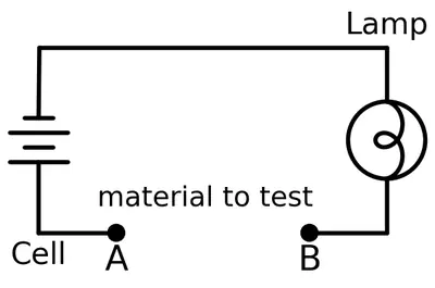
Solution
Step 1 : Recognise what makes the lamp glow
In an electric circuit the lamp glows only when an unbroken conducting path exists from one terminal of the cell, through the lamp-filament, and back to the other terminal. In symbols we say that an electric current $$I$$ will flow only if the circuit is closed by a conductor.
Step 2 : Recall the property of the four test materials shown in Fig. 3.16
| Material placed between A and B | Nature | Expectation |
|---|---|---|
| Iron nail / copper wire | Metal → conductor | Current flows, lamp glows |
| Pencil lead (graphite) | Non-metal but still a conductor | Current flows, lamp glows |
| Aluminium foil | Metal → conductor | Current flows, lamp glows |
| Cardboard strip | Non-metal → insulator | No current, lamp does not glow |
Step 3 : Explain why the cardboard fails to complete the circuit
Cardboard is mainly made of cellulose fibres. These fibres hold their electrons tightly and therefore do not allow free movement of charge carriers. In other words, the electrical resistance $$R$$ of cardboard is extremely high (millions of ohms). Ohm’s law $$I = \dfrac{V}{R}$$ then gives a current so small that the filament of the bulb does not get hot enough to glow.
Conclusion
When the gap AB is bridged with cardboard (or any similar insulating material such as plastic or rubber) the circuit remains open and the lamp stays dark.
Answer
The lamp will not glow when a piece of cardboard (an insulating material) is connected between A and B.
3
Solution
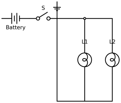
Step 1 : Observe how the two lamps are wired in Fig. 3.17.
- The free end of each filament is joined to the same junction J1, which goes to the positive terminal of the cell.
- The other end of each filament meets at another common junction J2, which returns to the negative terminal.
Because both ends of every lamp are connected to the same pair of junctions, the lamps are in a parallel circuit.
Step 2 : What happens when the filament of one lamp breaks?
- If the filament of lamp 1 breaks, that branch becomes an open circuit; its resistance shoots up to an extremely large value (practically $$\infty$$), so no current flows through that branch.
- The second branch, which contains lamp 2, is still a complete path between J1 and J2. Its filament remains intact, so current can continue to flow through it.
Step 3 : Consequence for the second lamp
Because current can still pass through the unbroken branch, lamp 2 continues to receive energy from the cell and therefore keeps glowing.
Conclusion
In the parallel connection shown in Fig. 3.17, breaking the filament of one lamp does not interrupt the circuit of the other. Hence the other lamp will still glow.
Answer
Yes. The lamps are wired in parallel; breaking one filament only opens that branch, while the other branch still forms a complete path for current, so the second lamp continues to glow.
4 A student forgot to remove the insulator covering from the connecting wires while making a circuit. If the lamp and the cell are working properly, will the lamp glow?
Solution
Given: A simple electric circuit is to be made with a cell (battery), a lamp (bulb) and connecting wires. The metal conducting core of the wires has been left covered with its plastic insulator instead of being exposed at the ends.
To decide: Will the lamp glow or not?
Key facts needed
- For an electric current to flow, every component in the circuit must form a continuous conducting path.
- The metallic core of a connecting wire is a conductor (usually copper or aluminium). The coloured plastic coating is an insulator.
- Insulators do not allow electric charge to pass through them easily.
- A lamp glows only if an electric current passes through its filament.
Step-by-step reasoning
At every joint in the circuit (for example, between the cell terminal and the wire, and between the wire and the lamp terminal) the metal of the wire has to touch the metal of the device. This completes the conducting path.
If the plastic insulation is not removed, the plastic sits between the wire and the device terminal. Plastic is an insulator, so it offers extremely high resistance (effectively an open circuit):
$$R_\text{plastic}\;{\gg}\;10^6\,\Omega$$Because of that very large resistance, the current in the circuit becomes practically zero:
$$I = \dfrac{V}{R_\text{total}} \approx 0\;(\text{ampere})$$With no current through the lamp’s filament, the filament does not get hot and therefore the lamp cannot glow.
Conclusion: Since the insulating plastic prevents the formation of a closed conducting path, the circuit remains open. Hence the lamp will not glow.
Answer
No. The plastic insulation blocks the current, so the circuit stays open and the lamp does not glow.
5

Solution
Step 1 – List the components in a torch
- One dry cell (the electric source)
- One switch (to open or close the circuit)
- One electric bulb (the load)
- Connecting conducting wires
Step 2 – Recall the standard symbols
- Cell : two parallel lines, the longer line marked $$+$$ (positive), the shorter marked $$-$$ (negative)
- Switch : a small break in the line with a movable lever; drawn open when the torch is OFF and closed when it is ON
- Bulb : a circle containing a cross (✖) or filament symbol
- Wires : straight lines joining the symbols
Step 3 – Arrange the symbols in series
- Start at the positive terminal of the cell (long line).
- Draw a straight wire leading to the switch symbol.
- From the other end of the switch draw a wire to the bulb symbol.
- From the opposite side of the bulb draw a wire back to the negative terminal (short line) of the cell, completing the loop.
Step 4 – Label the terminals
Write $$+$$ near the longer plate of the cell and $$-$$ near the shorter plate so that current direction can be traced.
What the finished diagram shows: a single closed loop consisting of cell → switch → bulb → back to cell. When the switch is closed, the bulb glows; when it is open, the circuit breaks and the bulb goes off.
Answer
The circuit diagram of a simple torch consists of one cell, a switch and a bulb connected in series, with the positive ($$+$$) and negative ($$-$$) terminals of the cell clearly marked.
6
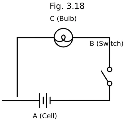
(i) If $$S_2$$ is in 'ON' position, $$S_1$$ is in 'OFF' position, which lamp(s) will glow?
Solution
Step 1 — Understand the wiring shown in Fig. 3.18.
- Each lamp has its own branch that starts from the positive terminal of the battery and returns to the negative terminal.
- Switch $$S_1$$ is placed only in the branch that contains Lamp 1.
- Switch $$S_2$$ is placed only in the branch that contains Lamp 2.
Step 2 — Analyse the position of the switches for this case.
- Given: $$S_2$$ is ON (closed); $$S_1$$ is OFF (open).
- Branch with $$S_2$$ is a complete path, so current flows through Lamp 2.
- Branch with $$S_1$$ is an open path, so no current flows through Lamp 1.
Conclusion: Only Lamp 2 glows, Lamp 1 remains off.
Answer
Lamp 2 (only)
(ii) If $$S_2$$ is in 'OFF' position, $$S_1$$ is in 'ON' position, which lamp(s) will glow?
Solution
Step 1 — Switch positions.
- $$S_2$$ is OFF; its branch is open.
- $$S_1$$ is ON; its branch is closed.
Step 2 — Effect on each lamp.
- Closed branch with $$S_1$$ → current flows → Lamp 1 glows.
- Open branch with $$S_2$$ → current cannot flow → Lamp 2 does not glow.
Conclusion: Only Lamp 1 glows.
Answer
Lamp 1 (only)
(iii) If $$S_1$$ and $$S_2$$ both are in 'ON' position, which lamp(s) will glow?
Solution
Both switches $$S_1$$ and $$S_2$$ are ON.
- Branch 1 (with $$S_1$$ & Lamp 1) is closed → current flows → Lamp 1 glows.
- Branch 2 (with $$S_2$$ & Lamp 2) is also closed → current flows → Lamp 2 glows.
Conclusion: Both lamps glow.
Answer
Both Lamp 1 and Lamp 2
(iv) If both $$S_1$$ and $$S_2$$ are in 'OFF' position, which lamp(s) will glow?
Solution
Both switches $$S_1$$ and $$S_2$$ are OFF.
- Both branches are open, so no closed path exists in the circuit.
- Hence no current can flow through either lamp.
Conclusion: No lamp glows.
Answer
Neither lamp glows
7
Solution
Given information
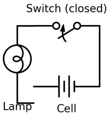
Vidyut has connected a cell (battery), a switch, conducting wires and a lamp exactly as in Fig. 3.19 of the NCERT Class 7 textbook. After the switch is turned ON, the lamp still does not glow.
We must list every possible reason, then describe—step by step—how to find the real cause.
Recall of basic ideas
- An electric lamp glows only when an unbroken conducting path (closed circuit) exists and when the cell can provide a potential difference large enough to push current through the filament.
- Current $$I$$ in a simple circuit is given by Ohm’s law $$I = \dfrac{V}{R}$$, where $$V$$ is the cell voltage and $$R$$ is the total resistance. If $$V = 0$$ (a dead cell) or if $$R \to \infty$$ (open circuit, broken filament, loose connection), then $$I = 0$$ and the lamp remains dark.
Part A Possible reasons for the lamp not glowing
- Dead cell / discharged battery. The cell may be exhausted, giving almost $$V = 0\;\text{V}$$.
- Cell connected the wrong way or in reverse. A single bulb normally still glows, but if two or more cells are incorrectly arranged, their voltages can cancel.
- Insulating cover on the cell terminals. Sometimes a thin plastic disc is left on a new dry cell; it prevents contact.
- Switch left open (OFF) or internally broken.
- Loose connection at any screw, crocodile clip or binding post.
- Broken connecting wire. The copper core may have snapped inside the plastic cover.
- Corrosion on terminals or clips. An oxide layer behaves like an insulator $$R \approx \infty$$.
- Bulb fused (filament broken). An open filament also means $$R \approx \infty$$.
- Bulb holder faulty. The central foot contact or the side contact may not touch the bulb base firmly.
- Excessive resistance in the circuit (too thin or too long a wire). Current $$I$$ becomes too small to heat the filament to incandescence.
- Short circuit bypassing the lamp. If the two wires touching the lamp terminals accidentally touch each other, current misses the lamp completely.
Part B Step-by-step test plan to locate the fault
- Visual inspection
• Look for any obvious breaks, loose ends, or bare wires touching.
• Check that the switch lever actually touches the other terminal when in the ON position.
• Examine the bulb to see whether the thin tungsten filament inside is intact. - Check the cell
• Touch its two terminals momentarily with the tongue (not recommended in school) or better
• Connect a voltmeter; if $$V \lt 1\;\text{V}$$ for a 1.5 V cell, the cell is probably dead.
• Alternatively, connect the cell directly to a known-good torch bulb; if it does not glow at all, replace or recharge the cell. - Test the bulb separately
• Remove the bulb and connect it straight across the same cell with two short wires.
• If it fails to light, the filament is broken or the bulb rating is too high for the cell voltage. - Check continuity of wires and switch
• Use a continuity tester or multimeter set to the lowest resistance range.
• One by one, test each wire, then the switch when ON. The meter should read almost $$0\;\Omega$$. A reading $$R \to \infty$$ shows an open circuit. - Clean and tighten all connections
• Scrape oxide layers gently with sand-paper.
• Tighten screws/clips so that shiny metal touches shiny metal. Good contact keeps $$R$$ small. - Reassemble and re-test the whole circuit
• Close the switch again. If the lamp now glows, the fault has been removed.
• If not, repeat steps 2 to 5 until the defective part is finally identified and replaced.
Summary
The lamp fails to glow whenever no current or an insufficient current flows. This may be due to a defect in the cell, bulb, switch, wires, contacts, or the way parts are connected. A systematic isolation test—checking one component at a time—quickly reveals the exact reason.
Answer
The lamp may be dark because of any of these faults:
- dead or wrongly connected cell
- plastic cap left on cell terminal
- switch open or broken
- loose / corroded contacts
- broken connecting wire
- short circuit bypassing lamp
- fused bulb or faulty holder
- too much resistance in the leads
To locate the trouble: (i) look for visible breaks, (ii) test the cell with a voltmeter or a known bulb, (iii) test the bulb on a fresh cell, (iv) check continuity of every wire and the switch, (v) clean & tighten all joints, then re-assemble and try again.
8
Solution
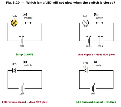
Observing the four circuits shown in Fig. 3.20
- Case (i) – both leads coming from the same terminal of the cell.
Current has no return path to the other terminal, therefore the circuit is open and no current can flow. - Case (ii) – the connection touches only the glass/plastic part of the bulb/LED at one side.
That point is an insulator; hence the circuit again remains open and no current flows. - Case (iii) – both leads are joined to the same metallic terminal of the lamp/LED (either both on the cap or both on the side).
The two terminals of the source are not linked through the filament/LED chip, so the circuit is incomplete. - Case (iv) – one lead goes to the cap (or longer anode leg of the LED) and the other to the side terminal (or shorter cathode leg) and each lead reaches a different cell terminal.
There is now a continuous conducting path from one terminal of the cell, through the switch, through the filament/LED, and back to the other terminal. Current flows and the lamp/LED glows.
Thus the lamp/LED fails to glow in all the arrangements except the fourth one.
Answer
The lamp/LED will not glow in cases (i), (ii) and (iii); it glows only in case (iv).
9 Suppose the '+' and '-' symbols cannot be read on a battery. Suggest a method to identify the two terminals of this battery.
Solution
Objective: To find out which end of an unmarked battery is positive ($$+$$) and which is negative ($$-$$).
Scientific fact used: A light-emitting diode (LED) conducts electric current in only one direction. The LED glows when its anode (the longer lead) is connected to the higher potential and its cathode (the shorter lead, often next to a flat edge on the plastic body) is connected to the lower potential.
If $$V_\mathrm{anode}$$ and $$V_\mathrm{cathode}$$ denote the potentials at the two leads, the LED behaves as follows:
\[ I = 0 \quad \text{when} \quad V_\mathrm{anode} - V_\mathrm{cathode} \lt V_f \] \[ I \gt 0 \;\; (\text{LED glows}) \quad \text{when} \quad V_\mathrm{anode} - V_\mathrm{cathode} \ge V_f \]Here $$V_f$$ is the forward-bias voltage of the LED. For a common red LED, $$V_f \approx 1.8\text{–}2.0\,\mathrm{V}$$ (green, blue and white LEDs need even more), so a 3 V battery (or two 1.5 V cells in series) is needed to light it.
Apparatus required
- One LED (a red LED, which needs about $$2\,\mathrm{V}$$ to glow).
- One $$220\,\Omega$$–$$470\,\Omega$$ resistor used as a current limiter.
- Two short pieces of insulated copper wire with bare ends.
- The unmarked battery whose terminals are to be identified (use a 3 V battery, or two 1.5 V cells in series, so the LED's forward voltage is comfortably exceeded).
Step-by-step procedure
- Identify the longer lead of the LED; this is its anode. The shorter lead is the cathode.
- Twist (or solder) the resistor in series with either lead of the LED. The resistor keeps the current small enough that the LED is not damaged.
- Connect one piece of wire to the free end of the resistor and another piece of wire to the remaining lead of the LED.
- Touch the two free wire ends to the two unknown terminals of the battery. Note which terminal is touched by the wire coming from the anode (long-lead) side.
- Observation
- If the LED glows, current is flowing from anode to cathode through the LED. Therefore the terminal touched by the anode-side wire is the positive (+) terminal, and the other terminal is the negative (–) terminal.
- If the LED does not glow, swap the two wires at the battery. The LED should now light up. The terminal that is now in contact with the anode-side wire is the positive (+) terminal, and the other one is the negative (–) terminal.
Result: The terminal that allows the LED to glow when joined to its longer lead (anode) is the positive terminal of the battery; the other terminal is the negative one.
Note: Any one-way (polarity-sensitive) device—a silicon diode in series with a bulb, an analogue galvanometer, or a digital multimeter set on the d.c. voltage range—could be used instead of the LED, but the LED is the quickest and safest option for a school laboratory.
Answer
Connect an LED in series with a small ($$\approx 220\,\Omega$$) resistor across the two unknown terminals (use a 3 V battery because a red LED needs about $$2\,\mathrm{V}$$ to glow). If the LED lights up, the terminal joined to the LED's longer lead (anode) is the positive (+) terminal and the other is negative (–). If it does not glow, swap the connections; once the LED lights up, the terminal now touching the longer lead is positive.
10 You are given six cells marked A, B, C, D, E, and F. Some of these are working and some are not. Design an activity to identify which of them are working.
(i) List the items that you require.
Solution
Items required
- Six given cells labelled A, B, C, D, E and F
- One small torch bulb (1.5 V or 2 V)
- One bulb holder (optional but convenient)
- Two pieces of insulated copper connecting wire (about 15 cm each) with bare ends
- A switch or a simple key (you may use a crocodile clip or just touch the wire ends manually)
Answer
Cells A–F, torch bulb, 2 connecting wires, and a switch/bulb-holder.
(ii) Write the procedure that you will follow.
Solution
Step-by-step procedure
- Make a simple test circuit:
• Fix the bulb in the holder.
• Connect one terminal of the bulb holder to one end of the switch with a wire.
• Connect the free terminal of the switch to a loose free wire end. This loose end will later touch the negative terminal of the cell under test.
• Attach a second wire to the remaining terminal of the bulb holder; keep its other end loose to touch the positive terminal of the cell. - Close the key to check that the bulb filament is intact (it should not glow because no cell is yet connected).
- Test each cell one by one:
• Hold the cell so that its metal cap is the positive (+) terminal and its flat base is the negative (–) terminal.
• Touch the loose wire from the switch to the flat base (–).
• Simultaneously touch the loose wire from the bulb holder to the metal cap (+).
• Observe the bulb. - If the bulb glows brightly, the cell is working. If the bulb does not glow at all or glows only very dimly, the cell is weak or dead.
- Mark the result for the cell tested and repeat the same steps for every other cell.
Safety note: test each cell for only a few seconds so that the cell and bulb do not get warm.
Answer
Connect a bulb and switch in series, touch the bulb-wire to the cell’s + terminal and the switch-wire to its – terminal; a glowing bulb means the cell works, no glow means it does not. Test all six cells one after another and record the observation.
(iii) With the items, carry out the activity to identify the cells that are working.
Solution
Apparatus arranged on the table
- The six cells A, B, C, D, E and F lined up in front of you.
- One small torch bulb ($$1.5\,\mathrm{V}$$ or $$2\,\mathrm{V}$$) fixed in a bulb holder.
- A simple ON/OFF switch (or a key).
- Two pieces of insulated copper wire (about 15 cm long) with the plastic stripped off at both ends.
Wiring up the test circuit (do this once, before testing any cell)
- Screw the torch bulb into the bulb holder.
- Take wire 1: connect one stripped end to a terminal of the bulb holder, and connect the other stripped end to one terminal of the switch.
- Take wire 2: connect one stripped end to the remaining terminal of the bulb holder; the other stripped end is left free — call it the probe P.
- Attach one more short wire (or use a long bare end) to the free terminal of the switch; this free end will act as the probe Q.
- Make sure the switch is in the OFF position so the bulb stays dark when no cell is in the loop.
Now we have an open circuit: bulb holder → switch → probe Q on one side and bulb holder → probe P on the other side. Touching the two probes to a cell’s terminals will close the loop.
Testing each cell
- Pick up cell A. The metal cap is the positive (+) terminal and the flat zinc base is the negative (–) terminal.
- Press probe P firmly on the cap (+) and probe Q on the base (–).
- Push the switch to ON for a few seconds and watch the bulb. Then switch OFF and remove the probes.
- Record whether the bulb glowed brightly, dimly or not at all.
- Repeat the same procedure for cells B, C, D, E and F, one after another.
Test each cell for only a few seconds so the cell, wires and bulb do not get warm.
Observations
| Cell | Bulb glows? | Conclusion |
|---|---|---|
| A | Yes (bright) | Working |
| B | No | Not working |
| C | Yes (bright) | Working |
| D | No | Not working |
| E | Yes (bright) | Working |
| F | No | Not working |
Result
Cells A, C and E light the bulb and are therefore the working cells. Cells B, D and F do not light the bulb, so they are exhausted or faulty and cannot be used.
Answer
Wire the bulb, switch and two leads in series so two free probe ends are left out of the loop. Press the probes to the (+) cap and (–) base of each cell in turn and close the switch for a few seconds. The bulb glows brightly for cells A, C and E, so they are the working cells; it does not glow for cells B, D and F, so these are not working.
11
Solution
Step 1 – Requirement of the LED
An ordinary LED needs about $$V_{\min}\approx2\,\text{V}$$. Two dry cells in series give $$1.5\,\text{V}+1.5\,\text{V}=3\,\text{V}$$, which is sufficient.
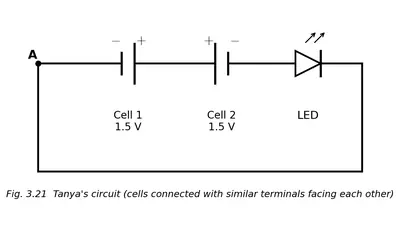
Step 2 – What is wrong in Fig. 3.21?
In the figure both cells are joined positive-to-positive and negative-to-negative. That is a parallel connection, so the available potential difference is only
$$V=V_1=1.5\,\text{V} Hence the LED cannot glow. Step 3 – Correct connection of the cells Now the total voltage is $$V=V_1+V_2=3\,\text{V}\ge V_{\min}$$, so the LED will glow. Diagram to draw: Two cells end-to-end (series), their touching terminals linked by a short wire. From the free positive terminal run a wire to the LED’s anode. The LED’s cathode goes to a switch, and the switch returns to the free negative terminal of the second cell, completing the circuit.
Answer
No. The cells are in parallel, giving only 1.5 V. Connect them in series (positive of one to negative of the other) and complete the circuit through the LED and the switch; then the LED will glow.
Exploratory Projects
1 Suppose that due to some problem, the power supply is disrupted in your area for two days. List out which actions from your daily life you would not be able to do.
Solution
Understanding the situation
In our homes and in the locality almost every activity that feels “normal” relies, directly or indirectly, on the continuous flow of electric current. When the supply fails for two complete days, every device that needs electricity stops working. Below is a careful, point-by-point discussion of each such activity. The aim is to make you consciously connect the action with the electrical component that makes it possible.
- Lighting and visibility
• No tube-lights, LED bulbs, CFLs or night-lamps will glow.
• You would have to depend on candles, kerosene lamps or battery torches for illumination at night. - Cooling and ventilation
• Ceiling fans, table fans and exhaust fans stop.
• Air-conditioners and coolers cannot run, leading to an uncomfortably hot and stagnant room, especially in summer. - Heating appliances
• Electric geysers, immersion rods and room-heaters remain off, so you cannot get instant hot water for bathing or washing dishes, nor can you warm the room in winter. - Food-related work
• Refrigerators turn off — ice melts and food may spoil.
• Electric mixers, grinders, microwave ovens, induction cook-tops, toasters and rice-cookers all become useless.
• The kitchen chimney and exhaust fan also stop. - Cleaning and washing
• Electric water-pump (if your building uses one) will not lift water to overhead tanks; tap water supply inside flats may stop.
• Washing machines, dryers and vacuum cleaners do not work.
• Electric irons cannot be used to press clothes. - Entertainment and information
• Televisions, radios (unless battery-operated), set-top boxes, DVD players and music systems remain silent.
• Computers, laptops (after the battery discharges) and gaming consoles cannot be used.
• Internet routers shut down, so Wi-Fi is lost even if your phone still has some battery. - Communication
• Mobile-phone chargers, cordless-phone base units and land-line modems stop; once the battery of a phone is drained you cannot call or message. - Study and office work
• No electric light to read under after sunset.
• Printers, scanners and desktop PCs cannot be switched on. - Water and sanitation
• Electric water purifiers (RO systems) and UV filters are off.
• Motor-driven flush systems in some modern toilets stop working. - Transportation aids
• Lifts (elevators) in multi-storey buildings and escalators in malls or metro stations do not run.
• Electric vehicle-charging points cannot charge e-bikes or e-scooters. - Safety and security
• CCTV cameras, electronic doorbells, automatic gates and alarm systems are disabled unless they have independent battery backups.
• Street-lights in many areas go dark, reducing night-time safety. - Medical and health-care devices at home
• Nebulisers, digital thermometers (rechargeable types), electric heating pads or blankets and health-monitoring devices (BP machine, glucometer chargers) cannot be used once their internal batteries discharge. - Miscellaneous small gadgets
• Hair-dryers, electric shavers or trimmers, electric toothbrush chargers, mosquito repellant vapourisers and aroma diffusers all stop.
Conclusion
A two-day power cut affects practically every sphere of daily life — comfort, food, hygiene, communication, entertainment, safety and even health. The situation highlights our heavy dependence on electricity and the importance of having backup solutions such as batteries, inverters or generators for essential needs.
Answer
Without electricity for two days you would be unable to
• light your home at night,
• run fans, coolers or air-conditioners,
• use heaters or geysers,
• keep food fresh in the refrigerator or use microwave/induction cook-tops,
• pump water, operate washing machines or irons,
• watch TV, use a computer, router or charge mobile phones,
• ride lifts, use electric bells, security cameras or street-lights,
• and operate any other household gadget that needs mains power.
2
Solution
Required components
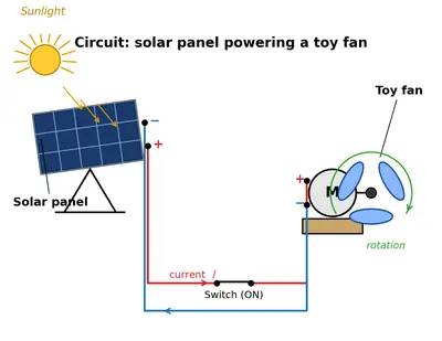
- One small solar panel (Fig. 3.22a)
- Two or three short pieces of insulated connecting wire with crocodile clips
- One simple key / switch
- One toy fan fitted with a d.c. motor (Fig. 3.22b)
1. Identify the terminals
- The solar panel has two fixed leads marked + (red) and − (black).
- The motor of the toy fan has two solder-lugs that act as its + and − terminals.
2. Plan the closed path for current
Solar + → Key → Motor + → Motor coil → Motor − → Solar −.
3. Actual connections
- Clip one wire between the + terminal of the solar panel and one screw of the key.
- Clip a second wire from the other screw of the key to the + terminal of the motor.
- Clip a third wire from the − terminal of the motor back to the − terminal of the solar panel. The circuit is now complete but open at the key.
4. Testing
- Keep the key open → no current, the fan stays still.
- Place the panel in bright sunlight and press (close) the key → current $$I$$ flows; electrical energy from the panel is converted by the motor into mechanical energy, so the fan blades rotate.
5. Circuit diagram to draw
- Rectangle labelled “Solar panel” with terminals + and −.
- From +: straight line to the symbol of an open key.
- From the other side of the key: line to the symbol of a d.c. motor (circle with M or miniature fan).
- Return line from the second motor terminal to the − terminal of the panel, completing a loop.
- Arrow showing conventional current direction $$I$$ from the panel’s + back to its −.
Closing the key produces the arrangement shown in Fig. 3.22c and the toy fan runs solely on solar power.
Answer
Connect Solar + → Switch → Fan + and Fan − → Solar −; when the switch is closed in sunlight the circuit is complete and the toy fan rotates.
3 Visit an electrical items shop. With the help of the shopkeeper, identify the various types of cells available. For each cell, also find out which device(s) it is used for. Prepare a report.
Solution
Objective of the visit
Prepare a report for Chapter 3 (Electricity) by identifying as many different kinds of electric cells as an ordinary electrical-items shop keeps and find out at least one device in which each cell is normally used.
Planning before the visit
- Carry a notebook, pen, and a mobile phone for photographs (taken only after obtaining the shopkeeper’s permission).
- Prepare the following questions for the shopkeeper.
- What is the name of the cell?
- Is it primary (single-use) or secondary (rechargeable)?
- What is its standard voltage $$V$$ (nominal)?
- Which everyday device generally needs it?
- Recall the symbol for a cell $$\bigl(\text{one long line and one short line}\bigr)$$ so that you can recognise packaged primary cells easily.
Observation table prepared in the shop
| Sl. No. | Common name of the cell | Chemical type* | Primary / Secondary | Nominal voltage $$V$$ | Physical shape & size | Usual device(s) |
|---|---|---|---|---|---|---|
| 1 | AA (pen-torch) dry cell | Zinc–Carbon | Primary | $$1.5\,\text{V}$$ | Cylinder ≈ 50 mm × 14 mm | TV remote, toys, wall-clock |
| 2 | AAA dry cell | Zinc–Carbon or Alkaline | Primary | $$1.5\,\text{V}$$ | Smaller cylinder ≈ 44 mm × 10.5 mm | Smaller remotes, trimmers, glucose meter |
| 3 | 9-volt transistor battery | Six tiny $$1.5\,\text{V}$$ cells in series | Primary | $$9\,\text{V}$$ | Rectangular block ≈ 26 × 17 × 48 mm | Multimeter, cordless microphone, smoke alarm |
| 4 | Button cell (e.g. LR44) | Alkaline / Silver oxide | Primary | $$1.5\,\text{V}$$ | Flat metal disc Ø ≈ 11.6 mm | Wrist watch, pocket calculator, laser pointer |
| 5 | Coin cell (CR2032) | Lithium-manganese | Primary | $$3\,\text{V}$$ | Disc Ø ≈ 20 mm, thickness ≈ 3.2 mm | Computer CMOS backup, weighing scale, car key |
| 6 | NiMH rechargeable AA | Nickel–Metal Hydride | Secondary | $$1.2\,\text{V}$$ | Same as AA | Digital camera, wireless mouse, hobby robots |
| 7 | Mobile-phone Li-ion cell | Lithium-ion polymer | Secondary | ≈ $$3.7\,\text{V}$$ (nominal) up to $$4.2\,\text{V}$$ (fully charged) | Flat rectangular pouch | Smartphones, power banks (several in parallel) |
| 8 | Lead–acid battery (mini-UPS type) | Lead–acid | Secondary | $$12\,\text{V}$$ (6 cells × 2 V each) | Sealed block ≈ 15 × 9 × 10 cm | Emergency light, computer UPS, small inverter |
| 9 | Solar cell (single photovoltaic cell) | Silicon p–n junction | Energy source, not storage | ≈ $$0.5$$ to $$0.6\,\text{V}$$ per cell | Flat square ~ 10 cm × 10 cm | Solar garden lamp (with NiMH backup battery) |
*Chemical type is mentioned exactly as it appeared on the packet or as told by the shopkeeper.
Key learning points explained to the shopkeeper and noted in the report
- A primary cell is meant for single use. Its chemical reaction is not designed to be reversed. Example: the zinc–carbon AA cell.
- A secondary cell is rechargeable because its reaction can run both forward and backward. Example: the lead–acid or Li-ion cell.
- When several $$1.5\,\text{V}$$ cells are connected in series, the net emf becomes the sum:
$$V_{\text{total}} = n \times 1.5\,\text{V}$$ where $$n$$ is the number of cells. - Different shapes (cylindrical, disc, pouch) make it easy for manufacturers to prevent wrong insertion and to fit into the allotted space inside a device.
Safety advice given by the shopkeeper
- Do not throw cells into fire; they can burst.
- Always match charger type with battery chemistry; e.g. never charge a zinc–carbon cell in a NiMH charger.
- Recycle depleted button and coin cells because they contain heavy metals.
Conclusion
The shop stocked nine clearly different types of cells. Their voltages ranged from about $$0.5\,\text{V}$$ (single solar cell) to $$12\,\text{V}$$ (sealed lead–acid unit). Each type is optimised for a particular set of devices. The variety shows that no single cell can satisfy every requirement — long life, high current, small size, rechargeability, or low cost — at the same time.
Answer
Nine distinct cells were identified: AA, AAA, 9-V battery, LR44 button, CR2032 coin, NiMH AA, Li-ion mobile pack, 12-V lead–acid block and a single photovoltaic solar cell. Their usual devices are, respectively, TV remotes / toys, slim remotes / trimmers, multimeters, wrist-watches, CMOS memory, digital cameras, smartphones, UPS-lights and solar garden lamps. Thus the report meets the textbook requirement.
4 Prepare a list of objects in your home under three categories:
(i) Objects which are electrical insulators only
Solution
Step 1 – Recall the idea of an electrical insulator
An electrical insulator is a material through which electric current does not flow easily. In symbols we can say that for an ideal insulator the current is practically zero, $$I \approx 0\;\text{A}$$ even if a potential difference is applied.
Step 2 – Look around the house for articles made wholly of insulating materials
Typical insulating substances are plastic, rubber, dry wood, glass, porcelain/ceramic, Styrofoam, wool, paper. Anything made entirely of one of these can safely be placed in this category.
Step 3 – Final list for the answer
- Plastic comb
- Rubber slipper/flip-flop
- Dry wooden chopping board
- Glass flower vase
- Ceramic coffee mug
- Styrofoam (thermocol) disposable plate
- Woollen blanket
- Polythene carry bag
Each of the above articles is made only of insulating material, therefore they fall under category (i).
Answer
Examples: plastic comb, rubber slippers, dry wooden chopping board, glass vase, ceramic mug, Styrofoam plate, woollen blanket, polythene bag.
(ii) Objects which are electrical conductors only
Solution
Step 1 – Recall the idea of an electrical conductor
A conductor lets electric charge move freely through it. When a potential difference is applied, a measurable current flows, $$I \neq 0\;\text{A}$$. All common metals and the graphite form of carbon are good conductors.
Step 2 – Search for items made entirely of conducting material
Look for objects that are all metal (or all graphite) and have no insulating handles or covers.
Step 3 – Final list for the answer
- Stainless-steel spoon
- Aluminium pressure-cooker lid (excluding the plastic handle)
- Pure copper wire (bare, without plastic covering)
- Brass house-key
- Iron nail
- Metal water tap/spout
- Graphite pencil-lead taken out of the wooden body
These objects are made solely of conducting material, so they belong to category (ii).
Answer
Examples: stainless-steel spoon, aluminium cooker lid (metal part), bare copper wire, brass key, iron nail, metal water tap, graphite pencil-lead.
(iii) Objects which are made of both, whose some parts are insulators and some electrical conductors
Solution
Step 1 – Mixed objects
Many household appliances and tools are deliberately built with both parts: a metallic part to carry current or heat (conductor) and a plastic/rubber/wooden part for safe handling (insulator).
Step 2 – Prepare the list
| Object | Conducting part(s) | Insulating part(s) |
|---|---|---|
| Electric iron | Iron/steel sole-plate, internal copper wires | Plastic handle, rubber power-cord covering |
| Saucepan with plastic handle | Aluminium/stainless body | Plastic or bakelite handle |
| Mobile-phone charger plug | Metal pins | Plastic outer casing |
| Screwdriver | Steel blade | Plastic grip |
| Table lamp | Metal stand and bulb holder | Plastic switch knob, PVC wire insulation |
| Electric kettle | Stainless-steel heating vessel | Plastic lid and handle |
| Mixer-grinder | Copper motor windings, steel jar blades | Plastic body and jar lid |
Because each article contains both types of material, they fit category (iii).
Answer
Examples: electric iron, saucepan with plastic handle, mobile-phone charger plug, screwdriver, table lamp, electric kettle, mixer-grinder (each has metal conducting parts and plastic/rubber insulating parts).


