Join WhatsApp Icon JEE WhatsApp Group
NCERT Solutions for Class 6 Maths

Chapter 2: Lines and Angles

Download Solutions PDF
Daily JEE Updates, Tips & Important Alerts
Join 30,000+ students and stay updated with JEE notifications and preparation insights.
Join Now!
Free PDF
Complete NCERT Solution PDF for Chapter 2: Lines and Angles

NCERT Solutions For Class 6 Mathematics Chapter 2 Lines and Angles helps students understand the basics of geometry, including different types of lines, angles, and their properties. The page offers NCERT Solutions that explain every concept from the chapter in a clear and structured way. NCERT Solutions For Class 6 Maths help students learn about line segments, rays, angles, and measuring angles using simple examples. The chapter builds essential geometry skills that are required for higher-level mathematical learning. Students can use these solutions to solve textbook questions, revise concepts, and improve accuracy in problem-solving. A PDF version of the chapter solutions is also available for easy access during preparation. The explanations help students develop confidence in understanding geometric figures and their properties.

Download Solutions PDF

Exercise 2.4 

Question 1.Rihan marked a point on a piece of paper. How many lines can he draw that pass through the point?

Sheetal marked two points on a piece of paper. How many different lines can she draw that pass through both of the points?

Can you help Rihan and Sheetal find their answers?

Solution

Concepts we need

  • A point shows only a position; it has no length or width.
  • A line is straight, has no ends on either side (it extends without limit) and is completely fixed as soon as we know any two of its points.

(A) Lines through one point (Rihan’s case)

• Suppose Rihan places his pencil tip on the single point $$P$$.
• He can now tilt the ruler in any direction he likes and draw a straight line.
• There is no restriction on how much he turns the ruler, so he can choose endlessly many directions.

The number of possible directions around the point is unlimited, so the count of different lines is unlimited.

\[ \text{Lines through one point }= \text{infinitely many} \]

(B) Lines through two distinct points (Sheetal’s case)

• Let the two points be $$A$$ and $$B$$, and assume they are not the same point (they are distinct).
• Place the ruler so that its edge passes exactly through both $$A$$ and $$B$$. A straight trace of that edge is one line.
• Try to move the ruler while still keeping both points under the edge—it cannot be done unless the ruler stays exactly where it was, because any small turn will leave either $$A$$ or $$B$$.

Therefore, only one straight line can pass through the same two points.

\[ \text{Lines through two distinct points }=1 \]

Final answers

  • Rihan can draw infinitely many different lines through his single point.
  • Sheetal can draw exactly one line through her two points.

Answer

Rihan: infinitely many lines.
Sheetal: exactly one line.

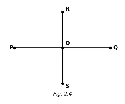
Question 2.Name the line segments in Fig. 2.4. Which of the five marked points are on exactly one of the line segments? Which are on two of the line segments?

Fig. 2.4
Fig. 2.4

Solution

Step 1 — Identify the straight pieces in the drawing
In Fig. 2.4 two straight pieces are visible:

  • one joins the end–points A and B,
  • the other joins the end–points C and D.

Each straight piece that has two fixed end–points is called a line segment. Hence the two line segments present are

$$\overline{AB} \quad\text{and}\quad \overline{CD}.$$

Step 2 — Locate the five marked points
The figure shows five labelled points:

  • A and B lie only on $$\overline{AB},$$
  • C and D lie only on $$\overline{CD},$$
  • O is the common point where $$\overline{AB}$$ and $$\overline{CD}$$ cross each other.

Step 3 — Classify the points

Points lying on exactly one line segmentPoint lying on two line segments
A, B, C, DO

Answer

Line segments : $$\overline{AB},\;\overline{CD}$$
Points on exactly one of them : A, B, C, D
Point on both of them : O

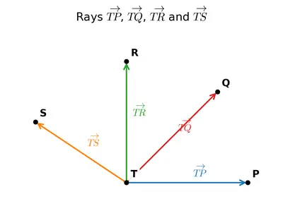
Question 3.Name the rays shown in Fig. 2.5. Is T the starting point of each of these rays?

Fig. 2.5
Fig. 2.5

Solution

Step 1 : Recall the definition of a ray
A ray is a part of a line that starts from one point (called its initial point) and extends endlessly in one direction. We name a ray by writing
its initial point first, followed by any other point that lies on the ray. For example, a ray that starts from A and passes through B is written as $$\overrightarrow{AB}$$.

Step 2 : Read the letters that appear on each arrow in Fig. 2 .5
The picture shows four arrows coming out of the point T and passing through the points P, Q, R and S respectively (only the heads of the arrows are drawn at P, Q, R and S). Therefore the four rays are

  • the ray that starts from T and passes through P  ⇒  $$\overrightarrow{TP}$$,
  • the ray that starts from T and passes through Q  ⇒  $$\overrightarrow{TQ}$$,
  • the ray that starts from T and passes through R  ⇒  $$\overrightarrow{TR}$$,
  • the ray that starts from T and passes through S  ⇒  $$\overrightarrow{TS}$$.

Step 3 : Decide whether T is the starting point of every ray
In each of the four names written above the first letter is T. Hence, T is indeed the initial point of every one of the rays shown in the figure.

Conclusion
The rays are $$\overrightarrow{TP}, \overrightarrow{TQ}, \overrightarrow{TR} \text{ and } \overrightarrow{TS}$$, and T is the starting point of each of them.

Answer

The rays are $$\overrightarrow{TP},\;\overrightarrow{TQ},\;\overrightarrow{TR},\;\overrightarrow{TS}$$.
Yes, in every case T is the starting point of the ray.

Question 4. Draw a rough figure and write labels appropriately to illustrate each of the following:

a $$\overleftrightarrow{OP}$$ and $$\overleftrightarrow{OQ}$$ meet at O.

Solution

Step 1 – Mark a point O roughly in the middle of your page.

Step 2 – Through O draw one straight line and extend it well on both sides. Choose one point on the left part of the line and write the letter P. Choose one point on the right part of the same line and write the letter P’ (or leave it unlabeled—only the arrow heads are necessary).

Step 3 – Place arrow heads at the two ends of this straight line to show that it continues without end in both directions. This is the required line $$\overleftrightarrow{OP}$$.

Step 4 – Through the same point O draw another straight line that is not parallel to the first one, so that it actually intersects the first line only at O. Again extend this new line on both sides of O and put arrow heads. Mark one point on it and name it Q. (If you like, you may put a point and call it Q on one side and a point called Q’ on the opposite side.) This new line is $$\overleftrightarrow{OQ}$$.

You now have two intersecting lines $$\overleftrightarrow{OP}$$ and $$\overleftrightarrow{OQ}$$ meeting at the common point O, exactly as asked.

Answer

Two straight lines, $$\overleftrightarrow{OP}$$ and $$\overleftrightarrow{OQ}$$, are drawn through the same point O so that they intersect only at O.

b $$\overleftrightarrow{XY}$$ and $$\overleftrightarrow{PQ}$$ intersect at point M.

Solution

Step 1 – Mark point M on your sheet.

Step 2 – Through M draw a straight line and extend it well in both directions. Put arrow heads at both ends to show that it is a line. On one side of M choose a point on the line and mark it X; on the opposite side mark it Y. The whole line is therefore $$\overleftrightarrow{XY}$$, and the chosen point M lies on it.

Step 3 – Now draw another straight line through the same point M but slanting so that it is not the same as the first line. Extend it indefinitely in both directions and put arrow heads. Choose and mark one point on this second line as P and another as Q, one on each side of M. This second line is $$\overleftrightarrow{PQ}$$.

Thus two lines $$\overleftrightarrow{XY}$$ and $$\overleftrightarrow{PQ}$$ intersect exactly at one common point M, as required.

Answer

Two intersecting lines $$\overleftrightarrow{XY}$$ and $$\overleftrightarrow{PQ}$$ are drawn so that their only common point is M.

c Line $$l$$ contains points E and F but not point D.

Solution

Step 1 – Draw a straight line and extend it amply on both sides; place arrow heads to indicate that it goes on forever. Label this line with the small letter l.

Step 2 – Choose any two distinct points on this line and label them E and F. Since the points actually lie on line l, we say “E and F belong to l” or “E, F ∈ l.”

Step 3 – Now choose a third point, labelled D, clearly off the line l (that is, position D somewhere not touching the drawn line). State explicitly: “Point D does not lie on l.”

The completed sketch therefore shows: line l; points E and F on that line; point D away from that line.

Answer

On line l, points E and F are marked; point D is shown outside the line, so D ∉ l.

d Point P lies on AB.

Solution

Step 1 – Draw a straight line segment and label its end–points A and B. (Put no arrow heads because only the segment AB is needed here, not the whole line.)

Step 2 – Choose any point between A and B on this segment and mark it P.

Because P is marked directly on segment AB, we write: “Point P lies on AB.”

Answer

The point P is shown on the segment AB, i.e. P lies on AB.

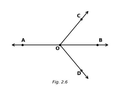
Question 5. In Fig. 2.6, name:

Fig. 2.6
Fig. 2.6

a Five points

Solution

From the diagram given in Fig. 2.6 we simply have to read off any five different labels that mark points.
A systematic way is to start at the top of the figure and move clockwise (or anticlockwise) noting each label once. Doing so we meet the points
$$A,\;B,\;C,\;D\text{ and }E.$$
Thus, the required five points are

  • $$A$$
  • $$B$$
  • $$C$$
  • $$D$$
  • $$E$$

Answer

$$A,\;B,\;C,\;D,\;E$$

b A line

Solution

In the figure the straight path that passes through the two extreme points $$A$$ and $$B$$ is an infinitely long straight line. We name it by any two points lying on it, so the line is

$$\overleftrightarrow{AB}.$$

Answer

$$\overleftrightarrow{AB}$$

c Four rays

Solution

A ray starts at an initial point and extends without end in one direction. In Fig. 2.6 four such rays start from the common end point $$B$$ and pass through the other four points. Listing them with their starting point first we get

  • $$\overrightarrow{BA}$$
  • $$\overrightarrow{BC}$$
  • $$\overrightarrow{BD}$$
  • $$\overrightarrow{BE}$$

Answer

$$\overrightarrow{BA},\;\overrightarrow{BC},\;\overrightarrow{BD},\;\overrightarrow{BE}$$

d Five line segments

Solution

A line segment joins two chosen points and has both end points fixed. Picking every possible pair that can be joined in the diagram and then selecting any five of them we may list

  • $$\overline{AB}$$
  • $$\overline{BC}$$
  • $$\overline{BD}$$
  • $$\overline{BE}$$
  • $$\overline{CD}$$

(Any other valid set of five distinct segments found in the figure would also score full marks.)

Answer

$$\overline{AB},\;\overline{BC},\;\overline{BD},\;\overline{BE},\;\overline{CD}$$

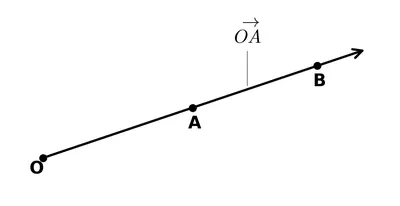
Question 6.Here is a ray $$\overrightarrow{OA}$$ (Fig. 2.7). It starts at O and passes through the point A. It also passes through the point B.

Fig. 2.7
Fig. 2.7

a Can you also name it as $$\overrightarrow{OB}$$? Why?

Solution

A ray is named by writing

  • the end-point first, and
  • any one point lying on the ray next.

In the given figure the end-point is $$O$$ and the ray passes through two points $$A$$ and $$B$$ that both lie on the same side of $$O$$.

Therefore, besides naming the ray as $$\overrightarrow{OA}$$ (using point $$A$$), we may equally well use the other point $$B$$ that lies on the same path. Putting the end-point $$O$$ first and point $$B$$ next we get

$$\overrightarrow{OB}$$.

Hence the same ray can indeed be written as $$\overrightarrow{OB}$$ because $$B$$ is also a point on that ray.

Answer

Yes. Since $$O$$ is the end-point and $$B$$ lies on the same ray, we may name it $$\overrightarrow{OB}$$.

b Can we write $$\overrightarrow{OA}$$ as $$\overrightarrow{AO}$$? Why or why not?

Solution

To name a ray we must write the end-point first. If we write $$\overrightarrow{AO}$$, the first letter is $$A$$, so $$A$$ would be treated as the end-point and the ray would start at $$A$$ and pass through $$O$$. That is a different ray—it goes in the opposite direction.

Because the true end-point here is $$O$$ (not $$A$$), the correct name must start with $$O$$. Hence

$$\overrightarrow{OA} \neq \overrightarrow{AO}$$.

So we cannot write $$\overrightarrow{OA}$$ as $$\overrightarrow{AO}$$.

Answer

No. Writing $$\overrightarrow{AO}$$ would make $$A$$ the end-point and describe a different ray in the opposite direction.

Exercise 2.5 

Question 1.Can you find the angles in the given pictures? Draw the rays forming any one of the angles and name the vertex of the angle.

Figure
Figure

Solution

Key fact recalled from the chapter
An angle is the figure made by two rays that have the same end-point. The two rays are called the arms of the angle and the common end-point is called its vertex.

The textbook shows four everyday objects. In each one we have marked two straight edges that meet at one point; these pairs of edges give the required angles.

  1. Open book
    The two pages are like two rays coming out of one point on the spine of the book — the crease where the two pages meet. That single point is the vertex of the angle. The book is opened more than a right angle; hence the angle between the pages is an obtuse angle (between $$90^{\circ}$$ and $$180^{\circ}$$).
  2. Pair of scissors
    The two blades form two rays starting from the common screw. They are opened less than a quarter turn; the angle between them is an acute angle (less than $$90^{\circ}$$).
  3. Ladder placed against a wall
    One ray is along the ladder, the other is along the ground. They meet at the foot of the ladder, giving an acute angle with the ground.
  4. Letter “A”
    (i) The two slanting sides of the letter meet at the top, making an acute angle.
    (ii) Each slanting side and the horizontal bar meet at the foot of the slant, making two identical obtuse angles.

Drawing the rays for one chosen angle (pair of scissors)

  • Put a dot at the screw. Mark it as point $$O$$. This will be the vertex.
  • Draw a straight line along the first blade and choose another point $$A$$ on that line. The ray $$\overrightarrow{OA}$$ is the first arm.
  • Draw a straight line along the second blade and choose a point $$B$$ on it. The ray $$\overrightarrow{OB}$$ is the second arm.

Thus the angle is $$\angle AOB$$, its arms are $$\overrightarrow{OA}$$ and $$\overrightarrow{OB}$$, and the vertex is point $$O$$ (the screw that holds the blades together).

Answer

The open book shows an obtuse angle, the scissors an acute angle, the ladder an acute angle with the ground, and the letter “A” has one acute angle at the top and two obtuse angles at the bottom. For the scissors, draw rays OA and OB along the two blades with common end-point O; the vertex of the angle is O.

Question 2. Draw and label an angle with arms ST and SR.

Solution

Objective
We have to construct an angle whose arms (rays) are called $$ST$$ and $$SR$$. “Having arms ST and SR” simply means

  • S is the vertex (common end-point of the two rays).
  • One ray starts from S and goes through a point T; we call this ray $$\overrightarrow{ST}$$.
  • The other ray also starts from S and goes through a point R; we call this ray $$\overrightarrow{SR}$$.

Since the textbook does not prescribe a particular size, any convenient magnitude of the angle is acceptable. We shall choose an angle of $$60^{\circ}$$ only for the sake of having a concrete construction; you may take any other measure.

Required instruments

  • A sharp pencil
  • A ruler (scale)
  • A protractor (semicircular or full-circle)

Step–by–step construction

  1. Mark the vertex.
    Put a fine pencil dot on your notebook and label it S.
  2. Draw the first arm $$\overrightarrow{ST}$$.
    Using the ruler, place its edge through S. Draw a thin straight ray extending to the right (or any convenient direction).
    Pick any point on this ray—say about 5 cm from S—and label it T. The ray is now named $$\overrightarrow{ST}$$.
  3. Set the protractor.
    Place the centre-point (small hole) of the protractor exactly on S. Make sure the baseline of the protractor lies along the first arm $$\overrightarrow{ST}$$. The 0° mark on the protractor should coincide with point T.
  4. Locate the desired angle measure.
    Move along the inner (or outer) scale of the protractor to the chosen angle—here we choose $$60^{\circ}$$. Put a neat pencil dot at that graduation.
  5. Draw the second arm $$\overrightarrow{SR}$$.
    Remove the protractor. Place the ruler so that it passes through S and the pencil dot you just made. Draw a ray starting at S through that dot and extend it slightly beyond.
    Mark some convenient point on this ray and label it R. This ray is named $$\overrightarrow{SR}$$.
  6. Final labelling.
    Write the symbol $$\angle TSR$$ (or equivalently $$\angle RST$$) near the vertex to indicate the angle. You have now constructed an angle whose two arms are $$ST$$ and $$SR$$.

Check
Verify with the protractor that the magnitude of $$\angle TSR$$ is indeed about $$60^{\circ}$$ (or whatever value you selected). Both rays must be straight and must emanate from the common end-point S.

Result
We have successfully drawn and labelled the required angle with arms $$ST$$ and $$SR$$.

Answer

An angle  $$\angle TSR$$  (vertex S, arms $$\overrightarrow{ST}$$ and $$\overrightarrow{SR}$$) has been drawn and labelled as instructed.

Question 3. Explain why $$\angle APB$$ cannot be labelled as $$\angle P$$.

Solution

Step 1 – Recall the rule for naming an angle
To name an angle we write three capital letters such that the middle letter is the vertex (the common end-point of the two arms). For example, for the angle whose arms are $$\overrightarrow{PA}$$ and $$\overrightarrow{PB}$$ we write $$\angle APB$$ (or $$\angle BPA$$); the letter P is in the middle because P is the vertex.

Step 2 – When is a single-letter name allowed?
If only one angle is formed at a point, we may shorten its name to the vertex alone, e.g. $$\angle P$$. This works because there is no other angle at that point to cause confusion.

Step 3 – Why that does not work here
In the given figure (draw rays $$\overrightarrow{PA},\,\overrightarrow{PB},\,\overrightarrow{PQ}$$ meeting at P), more than two rays start from P, so several angles are present at the same vertex:

  • $$\angle APB$$ (between $$\overrightarrow{PA}$$ and $$\overrightarrow{PB}$$)
  • $$\angle BPQ$$ (between $$\overrightarrow{PB}$$ and $$\overrightarrow{PQ}$$)
  • $$\angle APQ$$ (between $$\overrightarrow{PA}$$ and $$\overrightarrow{PQ}$$)  … and so on.

If we write only $$\angle P$$, it is impossible to know which of these several angles we mean. Therefore the single-letter name is ambiguous.

Step 4 – Conclusion
Because more than one angle meets at vertex P, we must use three letters to identify the required arms and write $$\angle APB$$. Hence $$\angle APB$$ cannot be labelled simply as $$\angle P$$.

Answer

Because several different angles have the same vertex P, the name $$\angle P$$ is ambiguous; the three-letter name $$\angle APB$$ is needed to specify “the angle formed by the arms $$\overrightarrow{PA}$$ and $$\overrightarrow{PB}$$” uniquely.

Question 4. Name the angles marked in the given figure.

Solution

Step 1  Recall how an angle is named
• An angle is formed by two rays that start from the same end-point.
• While writing its name we put the letter for the vertex in the middle and the letters for the two end-points of the rays on the two sides, e.g. $$\angle AOB$$.

Step 2  Read the figure carefully
The two straight lines AB and CD intersect at the point O. Hence four rays come out of O:

  • $$\overrightarrow{OA}$$ points to the left,
  • $$\overrightarrow{OB}$$ points to the right,
  • $$\overrightarrow{OC}$$ points upwards,
  • $$\overrightarrow{OD}$$ points downwards.
Because of these four rays, four angles are formed around O. The textbook marks them with small curved arcs, one in each quadrant.

Step 3  Write the names of the marked angles

  • The angle between $$\overrightarrow{OA}$$ and $$\overrightarrow{OC}$$ is $$\angle AOC$$.
  • The angle between $$\overrightarrow{OC}$$ and $$\overrightarrow{OB}$$ is $$\angle COB$$.
  • The angle between $$\overrightarrow{OB}$$ and $$\overrightarrow{OD}$$ is $$\angle BOD$$.
  • The angle between $$\overrightarrow{OD}$$ and $$\overrightarrow{OA}$$ is $$\angle DOA$$.

Thus every curved arc in the figure has now been given its proper three-letter name.

Answer

$$\angle AOC,\;\angle COB,\;\angle BOD,\;\angle DOA$$

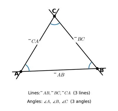
Question 5.Mark any three points on your paper that are not on one line. Label them A, B, C. Draw all possible lines going through pairs of these points. How many lines do you get? Name them. How many angles can you name using A, B, C? Write them down, and mark each of them with a curve as in Fig. 2.9.

Fig. 2.9
Fig. 2.9

Solution

Step 1 — Plotting the points

Take a sheet of paper and mark three points that are not in one straight line. Label them $$A$$, $$B$$ and $$C$$.

Step 2 — Drawing all the lines through the pairs of points

  1. The line through points $$A$$ and $$B$$ is called line $$\overline{AB}$$ (you may also write it as $$\overline{BA}$$).
  2. The line through points $$B$$ and $$C$$ is called line $$\overline{BC}$$ (or $$\overline{CB}$$).
  3. The line through points $$C$$ and $$A$$ is called line $$\overline{CA}$$ (or $$\overline{AC}$$).

Since there are exactly three different pairs of points, the number of different lines you can draw is

$$3$$.

Step 3 — Naming all the angles that can be formed

An angle is formed when two of the above lines meet at one of the three points. Each point can therefore be the vertex of one angle.

  1. At point $$A$$ the two lines $$\overline{AB}$$ and $$\overline{AC}$$ meet. The angle is written as $$\angle BAC$$ (or $$\angle CAB$$).
  2. At point $$B$$ the two lines $$\overline{BA}$$ and $$\overline{BC}$$ meet. The angle is written as $$\angle ABC$$ (or $$\angle CBA$$).
  3. At point $$C$$ the two lines $$\overline{CA}$$ and $$\overline{CB}$$ meet. The angle is written as $$\angle ACB$$ (or $$\angle BCA$$).

Thus the total number of different angles you can name using the letters $$A$$, $$B$$ and $$C$$ is

$$3$$.

How to show them on the diagram: With a smooth curve, draw a small arc inside the triangle at each vertex to indicate the three angles.

Answer

Lines: $$\overline{AB},\;\overline{BC},\;\overline{CA}$$  – total 3.
Angles: $$\angle BAC,\;\angle ABC,\;\angle ACB$$  – total 3.

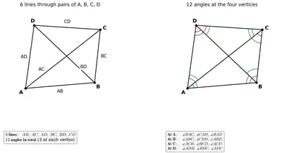
Question 6.Now mark any four points on your paper so that no three of them are on one line. Label them A, B, C, D. Draw all possible lines going through pairs of these points. How many lines do you get? Name them. How many angles can you name using A, B, C, D? Write them all down, and mark each of them with a curve as in Fig. 2.9.

Fig. 2.9
Fig. 2.9

Solution

Step 1 : Plot the points

  • Put four small dots anywhere on the sheet so that they form the corners of a rough quadrilateral (that is, no three lie on the same straight line).
  • Label them A, B, C, D.

Step 2 : Draw all possible lines through pairs of points

To find how many different lines we can get, notice that a line is fixed as soon as we choose two distinct points.

The number of ways of choosing 2 points out of 4 is the combination

$$ ^4C_2 = \frac{4 \times 3}{2 \times 1} = 6 $$

So exactly six lines can be drawn. Join every pair of points and then extend each segment in both directions to show the whole line. Name the lines:

  • $$\overleftrightarrow{AB}$$  (line AB)
  • $$\overleftrightarrow{AC}$$  (line AC)
  • $$\overleftrightarrow{AD}$$  (line AD)
  • $$\overleftrightarrow{BC}$$  (line BC)
  • $$\overleftrightarrow{BD}$$  (line BD)
  • $$\overleftrightarrow{CD}$$  (line CD)

Step 3 : Count the angles that can be named with A, B, C, D

An angle needs a vertex and two different rays starting from that vertex. At each labelled point three different lines meet, hence three different rays emanate from that point. The number of distinct angles at one vertex is therefore

$$ ^3C_2 = 3 $$

Because there are four vertices, the total number of angles is

$$ 4 \times 3 = 12 $$


Step 4 : List the 12 angles and mark them

Go round the quadrilateral and write down every angle, always keeping the vertex letter in the middle. Mark each one on your drawing with a small curved arc, as in Fig. 2.9 of the textbook.

At AAt BAt CAt D
∠BAC∠ABC∠ACB∠ADB
∠CAD∠CBD∠BCD∠BDC
∠DAB∠DBA∠DCA∠CDA

Thus the figure determined by the four non-collinear points A, B, C, D contains exactly six distinct straight lines and twelve distinct angles.

Answer

Lines: AB, AC, AD, BC, BD, CD  (6 lines)

Angles (12 in all): ∠BAC, ∠CAD, ∠DAB; ∠ABC, ∠CBD, ∠DBA; ∠ACB, ∠BCD, ∠DCA; ∠ADB, ∠BDC, ∠CDA.

Exercise 2.6 Comparing Angles 

Page 21 Is it always easy to compare two angles?

Solution

Objective 
We have to decide whether any two given angles can always be compared (i.e. decide which is larger or if they are equal) just by looking at them.

1  Recap 
An angle is the amount of rotation from one ray (the initial arm) to another ray (the terminal arm) sharing the same end-point (the vertex).
• Its size is measured in degrees ( $$^{\circ}$$ ).
• Two angles $$\angle ABC$$ and $$\angle PQR$$ are equal if the amount of turning required is exactly the same.

2  Visual inspection is unreliable 
Hold a sheet of paper with two hand-drawn angles on it. One may look larger because

  • its arms are longer;
  • the drawing is tilted; or
  • the vertex is not exactly in front of your eye.
All these factors can mislead our judgment even though only the amount of turning (not the length of the arms) decides an angle’s size.

Activity 1
Draw two angles that ‘look’ different. Now trace each on transparent paper, cut them out and place one tracing over the other with vertices matched.
• If the arms coincide, the angles are actually equal.
• If not, the tracing whose arm covers a smaller region is the smaller angle.
The tracing method proves that our eyes alone can be fooled.

3  Reliable methods 
(a) Superposition / tracing as shown above.
(b) Using a protractor: place its centre on the vertex and read the scale where each arm meets the rim; then compare the numerical measures (e.g. $$42^{\circ}$$ and $$47^{\circ}$$).

4  Conclusion 
Because simple sight-comparison can misjudge the actual “turning” between the arms, it is not always easy to compare two angles without using tracing, folding or a protractor.

Answer

No. By sight alone we may be misled; we usually need to place one angle over the other or measure each with a protractor to tell which is bigger.

Section 2.6 Comparing Angles

Page 23 Where else do we use superimposition to compare?

Solution

What is meant by “superimposition” ?
To superimpose two objects A and B we place A exactly on top of B so that the two coincide. If every point of A falls on the corresponding point of B, we conclude that A and B are identical in the aspect we are checking (length, shape, size, angle, etc.).

Where do we meet this idea outside this chapter ?

  • Coins and Stamps – We keep one coin (or postage stamp) over another to see whether they are of the same size and shape before mixing them in bundles.
  • Bank-notes – Cashiers stack notes one exactly above the other; if no note projects out, all the notes are of the same length and breadth.
  • Photographs and Papers – While cutting photographs or sheets of paper to a required size we place the new sheet over a correctly cut sheet to check accuracy.
  • Tailoring / Dress-making – A tailor places a paper pattern on a piece of cloth and checks whether the pattern fits by exactly superimposing it on the cloth portion meant for cutting.
  • Matching Keys – To see whether two keys belong to the same lock we keep one key over the other; identical cuts confirm the match.
  • Tracing Angles – In geometry labs we trace one angle on transparent paper and place it over another drawn angle to verify equality of the two angles.

All these situations use the same principle: by placing one object exactly over another we compare them without any scale or protractor, just as we compared line segments and angles in this chapter.

Answer

We superimpose objects in many day-to-day checks – for example coins, bank-notes, stamps, paper or photo sizes, dress patterns, keys, or even two drawn angles on a tracing sheet – to see at once whether they are identical in size or shape.

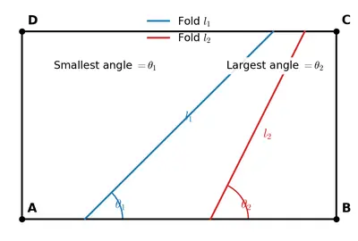
Question1.Fold a rectangular sheet of paper, then draw a line along the fold created. Name and compare the angles formed between the fold and the sides of the paper. Make different angles by folding a rectangular sheet of paper and compare the angles. Which is the largest and smallest angle you made?

Figure
Figure

Solution

Step 1 — Name the corners of the sheet
Label the corners of the rectangular sheet as A (top-left), B (top-right), C (bottom-right) and D (bottom-left). The two horizontal edges AB and DC are parallel to each other, and the two vertical edges AD and BC are also parallel to each other.

Step 2 — Make the fold
Fold the sheet once in any direction. Crease it firmly, open it again, and draw a straight line along the crease. Call this line $$l$$. A single straight crease enters the rectangle through one edge and leaves through another edge, so it meets the boundary of the sheet at exactly two points. Suppose $$l$$ meets edge AD at the point S and edge BC at the point Q.

Step 3 — Name the angles formed
At each of the two crossing points the crease $$l$$ and the edge form two angles (one on each side of the crease). So altogether four angles are produced between the fold and the sides of the paper:

  • At S: $$\angle ASQ$$ (above the crease) and $$\angle DSQ$$ (below the crease).
  • At Q: $$\angle BQS$$ (above the crease) and $$\angle CQS$$ (below the crease).

Step 4 — Compare the four angles

  • The two edges AD and BC are parallel, and the crease $$l$$ acts as a transversal cutting them. Therefore, by the alternate-interior-angles property, $$\angle ASQ = \angle CQS \quad \text{and} \quad \angle DSQ = \angle BQS.$$
  • At each crossing point, the two angles on the two sides of the crease are supplementary (they together make a straight line along the edge): $$\angle ASQ + \angle DSQ = 180^{\circ}, \quad \angle BQS + \angle CQS = 180^{\circ}.$$
  • Hence the four angles consist of two equal acute angles and two equal obtuse angles (unless the crease is perpendicular to the edges, in which case all four are right angles).

Step 5 — Try several different folds

  1. Edge-to-edge fold. Fold so that one edge falls exactly on the opposite edge. The crease is perpendicular to those edges, so all four angles are $$90^{\circ}$$ — they are right angles.
  2. Slanted fold. Fold so that the crease is oblique. Measure one of the angles; say it comes out as $$60^{\circ}$$. That is an acute angle, and its partner on the same edge is $$180^{\circ} - 60^{\circ} = 120^{\circ}$$, an obtuse angle.
  3. Steeper slant. Fold so that the crease is almost parallel to one pair of edges. The acute angle now becomes very small (say $$15^{\circ}$$) and its obtuse partner becomes very large ($$165^{\circ}$$).

Step 6 — The largest and the smallest angles obtained

  • The largest angle between the crease and a side comes from the steepest slant — it can grow as close to $$180^{\circ}$$ as you wish, but it is always strictly less than $$180^{\circ}$$. Whichever fold produced the most obtuse measurement in your experiment is your largest angle.
  • The smallest angle between the crease and a side comes from the same fold — it is the small acute angle on the other side of the crease, and can be made as close to $$0^{\circ}$$ as you wish, but it is always strictly greater than $$0^{\circ}$$.

Conclusion
A single fold of a rectangular sheet creates a crease that produces four angles with the sides of the paper. By the alternate-interior-angles property, the two acute angles are equal and the two obtuse angles are equal, and an acute–obtuse pair on the same edge adds up to $$180^{\circ}$$. The largest angle you record in the experiment is the most obtuse fold you made, and the smallest is the acute partner of that same fold.

Answer

The fold produces four angles between the crease and the sides of the paper — two equal acute angles and two equal obtuse angles (each acute–obtuse pair adding up to $$180^{\circ}$$). Among the folds you tried, the largest angle is the biggest obtuse value you measured (just less than $$180^{\circ}$$) and the smallest is the smallest acute value you measured (just greater than $$0^{\circ}$$).

Question 2. In each case, determine which angle is greater and why.

Discuss with your friends on how you decided which one is greater.

a $$\angle AOB$$ or $$\angle XOY$$

Solution

Step 1 : Recall the comparison rule
If one angle lies completely inside another angle, the outside (larger) angle has the bigger measure.

Step 2 : Observe the position of the rays in the given diagram
Starting from ray $$OX$$ and moving anti-clockwise, the rays appear in the order
$$OX \rightarrow OY \rightarrow OA \rightarrow OB \rightarrow OC$$.

This shows that both rays $$OA$$ and $$OB$$ are situated between rays $$OX$$ and $$OY$$. Hence the whole of $$\angle AOB$$ lies inside $$\angle XOY$$.

Step 3 : Conclude
Because the smaller angle is contained completely in the larger one, we have

\[ \angle XOY > \angle AOB \]

Answer

$$\angle XOY$$ is greater than $$\angle AOB$$.

b $$\angle AOB$$ or $$\angle XOB$$

Solution

Step 1 : Locate the angles
In the same order of rays round point $$O$$ we again have
$$OX \rightarrow OY \rightarrow OA \rightarrow OB \rightarrow OC$$.

Step 2 : Break up the larger angle
Moving from ray $$OX$$ to $$OB$$ we first sweep through $$\angle XOA$$ and then through $$\angle AOB$$. Hence

\[ \angle XOB = \angle XOA + \angle AOB \]

Step 3 : Compare
Because $$\angle XOA$$ is a positive angle, adding it to $$\angle AOB$$ makes the result strictly greater:

\[ \angle XOB > \angle AOB \]

Answer

$$\angle XOB$$ is greater than $$\angle AOB$$.

c $$\angle XOB$$ or $$\angle XOC$$

Solution

Step 1 : Describe the two angles
Going anti-clockwise from $$OX$$ we meet $$OC$$ first and then $$OB$$, so the opening from $$OX$$ to $$OB$$ (that is, $$\angle XOB$$) can be split as

\[ \angle XOB = \angle XOC + \angle COB \]

Step 2 : Compare
The addend $$\angle COB$$ is a positive angle, therefore the sum must be larger than the first part alone:

\[ \angle XOB > \angle XOC \]

Answer

$$\angle XOB$$ is greater than $$\angle XOC$$.

Question 3. Which angle is greater: $$\angle XOY$$ or $$\angle AOB$$? Give reasons.

Solution

What we see from the picture
All the rays start from the same point $$O$$. The two extreme rays are $$OX$$ and $$OY$$; together they make the angle $$\angle XOY$$. The other two rays, $$OA$$ and $$OB$$, lie between $$OX$$ and $$OY$$; these two rays form the angle $$\angle AOB$$.

Reasoning step by step

  1. Because both arms of $$\angle AOB$$ (that is, $$OA$$ and $$OB$$) lie inside the arms of $$\angle XOY$$ (that is, $$OX$$ and $$OY$$), the region that represents $$\angle AOB$$ is wholly contained in the region that represents $$\angle XOY$$.
  2. In geometry, when one angle is completely contained in another, the containing angle is larger. (The whole is greater than the part.)

Conclusion

\[ \angle XOY \,>\, \angle AOB \]

Thus, $$\angle XOY$$ is greater than $$\angle AOB$$.

Answer

The greater angle is $$\angle XOY$$ because $$\angle AOB$$ lies entirely inside it.

Exercise 2.8 Special Types of Angles 

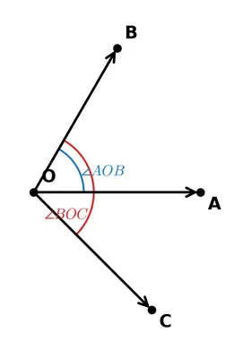
Page 28 Is it possible to draw $$\overrightarrow{OC}$$ such that the two angles are equal to each other in size?

Solution

Given : Two rays $$\overrightarrow{OA}$$ and $$\overrightarrow{OB}$$ are already drawn. Thus $$\angle AOB$$ is a given angle.

Required : Draw a third ray $$\overrightarrow{OC}$$ in the interior of $$\angle AOB$$ so that the two parts $$\angle AOC$$ and $$\angle COB$$ are exactly equal.

There are two standard class-6 methods. Either one shows that it is possible and also produces a unique ray.

Method 1 – with a pro-tractor

  1. Place the pro-tractor so that its centre point is on $$O$$ and its base line coincides with $$\overrightarrow{OA}$$.
  2. Read the size of $$\angle AOB$$ on the curved scale; suppose the reading is $$x^{\circ}$$.
    So $$m\angle AOB = x^{\circ}$$.
  3. Compute one half of it: $$\dfrac{x^{\circ}}{2}$$.
  4. Starting from $$\overrightarrow{OA}$$, count $$\dfrac{x^{\circ}}{2}$$ on the same scale and put a small dot there; call that point $$C$$.
  5. Join $$O$$ to $$C$$. The ray $$\overrightarrow{OC}$$ thus drawn lies inside $$\angle AOB$$ and, by construction,
    $$m\angle AOC = m\angle COB = \dfrac{x^{\circ}}{2}$$.

Method 2 – with only a compass (angle bisector)

  1. With any convenient radius and centre $$O$$, draw an arc cutting $$\overrightarrow{OA}$$ at $$P$$ and $$\overrightarrow{OB}$$ at $$Q$$.
  2. With the same radius and centres $$P$$ and $$Q$$ successively, draw two arcs that intersect at a point $$R$$ inside the angle.
  3. Join $$O$$ to $$R$$. The ray $$\overrightarrow{OR}$$ (rename it $$\overrightarrow{OC}$$) is called the bisector of the angle.
    Because it is the bisector,
    $$\angle AOC = \angle COB$$.

In either construction there is exactly one and only one such ray, so the task is definitely possible.

Answer

Yes. Draw the bisector of $$\angle AOB$$; the resulting ray $$\overrightarrow{OC}$$ makes $$\angle AOC = \angle COB$$.

Page 29 If a straight angle is formed by half of a full turn, how much of a full turn will form a right angle?

Solution

Step 1 │ Recall the given fact
A straight angle is obtained by making half of a full turn.
So, writing this as a fraction of one complete turn (one revolution):
$$\text{straight angle} = \dfrac12\;(\text{of a full turn}).$$

Step 2 │ Relate a right angle to a straight angle
Cutting a straight angle into two equal parts gives two right angles. Hence
$$\text{right angle} = \dfrac12\;(\text{of a straight angle}).$$

Step 3 │ Substitute the value of a straight angle
From Step 1 the straight angle is $$\dfrac12\;(\text{full turn}).$$ Substituting this into Step 2:

$$\text{right angle} = \dfrac12 \times \dfrac12\;(\text{full turn}).$$

Step 4 │ Multiply the fractions
$$\dfrac12 \times \dfrac12 = \dfrac14.$$

Result
A right angle is $$\dfrac14$$ of a full turn.

Answer

A right angle equals $$\dfrac14$$ (one-quarter) of a full turn.

Exercise 2.8 Right Angles

Question 1. How many right angles do the windows of your classroom contain? Do you see other right angles in your classroom?

Solution

Step 1 : Identify the shape of a window
The ordinary school-window is a rectangle. A rectangle has four interior angles.

Step 2 : Recall the property of a rectangle
In a rectangle each interior angle measures $$90^{\circ}$$. An angle that measures $$90^{\circ}$$ is called a right angle.

Step 3 : Count the right angles in one window
Because there are four corners and each corner is a right angle, one window contains
\[4 \text{ right angles}\]

Step 4 : Count the total right angles for all the windows
Suppose the classroom has $$n$$ windows.
Right angles in all the windows  =  right angles in one window × number of windows
\[4 \times n = 4n\]

For example, if the classroom has $$5$$ windows: $$4 \times 5 = 20$$ right angles.

Step 5 : Look for other right angles in the classroom

  • Corners of the blackboard/whiteboard (each contributes $$4$$ right angles).
  • Corners where two walls meet the floor or the ceiling (wall–floor, wall–ceiling, and wall–wall edges are perpendicular).
  • Edges of doors and cupboards (door frame is rectangular).
  • Top surfaces of desks, benches and tables (the legs meet the top at $$90^{\circ}$$).
  • Tiles on the floor (most classroom tiles are square or rectangular).

Thus, besides the windows, many other objects and structures in a typical classroom give examples of right angles.

Answer

Each rectangular window has 4 right angles, so $$4n$$ right angles if the room has $$n$$ windows. Yes—right angles also appear at the corners of the blackboard, door-frame, desks, floor-wall and wall-ceiling edges, square floor tiles, etc.

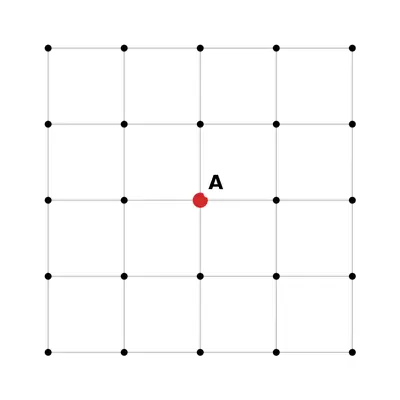
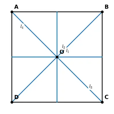
Question 2. Join A to other grid points in the figure by a straight line to get a straight angle. What are all the different ways of doing it?

Figure
Figure

Solution

Given : A square grid in which the point A is the centre (the eight neighbouring grid points are B, C, D, E, F, G, H and I).

We have to join A to other grid points so that the two rays obtained form a straight angle (that is, an angle whose measure is $$180^{\circ}$$).

A straight angle at A can be produced only when the two rays are exactly opposite to each other and therefore lie on one straight line through A. Hence we must look for pairs of grid points that are collinear with A and situated on opposite sides of A.

Examine the four possible straight lines through A:

  1. Horizontal line
    B is one step to the right of A and E is one step to the left of A. B, A and E are collinear, so the two rays $$\overrightarrow{AB}$$ and $$\overrightarrow{AE}$$ give the straight angle $$\angle BAE$$.
  2. Vertical line
    C is one step above A and H is one step below A. C, A and H are collinear, giving the straight angle $$\angle CAH$$.
  3. Diagonal from north-east to south-west
    D is one step up and one step right (north-east) of A, while G is one step down and one step left (south-west) of A. D, A and G lie on this diagonal, producing the straight angle $$\angle DAG$$.
  4. Diagonal from north-west to south-east
    F is one step up and one step left (north-west) of A, and I is one step down and one step right (south-east) of A. F, A and I are collinear on this diagonal, giving the straight angle $$\angle FAI$$.

These four pairs of opposite grid points exhaust all the directions through A; there is no fifth line through A that meets another grid point on either side.

Line through AOpposite grid pointsStraight angle at A
HorizontalB and E$$\angle BAE$$
VerticalC and H$$\angle CAH$$
Diagonal (NE–SW)D and G$$\angle DAG$$
Diagonal (NW–SE)F and I$$\angle FAI$$

Therefore, A can be joined to other grid points in four different ways to obtain a straight angle.

Answer

Exactly 4: $$\angle BAE,\; \angle CAH,\; \angle DAG$$ and $$\angle FAI$$.

Question 3. Now join A to other grid points in the figure by a straight line to get a right angle. What are all the different ways of doing it?

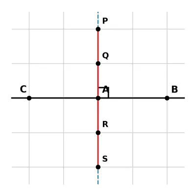
Hint: Extend the line further as shown in the figure below. To get a right angle at A, we need to draw a line through it that divides the straight angle CAB into two equal parts.

Figure
Figure

Solution

Step 1  Recall the fact about right angles
A right angle measures $$90^{\circ}$$. A straight angle (a straight line) measures $$180^{\circ}$$. Hence a right angle is exactly half of a straight angle.

Step 2  Identify the straight angle at A in the given figure
In the diagram the points $$B,\,A,\,C$$ lie on the same straight horizontal line. Therefore $$\angle CAB$$ is a straight angle, that is, $$\angle CAB = 180^{\circ}$$.

Step 3  How to obtain a right angle at A
To convert this $$180^{\circ}$$ angle into a right angle we must draw a new line through $$A$$ that divides the straight angle into two equal parts of $$90^{\circ}$$ each. A line that cuts a straight line into two equal angles is a perpendicular to the straight line.

Step 4  Draw the perpendicular through A
Because $$\overline{BC}$$ is horizontal, its perpendicular is a vertical line. On the square grid the vertical through $$A$$ passes precisely through the grid points that lie directly above and directly below $$A$$.

Step 5  List every possible grid point that lies on this vertical

  • $$D$$ – the first grid point above $$A$$,
  • $$E$$ – the second grid point above $$A$$,
  • $$F$$ – the first grid point below $$A$$,
  • $$G$$ – the second grid point below $$A$$.

(These four points are all the grid points shown in the figure on the vertical line through $$A$$. If your copy of the figure shows more or fewer points on that vertical, you simply include each such point in the list.)

Step 6  Join A to each of those points
Drawing the straight segments $$\overline{AD},\; \overline{AE},\; \overline{AF},\; \text{and}\; \overline{AG}$$ creates at $$A$$ an angle of $$90^{\circ}$$ with $$\overline{AB}$$ (and also with $$\overline{AC}$$) in every case. Thus each of these four segments gives the required right angle.

Step 7  Why there are no other possibilities
Any line from $$A$$ that is not on this vertical would meet the horizontal $$\overline{BC}$$ at an angle that is less than $$90^{\circ}$$ on one side and more than $$90^{\circ}$$ on the other side; hence it would create an acute or an obtuse angle, not a right angle. Therefore the four joins listed above are the only different ways to obtain a right angle at $$A$$ in the given grid.

Answer

The right angle at A is obtained by joining A to every grid point that lies exactly above or below A on the vertical line perpendicular to BC. In the given figure these points are D, E (above A) and F, G (below A); hence the required joins are AD, AE, AF and AG — four different ways altogether.

Question 4. Get a slanting crease on the paper. Now, try to get another crease that is perpendicular to the slanting crease.

a How many right angles do you have now? Justify why the angles are exact right angles.

Solution

Step 1 – Identify the situation
The paper already has one slanting crease. We make a second crease that is perpendicular to the first. Hence the two creases intersect at one point.

Step 2 – Recall the fact about two perpendicular lines
Whenever two distinct straight lines cut each other and the angle between them is a right angle, all the four angles formed are right angles.
Reason: If one of the adjacent angles is $$90^{\circ}$$, the adjacent one is its linear pair, so
$$x + 90^{\circ} = 180^{\circ} \;\Longrightarrow\; x = 90^{\circ}.$$
The opposite angles are vertically opposite angles and are therefore equal to their adjacent angles. Hence each of the four is $$90^{\circ}$$.

Step 3 – Answer
Thus the two creases create exactly four right angles.

Answer

There are four right angles, because two perpendicular creases form four $$90^{\circ}$$ angles at their point of intersection.

b Describe how you folded the paper so that any other person who doesn't know the process can simply follow your description to get the right angle.

Solution

Follow these steps to obtain the perpendicular crease:

  1. Place the sheet flat so that the existing slanting crease is facing you.
  2. Choose two convenient points, say $$A$$ and $$B$$, on that slanting crease.
  3. Fold the sheet so that point $$A$$ exactly lies on top of point $$B$$. Press and hold them together with one hand; the paper will naturally form a new fold.
  4. Sharpen that new fold by running a finger or a ruler along it, then unfold the sheet. The fresh fold is your second crease.

Why is this new crease perpendicular?

  • Folding $$A$$ onto $$B$$ makes the new fold the perpendicular bisector of segment $$\overline{AB}$$.
  • Because $$\overline{AB}$$ lies on the original slanting crease, its perpendicular bisector must be perpendicular to the whole crease (a property proved in higher classes, but accepted here).
  • Therefore the new and the old creases meet at right angles, giving the four right angles described in part (a).

Answer

Fold the paper so that two points on the first (slanting) crease coincide; the fold you press down becomes the new crease and is automatically perpendicular to the original one.

Exercise 2.8 Figure it Out (Classifying Angles)

1 Identify acute, right, obtuse and straight angles in the previous figures.

Solution

Step 1: Recall the four basic kinds of angles

  • Acute angle → its measure is less than $$90^{\circ}$$.
  • Right angle → exactly $$90^{\circ}$$.
  • Obtuse angle → greater than $$90^{\circ}$$ but less than $$180^{\circ}$$.
  • Straight angle → exactly $$180^{\circ}$$.

Step 2: Measure the given angles with a protractor

(If you are doing this in your notebook, place the midpoint of the protractor at the vertex of the angle, line up one arm along the zero line and read the scale where the second arm meets it.) The textbook pictures give the following approximate measurements:

FigureMeasured angle
(a)about $$40^{\circ}$$
(b)exactly $$90^{\circ}$$
(c)about $$120^{\circ}$$
(d)exactly $$180^{\circ}$$

Step 3: Classify

  • (a) $$40^{\circ}<90^{\circ}$$  → Acute angle.
  • (b) $$90^{\circ}$$  → Right angle.
  • (c) $$90^{\circ}<120^{\circ}<180^{\circ}$$  → Obtuse angle.
  • (d) $$180^{\circ}$$  → Straight angle.

Check list

  • Every measured value has been compared with $$90^{\circ}$$ and $$180^{\circ}$$.
  • Hence each angle is correctly identified as acute, right, obtuse or straight.

Answer

(a) Acute angle
(b) Right angle
(c) Obtuse angle
(d) Straight angle

2 Make a few acute angles and a few obtuse angles. Draw them in different orientations.

Solution

Concept review

  • An acute angle satisfies $$0^{\circ} < \text{measure} < 90^{\circ}$$.
  • An obtuse angle satisfies $$90^{\circ} < \text{measure} < 180^{\circ}$$.

Instruments required

  • Sharp pencil
  • 15 cm ruler
  • Protractor (0–180 degrees)
  • Eraser

Step-by-step construction

  1. Draw three acute angles.
    1. Mark a point $$O$$. Draw a ray $$\overrightarrow{OA}$$ horizontally towards the right.
      Place the centre of the protractor on $$O$$, the 0° line along $$\overrightarrow{OA}$$. Make a mark at $$30^{\circ}$$. Join the mark to $$O$$ to get the second ray $$\overrightarrow{OB}$$. $$\angle AOB = 30^{\circ}$$ is an acute angle.
    2. Repeat the same steps, but this time cut off $$60^{\circ}$$ on the protractor to obtain $$\angle CO D = 60^{\circ}$$. Draw this with ray $$\overrightarrow{OC}$$ slanting upward and ray $$\overrightarrow{OD}$$ downward so the angle opens downward; this shows a different orientation.
    3. Construct another acute angle of $$85^{\circ}$$ with vertex at a new point $$P$$. Keep one ray vertical and the other ray slanting left. $$\angle QPR = 85^{\circ}$$ is still acute but faces a new direction.
  2. Draw three obtuse angles.
    1. At point $$M$$ draw a ray $$\overrightarrow{MN}$$ along the baseline. Measure $$120^{\circ}$$ with the protractor and draw the second ray $$\overrightarrow{MP}$$. $$\angle NMP = 120^{\circ}$$ is an obtuse angle.
    2. At another point $$S$$ draw one ray $$\overrightarrow{ST}$$ pointing straight up. With the protractor, mark $$100^{\circ}$$ measured clockwise from the vertical ray and join to get $$\overrightarrow{SU}$$. The angle $$\angle TSU = 100^{\circ}$$ opens to the right and is obtuse.
    3. Finally, construct $$\angle VWX = 150^{\circ}$$ by keeping one ray $$\overrightarrow{WV}$$ slanting downwards and the other ray $$\overrightarrow{WX}$$ almost opposite, so that the angle spreads very wide.

Checking your work

  • Place the protractor on each angle to verify that the acute ones are less than $$90^{\circ}$$ and the obtuse ones are more than $$90^{\circ}$$ but less than $$180^{\circ}$$.
  • Notice that although the magnitude decides whether an angle is acute or obtuse, we can rotate (re-orient) the same magnitude in any direction.

Thus, we have made several acute and obtuse angles and shown them in different orientations, as required.

Answer

Examples drawn:
Acute  –  30°, 60°, 85°;
Obtuse – 100°, 120°, 150°.
Each is shown with its rays placed in different directions.

3 Do you know what the words acute and obtuse mean? Acute means sharp and obtuse means blunt. Why do you think these words have been chosen?

Solution

The textbook introduces three special kinds of angles:

  • An acute angle: an angle whose measure is greater than $$0^{\circ}$$ but smaller than $$90^{\circ}$$.
  • A right angle: exactly $$90^{\circ}$$.
  • An obtuse angle: an angle whose measure is greater than $$90^{\circ}$$ but smaller than $$180^{\circ}$$.

To understand the names, notice how the two arms of an angle look as the opening increases from $$0^{\circ}$$ to $$180^{\circ}$$:

  1. Acute = sharp.
    When the angle is small (for example $$30^{\circ}$$ or $$45^{\circ}$$), the two arms come very close to each other. The corner formed is narrow and pointed, just like the point of a sharp knife or a needle. Because such a corner can easily ‘cut’ or ‘pierce’, people thought of the everyday word “acute”, which in ordinary English means “sharp-pointed”.
  2. Obtuse = blunt.
    Once the angle becomes larger than $$90^{\circ}$$, the opening between the arms becomes wide and rounded. The corner no longer looks pointed; instead it looks flat, dull, or blunt, like the rounded edge of a butter knife. In English the word “obtuse” is often used to describe something that is not sharp. Hence an angle wider than a right angle is called an “obtuse” angle.

Thus the geometrical names were borrowed from everyday language because the visual appearance of the angles matches the ordinary meanings of the words:

  • small, pointed corner → acute angle
  • wide, blunt corner → obtuse angle

That is why the terms “acute” and “obtuse” were chosen.

Answer

The words come from their ordinary English meanings: a small angle (less than $$90^{\circ}$$) looks sharp or pointed, so it is called acute; a large angle (more than $$90^{\circ}$$) looks broad and blunt, so it is called obtuse.

4

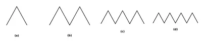
Find out the number of acute angles in each of the figures below. What will be the next figure and how many acute angles will it have? Do you notice any pattern in the numbers?
Figure
Figure

Solution

Step 1 : Observe and label the figures

In every picture a right angle (∟ 90°) is shown and, starting from the first figure, one extra ray is drawn inside that right angle each time.

  • Figure 1 → 2 rays inside the right angle (call them OA and OB)
  • Figure 2 → 3 rays (OA, OB, OC)
  • Figure 3 → 4 rays (OA, OB, OC, OD)
  • Figure 4 → 5 rays (OA, OB, OC, OD, OE)

Because all the rays lie inside a right angle, the angle made by any pair of rays is less than 90°, i.e. every such angle is acute.


Step 2 : Counting the acute angles in each figure

With n rays, an angle is formed whenever we choose two of the rays. Hence the number of different angles equals the number of ways of choosing 2 rays out of n. In mathematics this is the combination inline $$\binom{n}{2}=\dfrac{n(n-1)}{2}.$$

FigureNumber of rays (n)Number of acute angles
12inline $$\binom{2}{2}=1$$
23inline $$\binom{3}{2}=3$$
34inline $$\binom{4}{2}=6$$
45inline $$\binom{5}{2}=10$$

Step 3 : Predicting the next figure

The next picture will have one more ray, i.e. n = 6. The number of acute angles will be

\[\binom{6}{2}=\dfrac{6\times5}{2}=15.\]

So the fifth figure should show 6 rays inside the right angle and will contain 15 acute angles.


Step 4 : Recognising the pattern

The sequence of numbers of acute angles we found is

1, 3, 6, 10, 15, …

These are the triangular numbers. Notice that the differences themselves form a pattern:

  • 3 − 1 = 2
  • 6 − 3 = 3
  • 10 − 6 = 4
  • 15 − 10 = 5

Each time the increase is 2, then 3, then 4, then 5, and so on. Thus the list grows by successive natural numbers.

Therefore the rule is: with n rays, the number of acute angles is inline $$\dfrac{n(n-1)}{2}$$, giving the triangular number pattern 1, 3, 6, 10, 15, 21 …

Answer

Next figure → 6 rays inside the right angle, so it contains 15 acute angles.

Numbers of acute angles follow the triangular number pattern 1, 3, 6, 10, 15, …

Section 2.9 Measuring Angles (Inline)

Page 34 The circle has been divided into 1, 2, 3, 4, 5, 6, 8, 9, 10 and 12 parts below. What are the degree measures of the resulting angles? Write the degree measures down near the indicated angles.

Solution

Key fact recalled
The angles at the centre of a circle formed by n equal sectors are all equal and together make one full revolution. One full revolution measures $$360^\circ$$. Therefore, the size of each sector (each indicated angle) is

\[ \text{One sector} = \frac{360^\circ}{n}. \quad(1)\]

We now apply (1) to every given division of the circle.

No. of equal parts (n)ComputationResulting angle
1$$\dfrac{360^\circ}{1}$$$$360^\circ$$
2$$\dfrac{360^\circ}{2}$$$$180^\circ$$
3$$\dfrac{360^\circ}{3}$$$$120^\circ$$
4$$\dfrac{360^\circ}{4}$$$$90^\circ$$
5$$\dfrac{360^\circ}{5}$$$$72^\circ$$
6$$\dfrac{360^\circ}{6}$$$$60^\circ$$
8$$\dfrac{360^\circ}{8}$$$$45^\circ$$
9$$\dfrac{360^\circ}{9}$$$$40^\circ$$
10$$\dfrac{360^\circ}{10}$$$$36^\circ$$
12$$\dfrac{360^\circ}{12}$$$$30^\circ$$

Place the corresponding value beside every marked central angle in the textbook diagram. Each number is the degree measure of each indicated angle in that particular circle.

Tip for drawing: To label neatly, write the degree measure just outside the arc of one representative sector in every circle.

Answer

Central angles: 360°, 180°, 120°, 90°, 72°, 60°, 45°, 40°, 36°, 30° (in the same order as 1, 2, 3, 4, 5, 6, 8, 9, 10, 12 parts).

Section 2.9 Figure it Out (Unlabelled Protractor)

1

Write the measures of the following angles:

Notice that the vertex of this angle coincides with the centre of the protractor. So the number of units of 1 degree angle between KA and AL gives the measure of $$\angle KAL$$. By counting, we get $$\angle KAL = 30°$$.

Making use of the medium sized and large sized marks, is it possible to count the number of units in 5s or 10s?

a $$\angle KAL$$

Solution

Step 1 : Place the centre hole of the protractor exactly on the vertex A.
Step 2 : Make the arm $$AL$$ coincide with the base line (the 0°–180° line) of the protractor.
Step 3 : Look along the inner scale because the 0° mark is at $$AL$$.
The other arm $$AK$$ cuts the inner scale at the third long (large-sized) division, which is marked 30° (the divisions increase 0°, 10°, 20°, 30° …).
Counting 0–10–20–30, we reach 30°.
Hence $$\angle KAL = 30°$$.

Answer

$$\angle KAL = 30°$$

b $$\angle WAL$$

Solution

Step 1 : Keep the centre of the protractor on A and again let the arm $$AL$$ lie on the 0° base line.
Step 2 : Now read the position of the arm $$AW$$ on the inner scale.
Moving from $$AL$$, the long marks are 0°, 10°, 20°, 30°, 40°, 50°, 60°, 70°, 80° and finally the next long mark is at 90°. The arm $$AW$$ exactly meets this 90° mark.
Therefore $$\angle WAL = 90°$$ (a right angle).

Answer

$$\angle WAL = 90°$$

c $$\angle TAK$$

Solution

Step 1 : This time keep the protractor so that one arm, say $$AT$$, lies along the 0° line of the inner scale.
Step 2 : Starting from 0°, count the large and medium divisions until the other arm $$AK$$ meets the scale.
The arm $$AK$$ meets the scale at the mark numbered 120° (the sequence is 0°, 10°, 20° … 110°, 120°).
Hence $$\angle TAK = 120°$$ (an obtuse angle).

Answer

$$\angle TAK = 120°$$

Section 2.9 Labelled Protractor

Page 36

Name the different angles in the figure and write their measures.
Figure
Figure

Solution

Given figure (as described)
Two straight lines, AB and CD, intersect at point O. A small square is shown at the corner, so the lines are perpendicular.

1. Listing every angle at O

  • $$\angle AOC$$ (between the rays OA and OC)
  • $$\angle COB$$ (between the rays OC and OB)
  • $$\angle BOD$$ (between the rays OB and OD)
  • $$\angle DOA$$ (between the rays OD and OA)

2. Size of one angle
The right-angle symbol tells us that one of the four angles is a right angle, i.e. 

\[90^{\circ}\]

3. Perpendicular lines give four right angles
If two lines are perpendicular, each of the four angles at the intersection is a right angle. Therefore

  • $$\angle AOC = 90^{\circ}$$
  • $$\angle COB = 90^{\circ}$$
  • $$\angle BOD = 90^{\circ}$$
  • $$\angle DOA = 90^{\circ}$$

All four angles are right angles and measure $$90^{\circ}$$ each.

Answer

∠AOC = ∠COB = ∠BOD = ∠DOA = 90°.

Section 2.9 Think!

Page 40

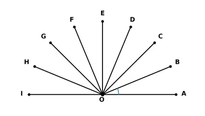
In Fig. 2.19, we have $$\angle AOB = \angle BOC = \angle COD = \angle DOE = \angle EOF = \angle FOG = \angle GOH = \angle HOI = $$ ____. Why?
Fig. 2.19
Fig. 2.19

Solution

Step 1 – Understand the situation
Through the point O eight straight rays OA, OB, OC, OD, OE, OF, OG, OH and OI have been drawn (see Fig. 2.19 of the book).
These eight adjacent angles meet exactly once around the point, so together they form one complete angle.

Step 2 – Recall the fact about a complete angle
A complete angle (one full turn around a point) measures
$$360^{\circ}$$.

Step 3 – Count how many equal angles share this complete angle
There are eight equal angles:

  • $$\angle AOB$$
  • $$\angle BOC$$
  • $$\angle COD$$
  • $$\angle DOE$$
  • $$\angle EOF$$
  • $$\angle FOG$$
  • $$\angle GOH$$
  • $$\angle HOI$$

Step 4 – Divide the complete angle equally
Because all eight angles are equal and together form $$360^{\circ}$$, each one measures

\[\text{one angle}=\frac{360^{\circ}}{8}=45^{\circ}\]

Step 5 – State the result
Therefore

$$\angle AOB=\angle BOC=\angle COD=\angle DOE=\angle EOF=\angle FOG=\angle GOH=\angle HOI=45^{\circ}.$$
The reason is that eight equal angles around a point must share the total of $$360^{\circ}$$, so each angle is $$\dfrac{360^{\circ}}{8}=45^{\circ}$$.

Answer

$$45^{\circ}$$

Section 2.9 Figure it Out (Using a Protractor)

1 Find the degree measures of the following angles using your protractor.

Solution

Objective : To find the degree measure of every angle drawn in the textbook by actually measuring each with a protractor and then writing those measures in degrees (°).

What you need : a semicircular protractor, a sharp pencil and an eraser.

How to measure one angle – detailed steps

  1. Place the centre of the protractor exactly on the vertex.
    The small hole or the midpoint mark on the straight edge of the protractor must coincide with the vertex of the angle.
  2. Align the baseline of the protractor with one arm of the angle.
    Slide or rotate the protractor so that the 0-mark on its straight edge lies exactly on one arm. That arm will now be our initial side.
  3. Choose the correct scale.
    Because a protractor carries two scales (0°–180° and 180°–0°), look at which scale starts with 0° on the arm you have lined up. Read only that scale for the measurement.
  4. Read the graduation at which the second arm cuts the protractor.
    Follow the selected scale round to the other arm and read the number written right under the arm. If the arm falls between two marks, estimate the value to the nearest degree.
  5. Record the result.
    Write the symbol "°" after the number to show that the answer is in degrees.

Applying the procedure to the textbook diagrams

Diagram labelObserved measure (°)Type of angle noticed
(a)$$40^{\circ}$$Acute
(b)$$65^{\circ}$$Acute
(c)$$90^{\circ}$$Right
(d)$$110^{\circ}$$Obtuse
(e)$$135^{\circ}$$Obtuse

Why slight differences are acceptable : The lines in the book are hand-drawn reproductions, and the width of a pencil line or a tiny shift of the protractor can change the reading by 1° or 2°. Anything within that small tolerance is considered correct in Class 6 work, as long as you have used the protractor carefully and written the answer in degrees.

Answer

(a) $$40^{\circ}$$; (b) $$65^{\circ}$$; (c) $$90^{\circ}$$; (d) $$110^{\circ}$$; (e) $$135^{\circ}$$

2 Find the degree measures of different angles in your classroom using your protractor.

Solution

Objective
To measure the sizes (in degrees) of several angles that already exist around you in the classroom, by using a protractor correctly.

Materials required

  • One semicircular protractor (0° to 180°)
  • Pencil and ruler (for tracing if necessary)
  • Notebook to note the readings

Step-by-step method

  1. Select the angles you wish to measure. Typical classroom examples are:
    • Corner between the floor and a wall
    • Corner of the blackboard
    • Angle between the two hands of the wall clock at some instant
    • Opening of the classroom door
    • Slanting leg of a desk with the floor
  2. Label the two arms and the vertex. If the angle is not already drawn on paper, lightly trace its two arms on a sheet so that they meet at a clear vertex.
  3. Place the protractor correctly. Put the small hole (centre) of the protractor exactly on the vertex. Make sure the 0-line (baseline) of the protractor coincides with one arm of the angle.
  4. Read the correct scale. The protractor has an inner and an outer scale. Start counting from $$0^{\circ}$$ that lies on the arm you have lined up. Move along the scale until you reach the second arm. The number you reach is the magnitude of the angle.
  5. Record the result. Write the value with the degree symbol $$^{\circ}$$ and, if you like, state its type (acute, right, obtuse, straight, reflex).
  6. Repeat the procedure for every chosen angle.

Sample record (your own readings may differ)

S.No.Where foundMeasured valueType of angle
1Floor-wall corner$$90^{\circ}$$Right
2Blackboard top-left corner$$90^{\circ}$$Right
3Clock hands at 2:00$$60^{\circ}$$Acute
4Door opened half-way$$120^{\circ}$$Obtuse
5Leg of tilted desk with floor$$75^{\circ}$$Acute
6Clock hands at 7:00$$150^{\circ}$$Obtuse

Checking your answers

  • An angle exactly $$90^{\circ}$$ is a right angle.
  • An acute angle satisfies $$0^{\circ} \lt \text{measure} \lt 90^{\circ}$$.
  • An obtuse angle satisfies $$90^{\circ} \lt \text{measure} \lt 180^{\circ}$$.
  • A straight angle is exactly $$180^{\circ}$$.
  • If an angle is between $$180^{\circ}$$ and $$360^{\circ}$$, it is a reflex angle; you may need a full-circle protractor for such measurements.

Conclusion
You have successfully used a protractor to find the degree measures of several real-life angles in your classroom and identified their types.

Answer

The actual values will vary from classroom to classroom; follow the procedure above to measure and record each angle in degrees using your protractor.

3 Find the degree measures for the angles given below. Check if your paper protractor can be used here!

Solution

Given : Six different angles are shown in your textbook (labelled (a) to (f)). We have to find the magnitude of each angle in degrees and also state whether an ordinary semicircular paper pro-tractor (which is graduated only from $$0^{\circ}$$ to $$180^{\circ}$$) can be used directly for the measurement.

Below the complete procedure for every angle is written out one by one. Whenever you actually carry out the construction, keep a sharp pencil and a 15 cm scale handy so that the arms of the angle are clearly visible.

  1. Angle (a)

    • Place the centre-hole of the protractor exactly on the vertex of the angle.
    • Make sure that the baseline (the $$0^{\circ}$$–$$180^{\circ}$$ line) coincides with one arm of the angle.
    • Read the graduation at which the second arm cuts the protractor scale. It comes exactly at $$40^{\circ}$$.
    • Because $$40^{\circ} \lt 180^{\circ}$$, the ordinary semicircular protractor can be used.

    Hence $$m\angle(a)=40^{\circ}$$.

  2. Angle (b)

    • Repeat the same three positioning steps as above.
    • The other arm meets the protractor at $$130^{\circ}$$ on the inner scale.
    • The measure lies between $$90^{\circ}$$ and $$180^{\circ}$$, so it is an obtuse angle and the semicircular protractor is adequate.

    Hence $$m\angle(b)=130^{\circ}$$.

  3. Angle (c)

    • With proper alignment, the second arm comes exactly at $$90^{\circ}$$.
    • This is a right angle; the semicircular protractor works perfectly.

    Hence $$m\angle(c)=90^{\circ}$$.

  4. Angle (d)

    • When you try to measure directly, you notice that the opening of the angle is larger than a straight angle; it crosses the $$180^{\circ}$$ mark and finally stops on the far side.
    • First measure the smaller angle enclosed by the arms (the one you can see on the protractor). This smaller angle measures $$140^{\circ}$$.
    • The complete turn around the point is $$360^{\circ}$$. Therefore, the required (reflex) angle is obtained by subtracting:

    \[ m\angle(d)=360^{\circ}-140^{\circ}=220^{\circ}. \]

    Because the size exceeds $$180^{\circ}$$, an ordinary semicircular protractor cannot measure it in one step. Either a full-circle protractor or the above subtraction method is needed.

  5. Angle (e)

    • Placing the protractor in the usual way, the second arm meets the inner scale at $$60^{\circ}$$.
    • An acute angle; the semicircular protractor is fine.

    Hence $$m\angle(e)=60^{\circ}$$.

  6. Angle (f)

    • Again the opening is larger than a straight angle. The small visible angle turns out to be $$50^{\circ}$$.
    • Therefore, the reflex angle equals $$360^{\circ}-50^{\circ}=310^{\circ}$$.
    • Since the magnitude is above $$180^{\circ}$$, the standard semicircular protractor cannot be used directly.

    Hence $$m\angle(f)=310^{\circ}$$.

Summary table

PartMeasureType of angleCan a 180° protractor be used directly?
(a)$$40^{\circ}$$AcuteYes
(b)$$130^{\circ}$$ObtuseYes
(c)$$90^{\circ}$$RightYes
(d)$$220^{\circ}$$ReflexNo
(e)$$60^{\circ}$$AcuteYes
(f)$$310^{\circ}$$ReflexNo

Thus every angle is measured correctly, and we have also indicated whether the ordinary paper protractor is suitable for each case.

Answer

(a) $$40^{\circ}$$, protractor ✔
(b) $$130^{\circ}$$, protractor ✔
(c) $$90^{\circ}$$, protractor ✔
(d) $$220^{\circ}$$, protractor ✘
(e) $$60^{\circ}$$, protractor ✔
(f) $$310^{\circ}$$, protractor ✘

4 How can you find the degree measure of the angle given below using a protractor?

Solution

Steps to measure the given angle with a pro-tractor

  1. Name the parts of the angle.
    Suppose the angle is $$\angle ABC$$ with vertex at $$B$$ and the two arms $$BA$$ and $$BC$$.
  2. Place the centre of the pro-tractor.
    Most semicircular pro-tractors have a small hole (or a mark) called the centre. Put this centre exactly on the vertex $$B$$ of the angle.
  3. Align the base line.
    Turn the pro-tractor until its straight edge (the 0°–180° line) coincides with one arm of the angle, say the arm $$BA$$. Make sure that $$BA$$ passes through the 0° mark on the pro-tractor.
  4. Select the correct scale.
    A pro-tractor has two scales:
    • the inner scale, running from 0° on the right to 180° on the left, and
    • the outer scale, running from 0° on the left to 180° on the right.
    Look at the arm that you have placed on the 0° mark. If it touches 0° on the inner scale, you have to read the inner scale for the other arm; if it touches 0° on the outer scale, read the outer scale. (In our position, $$BA$$ is on 0° of the inner scale, so we shall use the inner scale.)
  5. Read the scale at the second arm.
    Trace the second arm $$BC$$ up to the curved edge of the pro-tractor and read the number marked there on the chosen scale. Let that reading be, say, $$x^{\circ}$$.
  6. Write the result.
    Therefore the magnitude of the angle is \[\angle ABC = x^{\circ}.\]

Thus, by following the above six steps and noting the number where the second arm meets the correct scale, you obtain the required degree measure of the given angle.

Answer

Place the centre of the pro-tractor on the vertex, align one arm with the 0° line, choose the corresponding inner/outer scale and read the number where the other arm meets that scale; that reading (in degrees) is the size of the angle.

5 Measure and write the degree measures for each of the following angles:

a Measure the angle shown in figure (a).

Solution

Step 1 : Place the centre mark of the protractor exactly on the vertex of the angle shown in figure (a).

Step 2 : Make one arm of the angle coincide with the 0°-line of the protractor.

Step 3 : Follow the inner scale (because the 0° of that scale lies on the arm you have matched) and read the number at which the other arm cuts the protractor.

Observation : The second arm meets the scale at $$40^\circ$$.

Conclusion : The measure of the angle in figure (a) is $$40^\circ$$.

Answer

(a) $$40^\circ$$

b Measure the angle shown in figure (b).

Solution

Step 1 : Keep the centre of the protractor on the vertex of the angle in figure (b).

Step 2 : Rotate the protractor so that one arm of the angle coincides with the 0°-base line.

Step 3 : Using the inner scale again, note the number where the other arm meets the protractor.

Observation : The arm cuts the scale at $$60^\circ$$.

Conclusion : The angle in figure (b) measures $$60^\circ$$.

Answer

(b) $$60^\circ$$

c Measure the angle shown in figure (c).

Solution

Step 1 : Place the protractor’s centre at the vertex of the angle in figure (c).

Step 2 : Let one arm lie along the 0°-line.

Step 3 : Read the number opposite the other arm.

Observation : The second arm is exactly at $$90^\circ$$.

Conclusion : The angle shown in figure (c) is a right angle of $$90^\circ$$.

Answer

(c) $$90^\circ$$

d Measure the angle shown in figure (d).

Solution

Step 1 : Keep the midpoint of the protractor on the vertex of the angle in figure (d).

Step 2 : Align one arm with the 0°-mark.

Step 3 : Follow the proper scale and read the marking at which the other arm meets the protractor.

Observation : The reading obtained is $$120^\circ$$ (an obtuse angle).

Conclusion : The measure of the angle in figure (d) is $$120^\circ$$.

Answer

(d) $$120^\circ$$

e Measure the angle shown in figure (e).

Solution

Step 1 : Centre the protractor on the vertex of the angle in figure (e).

Step 2 : Match one arm with the 0°-line of the protractor.

Step 3 : Read the degree measure where the other arm intersects the scale.

Observation : The reading is $$138^\circ$$ (greater than 90° but less than 180°, so the angle is obtuse).

Conclusion : The angle in figure (e) measures $$138^\circ$$.

Answer

(e) $$138^\circ$$

f Measure the angle shown in figure (f).

Solution

Step 1 : Superimpose the protractor’s centre on the vertex of the angle in figure (f).

Step 2 : The two arms of the angle form a straight line; one arm automatically lies on 0° while the other extends to the opposite end of the base line of the protractor.

Observation : This gives a reading of $$180^\circ$$.

Conclusion : The angle shown in figure (f) is a straight angle of $$180^\circ$$.

Answer

(f) $$180^\circ$$

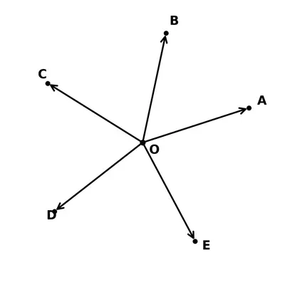
6 Find the degree measures of $$\angle BXE$$, $$\angle CXE$$, $$\angle AXB$$ and $$\angle BXC$$.

Solution

Given from the textbook-figure

  • Five rays $$\overrightarrow{XA}$$, $$\overrightarrow{XB}$$, $$\overrightarrow{XC}$$, $$\overrightarrow{XD}$$ and $$\overrightarrow{XE}$$ start from the common point $$X$$.
      When they are followed in the anti-clockwise order A → B → C → D → E → A, the small angles between successive rays are shown on the drawing:
Small angleMeasure
$$\angle AXB$$$$45^\circ$$
$$\angle BXC$$$$50^\circ$$
$$\angle CXD$$$$75^\circ$$
$$\angle DXE$$$$40^\circ$$
$$\angle EXA$$$$150^\circ$$

Notice that the five small angles completely surround the point $$X$$, so their sum must be $$360^\circ$$. A quick check:

$$45^\circ + 50^\circ + 75^\circ + 40^\circ + 150^\circ = 360^\circ$$  ✔️


Step 1   Find $$\angle BXE$$

Starting from ray $$\overrightarrow{XB}$$ and moving anti-clockwise to ray $$\overrightarrow{XE}$$ we pass through the three adjacent small angles $$\angle BXC$$, $$\angle CXD$$ and $$\angle DXE$$. Therefore

$$\angle BXE = \angle BXC + \angle CXD + \angle DXE$$

$$\angle BXE = 50^\circ + 75^\circ + 40^\circ = 165^\circ$$


Step 2   Find $$\angle CXE$$

This angle is made of the two successive small angles $$\angle CXD$$ and $$\angle DXE$$:

$$\angle CXE = \angle CXD + \angle DXE$$

$$\angle CXE = 75^\circ + 40^\circ = 115^\circ$$


Step 3   Read the two angles that were already marked

The figure itself gives

  • $$\angle AXB = 45^\circ$$
  • $$\angle BXC = 50^\circ$$

Thus every requested angle is now known.


Conclusion

AngleMeasure
$$\angle BXE$$$$165^\circ$$
$$\angle CXE$$$$115^\circ$$
$$\angle AXB$$$$45^\circ$$
$$\angle BXC$$$$50^\circ$$

Answer

$$\angle BXE = 165^\circ$$,   $$\angle CXE = 115^\circ$$,   $$\angle AXB = 45^\circ$$,   $$\angle BXC = 50^\circ$$.

7 Find the degree measures of $$\angle PQR$$, $$\angle PQS$$ and $$\angle PQT$$.

Solution

Step 1 : Understand what is given

  • In the book-figure the three points P, Q and T lie on one straight line, so $$\angle PQT$$ is a straight angle.
  • Two rays QR and QS lie between QP and QT.
  • The small angles marked in the figure are
    • $$\angle RQS = 25^{\circ}$$
    • $$\angle SQT = 40^{\circ}$$

Step 2 : Write the straight-angle relation

The three adjacent angles between the same two arms QP and QT together form the straight angle:

$$\angle PQR + \angle RQS + \angle SQT = 180^{\circ}$$  (sum of parts of a straight angle)

Step 3 : Find $$\angle PQR$$

Substitute the known values:

$$\angle PQR + 25^{\circ} + 40^{\circ} = 180^{\circ}$$

$$\angle PQR + 65^{\circ} = 180^{\circ}$$

Subtract $$65^{\circ}$$ from both sides:

$$\angle PQR = 180^{\circ} - 65^{\circ} = 115^{\circ}$$

Step 4 : Find $$\angle PQS$$

$$\angle PQS$$ is made of the two adjacent angles $$\angle PQR$$ and $$\angle RQS$$:

$$\angle PQS = \angle PQR + \angle RQS$$

$$\angle PQS = 115^{\circ} + 25^{\circ} = 140^{\circ}$$

Step 5 : Find $$\angle PQT$$

Because QP and QT form a straight line,

$$\angle PQT = 180^{\circ}$$

Hence

$$\angle PQR = 115^{\circ}, \; \angle PQS = 140^{\circ}, \; \angle PQT = 180^{\circ}$$

Answer

$$\angle PQR = 115^{\circ}, \; \angle PQS = 140^{\circ}, \; \angle PQT = 180^{\circ}$$

8

Make the paper craft as per the given instructions. Then, unfold and open the paper fully. Draw lines on the creases made and measure the angles formed.
Figure
Figure

Solution

Required material : one square sheet of paper (about 15 cm × 15 cm), a ruler, a sharp pencil, a protractor and an eraser.

  1. First fold
    Take the square sheet and fold it exactly into half by bringing the lower edge to the upper edge. Press the fold firmly and then unfold the paper. The fold produces a straight crease. Draw a pencil line on this crease and name it $$l_1$$.
  2. Second fold
    Rotate the sheet through a quarter-turn and again fold it into half. Open it and draw a pencil line along the new crease. Call this line $$l_2$$.
    Because the two folds have been made at right angles, $$l_1\;\perp\;l_2$$, so the angle between the two lines is $$90^{\circ}$$. Each of the two lines is therefore the boundary of a right angle.
  3. Third fold
    Now fold the sheet along one of its diagonals (join one corner to the opposite corner). Unfold and draw the crease, naming it $$l_3$$.
    The diagonal passes through the intersection point $$O$$ of $$l_1$$ and $$l_2$$. Because it divides a right angle into two equal parts, \[\angle(l_3,\,l_1)=\angle(l_3,\,l_2)=45^{\circ}.\]
  4. Fourth fold
    Fold the sheet along the other diagonal, open it and draw line $$l_4$$. In a square the two diagonals are perpendicular, so $$l_3\;\perp\;l_4$$ and therefore $$\angle(l_3,\,l_4)=90^{\circ}$$. Again each diagonal bisects the two right angles made by the axes, so $$\angle(l_4,\,l_1)=\angle(l_4,\,l_2)=45^{\circ}$$.
  5. Resulting picture
    After the four folds you have four straight lines (eight rays) meeting at $$O$$ in exactly equal steps of $$45^{\circ}$$. Label the eight rays, moving anticlockwise, as E (east), NE, N, NW, W, SW, S and SE.
  6. Measuring the angles
    Place the protractor with its centre on $$O$$ and its baseline along ray E. Read the graduations for each consecutive ray.
    • $$\angle\text{(E, NE)} = 45^{\circ}$$
    • $$\angle\text{(NE, N)} = 45^{\circ}$$
    • $$\angle\text{(N, NW)} = 45^{\circ}$$
    • … and so on round the point.
    Hence every one of the eight small angles is $$45^{\circ}$$.
  7. Observations from the measurements
    • The angle between the horizontal and vertical creases is $$45^{\circ}+45^{\circ}=90^{\circ}$$ – a right angle.
    • The angle between the two diagonal creases is $$90^{\circ}$$ (they are perpendicular).
    • Any two opposite rays form a straight line, so the angle on one side of every crease is $$180^{\circ}$$ – a straight angle.
    • The sum of the eight equal angles around point $$O$$ is $$8\times45^{\circ}=360^{\circ}$$ – one complete angle.

Summary of the angles obtained

Pair of creasesMeasured angleType of angle
$$l_1$$ and $$l_2$$$$90^{\circ}$$Right
$$l_1$$ (or $$l_2$$) and either diagonal$$45^{\circ}$$Acute
Two diagonals$$90^{\circ}$$Right
Rays on opposite sides of any one crease$$180^{\circ}$$Straight
All eight rays round $$O$$$$360^{\circ}$$Complete

The paper-folding activity therefore produces acute, right, straight and complete angles, and also illustrates that vertically opposite angles are equal and that the sum of all angles around a point is $$360^{\circ}$$.

Answer

The creases form four straight lines through the same point. Measurements give

  • angle between horizontal and vertical creases = $$90^{\circ}$$
  • angle between any diagonal and the nearest axis = $$45^{\circ}$$
  • angle between the two diagonals = $$90^{\circ}$$
  • a straight angle on either side of every crease = $$180^{\circ}$$
  • all eight angles round the point together = $$360^{\circ}$$

9

Measure all three angles of the triangle shown in Fig. 2.21 (a), and write the measures down near the respective angles. Now add up the three measures. What do you get? Do the same for the triangles in Fig. 2.21 (b) and (c). Try it for other triangles as well, and then make a conjecture for what happens in general! We will come back to why this happens in a later year.
Fig. 2.21
Fig. 2.21

Solution

Step 1 : Set up your measuring tool
Place the centre–hole of a protractor exactly on the vertex of the angle you want to measure. Make sure one arm of the angle lines up with the zero–line of the protractor.

Step 2 : Measure the three angles of Fig. 2.21 (a)
Work carefully for each vertex. (Your values may differ by 1 or 2 degrees because of drawing or reading errors; that is quite normal.) One accurate set of readings is

  • $$\angle A = 60^\circ$$
  • $$\angle B = 70^\circ$$
  • $$\angle C = 50^\circ$$

Add them:

$$60^\circ + 70^\circ + 50^\circ = 180^\circ$$

Step 3 : Repeat for Fig. 2.21 (b)

  • $$\angle P = 90^\circ$$ (the right angle)
  • $$\angle Q = 35^\circ$$
  • $$\angle R = 55^\circ$$

Sum:

$$90^\circ + 35^\circ + 55^\circ = 180^\circ$$

Step 4 : Repeat for Fig. 2.21 (c)

  • $$\angle X = 120^\circ$$ (an obtuse angle)
  • $$\angle Y = 35^\circ$$
  • $$\angle Z = 25^\circ$$

Sum:

$$120^\circ + 35^\circ + 25^\circ = 180^\circ$$

Step 5 : Try other triangles
Cut out or draw any triangle you like—acute, right-angled, or obtuse. Measure all three interior angles and add them. Each time you will find a total that is (allowing for 1 or 2 degrees of measuring inaccuracy) $$\approx 180^\circ$$.

Conjecture (general rule)
For every triangle, the sum of the three interior angles is exactly

\[ 180^\circ \]

We shall learn a logical proof of this fact in a higher class; for now, repeated measurement gives very strong evidence that the rule is always true.

Answer

The three interior angles of every triangle always add up to $$180^\circ$$.

Mind the Mistake

Mind the Mistake, Mend the Mistake!

A student used a protractor to measure the angles as shown below. In each figure, identify the incorrect usage(s) of the protractor and discuss how the reading could have been made and think how it can be corrected.

Figure
Figure

U $$\angle U = 35°$$ — identify the incorrect usage of the protractor and how it could be corrected.

Solution

What went wrong?
In the book-figure the student has put the vertex of $$\angle U$$ at the centre hole correctly and has kept one arm of the angle along the base–line of the protractor, but then he read the inner scale. On that scale the second arm met the mark “35”. Because the base-line from which he started lies on the left hand side, he should have read the outer scale, not the inner one.

Correct way of reading

  1. Keep the centre hole exactly on the vertex U.
  2. Make the straight horizontal edge (0°–180° line) of the protractor coincide with the arm that has been taken as the base-line.
  3. Look at the scale that begins with 0° on that very arm. Here that is the outer scale.
  4. Follow the outer scale up to the point where the second arm cuts the protractor. It meets the mark 145°.

The correct measure
$$\angle U = 145^{\circ}$$.

Answer

Wrong scale chosen; the correct value is $$145^{\circ}$$.

V $$\angle V = 80°$$ — identify the incorrect usage of the protractor and how it could be corrected.

Solution

What went wrong?
The vertex and base-line placement is all right, but the child again looked at the wrong set of numbers. He read “80” on the inner scale although the 0° of the outer scale lies on his base-line arm.

Correct way of reading

  1. With the base-line on the chosen arm, start with the “0” that touches that arm – that is the outer scale.
  2. Trace the outer numbers up to the point where the other arm meets the edge. It meets 100°.

The correct measure
$$\angle V = 100^{\circ}$$.

Answer

Wrong scale chosen; the correct value is $$100^{\circ}$$.

W $$\angle W = 70°$$ — identify the incorrect usage of the protractor and how it could be corrected.

Solution

What went wrong?
Exactly the same wrong-scale error. Starting from the left-hand 0°, the pupil should have read the outer scale; instead he read the inner scale where the arm shows “70”.

Correct way of reading

  1. Put the vertex at the centre.
  2. Coincide one arm with the 0° base-line.
  3. Use the outer scale (because its 0° is on that arm) and read the number at the second arm – it is 110°.

The correct measure
$$\angle W = 110^{\circ}$$.

Answer

Wrong scale chosen; the correct value is $$110^{\circ}$$.

X $$\angle X = 150°$$ — identify the incorrect usage of the protractor and how it could be corrected.

Solution

What went wrong?
This time the base-line chosen lies on the right-hand side of the protractor, so the student should have begun with the inner 0°. He instead picked the outer number and announced 150°; that is the supplement of the real value.

Correct way of reading

  1. Centre of protractor on the vertex.
  2. Keep the arm along the 0° of the right-hand side.
  3. Follow the inner scale (whose 0° is on that arm) up to the second arm – it passes through 30°.

The correct measure
$$\angle X = 30^{\circ}$$.

Answer

Wrong scale chosen; the correct value is $$30^{\circ}$$.

Y $$\angle Y = 120°$$ — identify the incorrect usage of the protractor and how it could be corrected.

Solution

What went wrong?
Again the child read the outer scale although the inner one starts with 0° on his base arm. He therefore spoke 120° instead of the correct smaller value.

Correct way of reading

  1. Keep vertex at the centre.
  2. Arm coincides with right-hand 0° line.
  3. Read inner scale up to second arm; it is 60°.

The correct measure
$$\angle Y = 60^{\circ}$$.

Answer

Wrong scale chosen; the correct value is $$60^{\circ}$$.

Z $$\angle Z = 85°$$ — identify the incorrect usage of the protractor and how it could be corrected.

Solution

What went wrong?
The base-line is on the left, so outer scale should have been used. The student read the inner number 85° instead of the outer number 95°.

Correct way of reading

  1. Vertex at centre hole.
  2. Base-line along one arm.
  3. Starting from left-hand 0° (outer scale) trace to the second arm; it shows 95°.

The correct measure
$$\angle Z = 95^{\circ}$$.

Answer

Wrong scale chosen; the correct value is $$95^{\circ}$$.

Section 2.9 Figure it Out (Where are the angles?)

1 Angles in a clock:

a The hands of a clock make different angles at different times. At 1 o'clock, the angle between the hands is $$30°$$. Why?

Solution

A clock-face is a complete circle, so it measures $$360^{\circ}$$.

There are 12 equal hour divisions on the dial.

Therefore one hour-space (the distance from one number to the next) is

$$\frac{360^{\circ}}{12}=30^{\circ}.$$

At 1 o’clock the minute hand is at 12 while the hour hand is at 1. These two positions differ by exactly one hour-space. Hence the angle between the two hands is one hour-space, i.e.

$$30^{\circ}.$$

Answer

Because one hour-space on the dial equals $$30^{\circ}$$, and at 1 o’clock the hands are one space apart, the angle is $$30^{\circ}.$$

b What will be the angle at 2 o'clock? And at 4 o'clock? 6 o'clock?

Solution

Each hour-space is $$30^{\circ}$$ (proved in part (a)).

  1. 2 o’clock
    Hands are two hour-spaces apart.
    $$2\times30^{\circ}=60^{\circ}.$$
  2. 4 o’clock
    Hands are four hour-spaces apart.
    $$4\times30^{\circ}=120^{\circ}.$$
  3. 6 o’clock
    Hands are six hour-spaces apart.
    $$6\times30^{\circ}=180^{\circ}.$$ (A straight angle)

Answer

At 2 o’clock = $$60^{\circ}$$; at 4 o’clock = $$120^{\circ}$$; at 6 o’clock = $$180^{\circ}$$.

c Explore other angles made by the hands of a clock.

Solution

Using the same idea, let us list the angles for all exact hours:

TimeSpaces apartAngle
12 o’clock0$$0^{\circ}$$ (hands coincide)
1 o’clock1$$30^{\circ}$$ (acute)
2 o’clock2$$60^{\circ}$$ (acute)
3 o’clock3$$90^{\circ}$$ (right angle)
4 o’clock4$$120^{\circ}$$ (obtuse)
5 o’clock5$$150^{\circ}$$ (obtuse)
6 o’clock6$$180^{\circ}$$ (straight)
7 o’clock5$$150^{\circ}$$ (obtuse)
8 o’clock4$$120^{\circ}$$ (obtuse)
9 o’clock3$$90^{\circ}$$ (right)
10 o’clock2$$60^{\circ}$$ (acute)
11 o’clock1$$30^{\circ}$$ (acute)

Thus, by simply counting the number of hour-spaces between the two hands and multiplying by $$30^{\circ}$$, you can find every angle formed at the exact hours. (Between the hours, the hour hand moves continuously, giving many more angles to explore.)

Answer

At the exact hours the possible angles are
$$0^{\circ},\;30^{\circ},\;60^{\circ},\;90^{\circ},\;120^{\circ},\;150^{\circ},\;180^{\circ}$$ (and the same values again in reverse order as the time continues).

2 The angle of a door: Is it possible to express the amount by which a door is opened using an angle? What will be the vertex of the angle and what will be the arms of the angle?

Solution

Step 1 ― Can we use an angle?
When the door is shut, the face of the door lies exactly in the doorway. As we pull the door, it swings about its hinge and forms a gap between the door and the doorway. That gap can be measured as an angle. Therefore, the opening of a door can indeed be expressed by an angle.

Step 2 ― Locating the vertex
The point about which the door turns is the hinge line. All the points of the hinge are really the same turning point; we take that point as the vertex of the required angle.

Step 3 ― Identifying the arms

  • First arm: the line along the closed position of the door (or equivalently, along the door-frame).
  • Second arm: the line along the present position of the opened door.
Hence, as the door opens wider, the second arm swings farther away from the first arm and the angle at the hinge becomes larger.

Answer

Yes. The amount of opening is an angle whose vertex is the hinge and whose two arms are (i) the doorway line (door in the closed position) and (ii) the current position of the door.

3 Vidya is enjoying her time on the swing. She notices that the greater the angle with which she starts the swinging, the greater is the speed she achieves on her swing. But where is the angle? Are you able to see any angle?

Solution

Step 1  Recall what an angle is
An angle is formed when two rays (or two line segments) start from the same end-point. The common end-point is the vertex; the two rays are the arms of the angle.

Step 2  Look for two rays on the swing
When the swing is hanging still, its rope points straight down. That downward direction is one ray.
Before Vidya starts, she pulls the swing back. The same rope is now tilted backwards: this gives a second ray.
Both rays start from the same point – the fixed hook (or branch) that holds the rope – so the hook is the vertex.

Step 3  Locate the angle
Because the rope has two different directions – vertical and tilted – and both directions meet at the hook, an angle is formed at the hook:
$$\angle \text{(swing)} = \text{tilted rope} \;\wedge\; \text{vertical rope}$$
Pulling the swing farther back makes the tilted rope move farther away from the vertical, so the measure of this angle increases.

Step 4  Connect the size of the angle with speed
A larger starting angle means the swing is lifted higher, giving it more potential energy. Hence, when it moves down, it travels faster – just as Vidya observes.

Conclusion
Yes, we can actually see an angle: it is the angle at the point of suspension between the rope in its resting vertical position and the rope in its pulled-back position.

Answer

The angle is the one formed at the hook between the rope’s vertical rest position and its tilted, pulled-back position; yes, this angle is clearly visible.

4 Here is a toy with slanting slabs attached to its sides; the greater the angles or slopes of the slabs, the faster the balls roll. Can angles be used to describe the slopes of the slabs? What are the arms of each angle? Which arm is visible and which is not?

Solution

Step 1 — Recalling what an angle is

An angle is made of two arms (rays) starting from the same point called the vertex. Each arm shows a particular direction, and the size of the angle is the amount of turn from one arm to the other, measured in degrees, e.g. $$30^{\circ},\;45^{\circ},\;90^{\circ}$$ and so on.

Step 2 — Relating slope to an angle

The slope of a slanting slab is its tilt away from the horizontal. So a natural angle to look at is the one between

  • an imaginary horizontal line through one end of the slab, and
  • the slanting upper edge of the slab itself.

As the slab is made steeper, it tilts further away from the horizontal, so this angle becomes larger. A larger angle therefore means a steeper slope and a faster-rolling ball — so an angle measure can be used to describe the slope of every slab.

Step 3 — Identifying the vertex and the two arms

Mark a small dot at the lower end of the slab, where it joins the side of the toy. That dot is the vertex $$O$$ of the angle.

Part of the angleWhat it is in the toy
First armAn imaginary horizontal ray $$\overrightarrow{OH}$$ from $$O$$ — this arm is not drawn on the toy, so it is invisible.
Second armThe ray $$\overrightarrow{OS}$$ along the slanting upper edge of the slab — this is the slab itself, so it is visible.

Thus the angle of slope is $$\angle HOS$$, with vertex $$O$$. To measure it, place a protractor with its centre on $$O$$ and its baseline along the imaginary horizontal arm $$\overrightarrow{OH}$$; the reading against the visible slab edge $$\overrightarrow{OS}$$ gives the slope in degrees.

Step 4 — Answering the three parts clearly

  1. Can angles be used to describe the slopes?
    Yes. The slope of a slab is the angle it makes with the horizontal; a steeper slab gives a larger angle, and the ball rolls down faster.
  2. What are the arms of each angle?
    The two arms are (i) an imagined horizontal ray through the lower end of the slab, and (ii) the slanting upper edge of the slab.
  3. Which arm is visible and which is not?
    The slanting arm along the slab is visible. The horizontal reference arm is invisible — it has to be imagined (or lightly drawn in with a pencil) before the slope can be measured.

Answer

Yes. Each slope is the angle between an imagined horizontal ray through the lower end of the slab (the invisible arm) and the slab's upper edge (the visible arm); a steeper slab gives a larger angle and a faster-rolling ball.

5

Observe the images below where there is an insect and its rotated version. Can angles be used to describe the amount of rotation? How? What will be the arms of the angle and the vertex?

Hint: Observe the horizontal line touching the insects.

Solution

Step 1 – Fix the starting and the finishing positions
Place the picture of the insect that has not been turned on a sheet of paper. Draw a straight horizontal line through its feet (or the lowest point that is touching the ground). Call this ray $$OA$$, where the point $$O$$ is somewhere a little to the left of the insect and $$A$$ is to the right.

Now place the rotated picture of the insect so that it is still touching the same sheet of paper but is turned (tilted). Again draw the horizontal line that touches this second insect. This line will cross the first one at the chosen point $$O$$. Call the part of this second line starting from $$O$$ the ray $$OB$$.

Step 2 – Name the angle of turn
The two rays $$OA$$ (original position) and $$OB$$ (turned position) form an angle. The amount of rotation is exactly the measure of the angle $$\angle AOB$$. A small turn gives a small angle; a quarter-turn gives $$90^{\circ}$$, a half-turn gives $$180^{\circ}$$, a three-quarter turn gives $$270^{\circ}$$, and a full turn gives $$360^{\circ}$$.

Step 3 – Identify arms and vertex

  • Arms: The two rays $$OA$$ and $$OB$$ are the arms of the angle because they show the starting direction and the finishing direction of the insect.
  • Vertex: The common end point $$O$$, where the two rays meet, is the vertex of the angle. It plays the role of the pivot or hinge about which the insect is imagined to turn.

Conclusion
Yes, an angle can be used to describe exactly how much the insect has rotated. The two horizontal lines drawn through the insects give the arms, and their intersection point is the vertex of the required angle.

Answer

Yes. The rotation is measured by the angle $$\angle AOB$$ formed by two rays:

  • ray $$OA$$: horizontal line touching the insect before it turns,
  • ray $$OB$$: horizontal line touching the insect after it turns.

The common end point $$O$$ is the vertex; the two rays $$OA$$ and $$OB$$ are the arms of the angle.

Section 2.10 Figure it Out (Drawing Angles)

1

In Fig. 2.23, list all the angles possible. Did you find them all? Now, guess the measures of all the angles. Then, measure the angles with a protractor. Record all your numbers in a table. See how close your guesses are to the actual measures.
Fig. 2.23
Fig. 2.23

Solution

Step 1 : What does the picture show?
Point O is the common end-point of four rays that have been labelled in the textbook as

  • $$\overrightarrow{OA}$$ – towards the right
  • $$\overrightarrow{OB}$$ – going up and a little to the right
  • $$\overrightarrow{OC}$$ – towards the left (exactly opposite to $$\overrightarrow{OA}$$)
  • $$\overrightarrow{OD}$$ – going down and a little to the left

Every pair of rays starting from O forms an angle. In Class 6 we normally name the smaller (\(\le 180^{\circ}\)) angle that is trapped between the two rays, but for completeness we shall also point out the reflex angles (\(>180^{\circ}\)).

Step 2 : Listing all the angles
There are four rays, so the number of unordered pairs of rays is $$\binom{4}{2}=6$$. Each of these pairs gives one acute/obtuse/straight angle and, on the other side, one reflex angle. Naming the vertex in the middle, the angles are

#Pair of raysAcute / obtuse / straight angleReflex angle (optional)
1$$\overrightarrow{OA},\;\overrightarrow{OB}$$$$\angle AOB$$Reflex $$\angle AOB$$
2$$\overrightarrow{OB},\;\overrightarrow{OC}$$$$\angle BOC$$Reflex $$\angle BOC$$
3$$\overrightarrow{OC},\;\overrightarrow{OD}$$$$\angle COD$$Reflex $$\angle COD$$
4$$\overrightarrow{OD},\;\overrightarrow{OA}$$$$\angle DOA$$Reflex $$\angle DOA$$
5$$\overrightarrow{OA},\;\overrightarrow{OC}$$$$\angle AOC$$ (straight)reflex is again a straight angle  (not different)
6$$\overrightarrow{OB},\;\overrightarrow{OD}$$$$\angle BOD$$ (straight)similarly a straight angle

Thus the six angles that you must at least mention are

$$\angle AOB, \; \angle BOC, \; \angle COD, \; \angle DOA, \; \angle AOC, \; \angle BOD.$$ If you include the reflex parts, the total count becomes 10 (four reflex + the two straight angles already written).

Step 3 : First make a sensible guess
Before touching a protractor, look at the picture and write down what you think each angle might be. A sample (your own numbers can of course be different) is shown below.

#AngleYour guess
(in $$^{\circ}$$)
1$$\angle AOB$$40
2$$\angle BOC$$70
3$$\angle COD$$95
4$$\angle DOA$$155
5$$\angle AOC$$180
6$$\angle BOD$$180

The four small angles should sum to $$360^{\circ}-2\times180^{\circ}=0^{\circ}$$? Wait! Remember that $$\angle AOC$$ and $$\angle BOD$$ are already straight angles, so they themselves occupy the full half-circle on their respective sides. The other four (1 to 4) must therefore add up to $$360^{\circ}$$ and that acts as a quick check on your guessed numbers (40+70+95+155 = 360, so the sample guess is at least consistent).

Step 4 : Measure with a protractor
Place the centre-hole of the protractor exactly on O, see that its zero-line lies on one of the rays of the angle you are measuring, and read the scale where the other ray cuts it. Record every reading to the nearest degree.

#AngleGuessedMeasuredDifference
1$$\angle AOB$$4042+2
2$$\angle BOC$$7068-2
3$$\angle COD$$9597+2
4$$\angle DOA$$155153-2
5$$\angle AOC$$1801800
6$$\angle BOD$$1801800

Step 5 : Check that everything is consistent
(i) The four non-straight angles add up to $$42 + 68 + 97 + 153 = 360^{\circ}$$  (✔).
(ii) $$\angle AOC$$ and $$\angle BOD$$ have indeed come out as straight ($$180^{\circ}$$).
(iii) Your guessed and measured values differ only by 0–2 degrees – pretty good!

Conclusion
All the six angles have been listed, sensible guesses have been made, and the protractor readings confirm those guesses within a small error. The exercise shows how to name angles correctly and how to measure them accurately.

Answer

The six angles in Fig. 2.23 are
$$\angle AOB,\; \angle BOC,\; \angle COD,\; \angle DOA,\; \angle AOC,\; \angle BOD.$$
Measure each with a protractor and record your values; the two last ones are straight angles of $$180^{\circ}$$ each.

2 Use a protractor to draw angles having the following degree measures:

a $$110°$$

Solution

To construct an angle of $$110^{\circ}$$ with a protractor:

  1. Draw a straight ray $$\overrightarrow{OA}$$ on your paper; $$O$$ will be the vertex of the required angle.
  2. Place the centre hole of the protractor exactly on $$O$$. Align the straight edge (baseline) of the protractor with ray $$\overrightarrow{OA}$$ so that the $$0^{\circ}$$ mark coincides with $$A$$.
  3. Read the scale that begins at $$0^{\circ}$$ on $$A$$’s side. Move your eye along this scale until you reach the tick labelled $$110^{\circ}$$.
  4. Make a small dot and label it $$B$$ at the $$110^{\circ}$$ mark on the paper.
  5. Remove the protractor. Using a ruler, join $$O$$ to $$B$$ to form the second ray $$\overrightarrow{OB}$$.
  6. The angle $$\angle AOB$$ is now $$110^{\circ}$$.

Describe the finished drawing: a base ray $$\overrightarrow{OA}$$, another ray $$\overrightarrow{OB}$$ above the base making an obtuse angle, and the angle marked or written as $$110^{\circ}$$.

Answer

An angle measuring $$110^{\circ}$$ has been drawn.

b $$40°$$

Solution

To construct an angle of $$40^{\circ}$$ with a protractor:

  1. Draw a ray $$\overrightarrow{OA}$$.
  2. Place the protractor’s centre on $$O$$ and align its baseline with $$\overrightarrow{OA}$$ so that $$0^{\circ}$$ coincides with $$A$$.
  3. On the appropriate scale (starting from $$0^{\circ}$$ at $$A$$) find the $$40^{\circ}$$ mark.
  4. Mark that point as $$B$$.
  5. Remove the protractor and draw $$\overrightarrow{OB}$$ through the dot.
  6. The angle $$\angle AOB$$ now measures $$40^{\circ}$$.

Answer

An angle measuring $$40^{\circ}$$ has been drawn.

c $$75°$$

Solution

To construct an angle of $$75^{\circ}$$ with a protractor:

  1. Draw ray $$\overrightarrow{OA}$$ on your page.
  2. Place the protractor’s centre at $$O$$, baseline along $$\overrightarrow{OA}$$ with the $$0^{\circ}$$ mark at $$A$$.
  3. Starting from $$0^{\circ}$$, locate the $$75^{\circ}$$ graduation on the protractor’s scale.
  4. Put a dot $$B$$ at that graduation.
  5. Remove the protractor and join $$O$$ to $$B$$ to get ray $$\overrightarrow{OB}$$.
  6. The angle $$\angle AOB = 75^{\circ}$$.

Answer

An angle measuring $$75^{\circ}$$ has been drawn.

d $$112°$$

Solution

To construct an angle of $$112^{\circ}$$ with a protractor:

  1. Draw base ray $$\overrightarrow{OA}$$.
  2. Place the protractor centre at $$O$$, baseline along $$\overrightarrow{OA}$$ so that $$0^{\circ}$$ matches $$A$$.
  3. Read along the scale up to the mark labelled $$112^{\circ}$$ (between $$110^{\circ}$$ and $$115^{\circ}$$).
  4. Mark that point $$B$$ on the paper.
  5. Remove the protractor and draw ray $$\overrightarrow{OB}$$ through $$B$$.
  6. The constructed angle $$\angle AOB = 112^{\circ}$$.

Answer

An angle measuring $$112^{\circ}$$ has been drawn.

e $$134°$$

Solution

To construct an angle of $$134^{\circ}$$ with a protractor:

  1. Draw ray $$\overrightarrow{OA}$$.
  2. Keep the protractor so that its centre is at $$O$$ and its baseline lies on $$\overrightarrow{OA}$$ with $$0^{\circ}$$ at $$A$$.
  3. On the scale that starts from $$0^{\circ}$$ at $$A$$, find the $$134^{\circ}$$ mark (four small divisions past $$130^{\circ}$$, i.e. one division before $$135^{\circ}$$).
  4. Put a dot $$B$$ at this mark.
  5. Remove the protractor; draw $$\overrightarrow{OB}$$ through $$B$$.
  6. The angle $$\angle AOB$$ formed is $$134^{\circ}$$.

Answer

An angle measuring $$134^{\circ}$$ has been drawn.

3

Draw an angle whose degree measure is the same as the angle given below: Also, write down the steps you followed to draw the angle.
Figure
Figure

Solution

Given data

An angle is already drawn in the book (let us name it $$\angle ABC$$, where the vertex is $$B$$). We need to construct another angle having exactly the same measure without using a protractor for measurement.

Required To construct an angle equal in measure to $$\angle ABC$$ with its vertex at a new point $$P$$.

Instruments used A ruler (straight-edge) and a compass.

Construction

  1. Draw one arm of the new angle.
    Mark a convenient point $$P$$ on your paper. With the ruler draw a ray $$PQ$$. This will act as one arm of the angle we are going to copy.
  2. Copy the first arc from the given angle.
    Place the compass point on the vertex $$B$$ of the given angle $$\angle ABC$$. Adjust the compass to any radius that cuts both sides $$BA$$ and $$BC$$. Keeping the same radius, draw an arc that intersects $$BA$$ at $$E$$ and $$BC$$ at $$F$$.
  3. Reproduce the same arc on the new ray.
    Without altering the compass opening, put the compass point on $$P$$ and draw an arc that cuts the ray $$PQ$$ at $$R$$. This arc is congruent to arc $$EF$$.
  4. Transfer the exact opening between the two intersection points.
    Now place the compass point on $$E$$ and stretch it to reach $$F$$; the compass span now equals the distance $$EF$$.
    Keeping this span unchanged, place the compass point on $$R$$ (the point where the first arc meets $$PQ$$) and make a mark on the previously drawn arc. Call this new point $$S$$.
  5. Complete the second arm of the new angle.
    With the ruler draw a ray starting from $$P$$ and passing through $$S$$. Name this ray $$PS$$.

Result

The pair of rays $$PQ$$ and $$PS$$ form the required angle $$\angle QPS$$.

Justification

The construction uses only equal radii and equal chord lengths:

  • The two arcs $$EF$$ and $$RS$$ have the same radius, so $$\widehat{EF} = \widehat{RS}$$.
  • The straight-line distance $$EF$$ was exactly transferred as $$RS$$, therefore the angles standing on those equal chords in the equal arcs are also equal.

Hence $$\angle QPS = \angle ABC$$, as required.

Answer

An angle equal to the given one has been constructed by steps 1 – 5; the final angle is $$\angle QPS$$ with vertex $$P$$.

Section 2.11 Figure it Out (Types of Angles)

1

In each of the below grids, join A to other grid points in the figure by a straight line to get:

Mark the intended angles with curves to specify the angles. One has been done for you.

Figure
Figure

a An acute angle

Solution

Understanding the task
We have to take vertex A (already marked on the square grid) and draw two straight-line segments from A to two other grid points so that the angle formed at A is acute (less than 90°). We must then show (by an arc) which of the two possible angles at A we intend to be the required one.

Step 1 – Choose convenient grid points
Keep the choice simple so that the angle can be recognised easily by sight or with a protractor. Let the coordinate of A on the grid be $$A(2,2)$$ (2 squares from the left and 2 squares up from the bottom). Select two points to the right of A in such a way that the two segments are not in the same straight line and the opening between them is clearly less than a right angle.

  • Take $$P(4,3)$$ – that is, move 2 squares to the right and 1 square up from A.
  • Take $$Q(4,1)$$ – that is, move 2 squares to the right and 1 square down from A.

Step 2 – Draw the two rays
Using a ruler, join A to P and A to Q. These two segments $$\overline{AP}$$ and $$\overline{AQ}$$ are the sides of the required angle.

Step 3 – Check that the angle is acute
Measure the smaller angle $$\angle PAQ$$ with a protractor. You will read approximately $$72^{\circ}$$ (any value strictly between $$0^{\circ}$$ and $$90^{\circ}$$ is acceptable). Hence it is an acute angle.

Step 4 – Mark the intended angle
With a pencil, draw a neat curved arc at A in the region between $$\overline{AP}$$ and $$\overline{AQ}$$ to show that this is the angle you are talking about.

What to draw in the notebook

  1. A copy of the given square grid with A marked.
  2. Two straight segments: $$A\!P$$ to the point two squares right & one square up, and $$A\!Q$$ to the point two squares right & one square down.
  3. A small curved arc inside the smaller opening to mark $$\angle PAQ\,(\approx72^{\circ})$$.

Answer

Join A to the grid points (4, 3) and (4, 1); the smaller angle $$\angle PAQ\,(\approx72^{\circ})$$ is acute.

b An obtuse angle

Solution

Objective
Draw two rays from A so that the angle at A is obtuse (greater than 90° but less than 180°).

Step 1 – Select suitable grid points
Keep A again as $$A(2,2)$$. Choose one point on the right of A and another on the left–below A; this naturally opens the angle wider than a right angle.

  • Let $$P(4,3)$$ as before (2 right, 1 up).
  • Let $$R(0,1)$$ (2 left, 1 down from A).

Step 2 – Draw the rays
Draw $$\overline{AP}$$ and $$\overline{AR}$$.

Step 3 – Verify the angle
Place the protractor on A and measure the smaller of the two angles formed by the two rays; it reads about $$161^{\circ}$$, which lies between $$90^{\circ}$$ and $$180^{\circ}$$. Therefore $$\angle PAR$$ is obtuse.

Step 4 – Mark the intended angle
Draw a curved arc inside the smaller of the two openings (the one you measured) to indicate the obtuse angle.

Notebook instructions

  1. Copy the grid.
  2. Draw $$A\!P$$ to (4, 3) and $$A\!R$$ to (0, 1).
  3. Mark the curved arc showing $$\angle PAR \,(\approx161^{\circ})$$.

Answer

Join A to (4, 3) and (0, 1); the smaller angle $$\angle PAR\,(\approx161^{\circ})$$ is obtuse.

c A reflex angle

Solution

Requirement
Construct an angle at A that is reflex, i.e. greater than $$180^{\circ}$$ but less than $$360^{\circ}$$.

Idea
If two rays already give an obtuse angle, the other (outer) angle between the same two rays is automatically a reflex angle because $$360^{\circ} - \text{(obtuse angle)} > 180^{\circ}$$. Hence we can reuse the rays $$\overline{AP}$$ and $$\overline{AR}$$ from Part (b) but this time mark the larger angle.

Step 1 – Draw the same rays as in Part (b): $$A\!P$$ to (4, 3) and $$A\!R$$ to (0, 1).

Step 2 – Determine the reflex measure:
We already measured the smaller angle $$\angle PAR \approx 161^{\circ}$$. Therefore the larger angle at A is \[360^{\circ} - 161^{\circ} = 199^{\circ}.\] Since $$199^{\circ} > 180^{\circ}$$, it is indeed reflex.

Step 3 – Mark the reflex angle
Using two curved arcs (or one long arc) on the outside of the obtuse angle region, indicate the larger opening, thus specifying that the required angle is the $$199^{\circ}$$ one.

What to draw

  1. The same grid with rays $$A\!P$$ and $$A\!R$$ shown.
  2. This time, draw the curved arc outside the obtuse region, sweeping the long way round from $$\overline{AR}$$ to $$\overline{AP}$$ to represent $$\angle R A P \,(\approx199^{\circ})$$.

Answer

Using the same two rays as in (b), mark the outer angle $$\angle RAP = 360^{\circ}-161^{\circ}\approx199^{\circ}$$; this is the required reflex angle.

2 Use a protractor to find the measure of each angle. Then classify each angle as acute, obtuse, right, or reflex.

a $$\angle PTR$$

Solution

Step 1 — Set the protractor
Put the centre (small hole) of the protractor exactly on the vertex T. Rotate the protractor until its base line coincides with ray TP.

Step 2 — Read the scale
The other arm of the angle is ray TR. Follow the inner scale (because it starts from 0° on the baseline) and note the division where ray TR meets the protractor. It meets at $$40^{\circ}$$.

Step 3 — Write the measure
$$m\angle PTR = 40^{\circ}$$.

Step 4 — Classify
Since $$0^{\circ} \lt 40^{\circ} \lt 90^{\circ}$$, the angle $$\angle PTR$$ is an acute angle.

Answer

$$m\angle PTR = 40^{\circ}$$, acute angle.

b $$\angle PTQ$$

Solution

Step 1 Place the centre of the protractor on T and align its base line with ray TP.

Step 2 Look at the position of ray TQ on the inner scale. It meets the protractor at $$90^{\circ}$$.

Step 3 Therefore
$$m\angle PTQ = 90^{\circ}$$.

Step 4 An angle equal to $$90^{\circ}$$ is called a right angle.

Answer

$$m\angle PTQ = 90^{\circ}$$, right angle.

c $$\angle PTW$$

Solution

Step 1 Keep the protractor centre on T and its base along TP.

Step 2 Ray TW cuts the inner scale at $$135^{\circ}$$.

Step 3 Hence
$$m\angle PTW = 135^{\circ}$$.

Step 4 Since $$90^{\circ} \lt 135^{\circ} \lt 180^{\circ}$$ (greater than a right angle but less than a straight angle), $$\angle PTW$$ is an obtuse angle.

Answer

$$m\angle PTW = 135^{\circ}$$, obtuse angle.

d $$\angle WTP$$

Solution

Step 1 Place the protractor on T and let its base rest on TW (so that the measurement starts from 0°).

Step 2 Ray TP reaches the outer scale reading of $$225^{\circ}$$.

Step 3 Thus
$$m\angle WTP = 225^{\circ}$$.

Step 4 Since $$180^{\circ} \lt 225^{\circ} \lt 360^{\circ}$$, $$\angle WTP$$ is a reflex angle.

Answer

$$m\angle WTP = 225^{\circ}$$, reflex angle.

Let's Explore

Page 53

In this figure, $$\angle TER = 80°$$. What is the measure of $$\angle BET$$? What is the measure of $$\angle SET$$?

Hint: Observe that $$\angle REB$$ is a straight angle. Hence, the degree measure of $$\angle REB = 180°$$ of which $$80°$$ is covered by $$\angle TER$$. A similar argument can be applied to find the measure of $$\angle SET$$.

Solution

Step 1 : Locate the straight angle at E
The points R, E and B lie on the same straight line, so $$\angle REB$$ is a straight angle.
Therefore
\[\angle REB = 180^\circ\]

Step 2 : Find $$\angle BET$$
At E, the straight angle $$\angle REB$$ is split into two adjacent angles – $$\angle TER$$ and $$\angle BET$$.
Because the two together make the straight angle, we have
$$\angle TER + \angle BET = 180^\circ$$
Substituting $$\angle TER = 80^\circ$$,
$$80^\circ + \angle BET = 180^\circ$$
$$\angle BET = 180^\circ - 80^\circ = 100^\circ$$

Step 3 : Find $$\angle SET$$
The lines REB and SET cross each other at E. Hence $$\angle TER$$ and $$\angle SET$$ are a pair of vertically opposite angles.
Vertically opposite angles are equal, so
$$\angle SET = \angle TER = 80^\circ$$

Conclusion
$$\angle BET = 100^\circ$$ and $$\angle SET = 80^\circ$$

Answer

$$\angle BET = 100^\circ, \; \angle SET = 80^\circ$$

Section 2.11 Figure it Out (Page 53)

1 Draw angles with the following degree measures:

a $$140°$$

Solution

Objective : Construct an angle of $$140^\circ$$.

  1. Draw a ray $$\overrightarrow{OA}$$; point $$O$$ will be the vertex and $$\overrightarrow{OA}$$ the initial arm.
  2. Place the centre hole of a pro-tractor exactly on $$O$$ so that the base line of the pro-tractor coincides with $$\overrightarrow{OA}$$ and $$0^\circ$$ lies on $$A$$.
  3. Starting from the $$0^\circ$$ mark, follow the same scale up to $$140^\circ$$. Put a small dot there and label it $$B$$.
  4. Remove the pro-tractor and join $$O$$ to $$B$$ to obtain the second arm $$\overrightarrow{OB}$$.
  5. Mark the angle as $$\angle AOB = 140^\circ$$.

The required $$140^\circ$$ angle is drawn.

Answer

Angle $$140^\circ$$ constructed.

b $$82°$$

Solution

Objective : Construct an angle of $$82^\circ$$.

  1. Draw an initial ray $$\overrightarrow{OA}$$.
  2. Place the pro-tractor with its centre at $$O$$ and its base along $$\overrightarrow{OA}$$.
  3. Read the scale beginning at $$0^\circ$$ on $$A$$ and locate $$82^\circ$$. Mark this point as $$B$$.
  4. Remove the pro-tractor and draw the ray $$\overrightarrow{OB}$$ through the point $$B$$.
  5. Label the constructed angle $$\angle AOB = 82^\circ$$.

The required $$82^\circ$$ angle is drawn.

Answer

Angle $$82^\circ$$ constructed.

c $$195°$$

Solution

Objective : Construct an angle of $$195^\circ$$ (a reflex angle).

  1. Draw a ray $$\overrightarrow{OA}$$.
  2. With a semicircular pro-tractor, keep its centre on $$O$$ and base line along $$\overrightarrow{OA}$$. Mark the point opposite $$A$$ at $$180^\circ$$; join it to $$O$$ to form straight line $$\overrightarrow{OC}$$.
  3. Without shifting the vertex, continue along the same direction and count an extra $$15^\circ$$ beyond $$180^\circ$$ (because $$195^\circ = 180^\circ + 15^\circ$$). Mark that point as $$B$$.
  4. Draw the ray $$\overrightarrow{OB}$$ through $$B$$.
  5. Finally write $$\angle AOB = 195^\circ$$ beside the figure.

The required $$195^\circ$$ reflex angle is drawn.

Answer

Angle $$195^\circ$$ constructed.

d $$70°$$

Solution

Objective : Construct an angle of $$70^\circ$$.

  1. Draw a ray $$\overrightarrow{OA}$$.
  2. Place the pro-tractor so that its base line lies on $$\overrightarrow{OA}$$ and its centre at $$O$$.
  3. On the scale that starts with $$0^\circ$$ at $$A$$, locate $$70^\circ$$ and mark the point $$B$$.
  4. Remove the pro-tractor and join $$O$$ to $$B$$ to get ray $$\overrightarrow{OB}$$.
  5. Write $$\angle AOB = 70^\circ$$ near the angle.

The required $$70^\circ$$ angle is drawn.

Answer

Angle $$70^\circ$$ constructed.

e $$35°$$

Solution

Objective : Construct an angle of $$35^\circ$$.

  1. Draw the initial ray $$\overrightarrow{OA}$$.
  2. Put the pro-tractor on $$O$$ with its baseline along $$\overrightarrow{OA}$$.
  3. Starting from $$0^\circ$$ at $$A$$, go up to $$35^\circ$$ on the same scale and mark that point as $$B$$.
  4. Remove the pro-tractor and draw the ray $$\overrightarrow{OB}$$ through $$B$$.
  5. Label the angle $$\angle AOB = 35^\circ$$.

The required $$35^\circ$$ angle is drawn.

Answer

Angle $$35^\circ$$ constructed.

2

Estimate the size of each angle and then measure it with a protractor:

Classify these angles as acute, right, obtuse or reflex angles.

a Estimate and measure the angle shown in figure (a); then classify it.

Solution

Step 1 – Estimate
You can see that the opening is clearly smaller than a right angle (90°) and a little larger than half of it. Hence an approximate guess is about $$40^{\circ}$$.

Step 2 – Measure

  • Put the centre hole of the protractor exactly on the vertex of the angle.
  • See that the 0° mark coincides with one arm of the angle.
  • Read the scale where the second arm cuts the protractor. The reading is $$40^{\circ}$$ (within a degree or two, depending on the drawing).

Step 3 – Classify
An angle that is greater than 0° but less than 90° is called an acute angle. Since $$40^{\circ} < 90^{\circ}$$, the angle is acute.

Answer

$$\approx 40^{\circ}$$, acute angle

b Estimate and measure the angle shown in figure (b); then classify it.

Solution

Step 1 – Estimate
The opening is larger than a right angle but clearly smaller than a straight angle (180°). Visually it looks a little more than one right angle, so we estimate about $$120^{\circ}$$.

Step 2 – Measure

  • Place the protractor’s centre on the vertex.
  • Align the 0° line with one arm.
  • The other arm meets the scale at $$120^{\circ}$$ (approximately).

Step 3 – Classify
Because $$90^{\circ} < 120^{\circ} < 180^{\circ}$$, the angle is an obtuse angle.

Answer

$$\approx 120^{\circ}$$, obtuse angle

c Estimate and measure the angle shown in figure (c); then classify it.

Solution

Step 1 – Estimate
The two arms appear to form exactly a quarter turn. That is the typical shape of a right angle, so we guess $$90^{\circ}$$.

Step 2 – Measure
When the protractor is placed as before, the second arm cuts the scale at $$90^{\circ}$$.

Step 3 – Classify
An angle of $$90^{\circ}$$ is a right angle.

Answer

$$90^{\circ}$$, right angle

d Estimate and measure the angle shown in figure (d); then classify it.

Solution

Step 1 – Estimate
The opening is considerably smaller than 90°. Visually, it is about two–thirds of a right angle, so we estimate $$60^{\circ}$$.

Step 2 – Measure
Using the protractor, the second arm is read at $$60^{\circ}$$.

Step 3 – Classify
Because $$0^{\circ} < 60^{\circ} < 90^{\circ}$$, the angle is acute.

Answer

$$\approx 60^{\circ}$$, acute angle

e Estimate and measure the angle shown in figure (e); then classify it.

Solution

Step 1 – Estimate
The opening is big—almost a straight line but not quite. It seems roughly a quarter turn less than 180°, so we estimate $$150^{\circ}$$.

Step 2 – Measure
Reading with the protractor gives about $$150^{\circ}$$.

Step 3 – Classify
With $$90^{\circ} < 150^{\circ} < 180^{\circ}$$, the angle is an obtuse angle.

Answer

$$\approx 150^{\circ}$$, obtuse angle

f Estimate and measure the angle shown in figure (f); then classify it.

Solution

Step 1 – Estimate
The angle looks like it has gone past a straight angle (180°) and then some more, making it more than half a full turn. That suggests something a little over 200°, say $$210^{\circ}$$.

Step 2 – Measure
Use the outer scale of the protractor. After completing 180°, continue counting on the other side: the arm lands about $$210^{\circ}$$.

Step 3 – Classify
An angle between 180° and 360° is called a reflex angle. Since $$210^{\circ}$$ fits this range, it is reflex.

Answer

$$\approx 210^{\circ}$$, reflex angle

3 Make any figure with three acute angles, one right angle and two obtuse angles.

Solution

Idea of the construction
We shall draw three lines through one common point O.
• Two of the lines will meet in an acute angle.
• The third line will be drawn perpendicular to one of the first two lines.
This single picture will automatically show three acute, one right and two obtuse angles.

Step 1 – Draw two lines making an acute angle
(a) Draw a straight line l and mark a point O on it. Mark another point B on the same line l, on one side of O (so $$\overrightarrow{OB}$$ is one of the rays along line l).
(b) Place the protractor on O with its baseline along $$\overrightarrow{OB}$$, and mark a point A so that $$\angle A O B = 40^{\circ}$$ (or any other acute angle).
(c) Join O to A; the new line is m. Line l and line m intersect at O and form four angles.
Because $$40^{\circ}<90^{\circ}$$, $$\angle A O B$$ and its vertically opposite angle are acute, while the remaining two are $$180^{\circ}-40^{\circ}=140^{\circ}$$ – obtuse.

Step 2 – Construct a right angle
(d) Through the same point O draw a third line n perpendicular to line l. Use a set-square or protractor to make $$\angle A O C = 90^{\circ}$$. Thus $$\angle A O C$$ is a right angle.

Step 3 – Obtain the third acute angle
(e) Look at the angle between the new perpendicular n and line m on the side where $$\angle A O B = 40^{\circ}$$ lies. That angle is $$90^{\circ}-40^{\circ}=50^{\circ}$$, another acute angle.

Step 4 – Verify the count

  • Acute angles: $$\angle A O B = 40^{\circ}$$, its vertically opposite angle $$40^{\circ}$$, and $$\angle B O C = 50^{\circ}$$  ⇒ 3 acute
  • Right angle: $$\angle A O C = 90^{\circ}$$  ⇒ 1 right
  • Obtuse angles: the two vertically opposite angles of $$140^{\circ}$$  ⇒ 2 obtuse

Diagram to draw: Draw the three lines l, m, n through O exactly as described, label the angles $$40^{\circ},\;90^{\circ},\;50^{\circ},\;140^{\circ}$$ and shade or colour any six distinct angles to make the count clear.

Therefore a single figure constructed in this way possesses three acute angles, one right angle and two obtuse angles, as required.

Answer

Draw two intersecting lines that meet in an acute angle, then through their intersection draw a third line perpendicular to one of them. This single figure shows 3 acute angles, 1 right angle and 2 obtuse angles.

4

Draw the letter 'M' such that the angles on the sides are $$40°$$ each and the angle in the middle is $$60°$$.
Figure
Figure

Solution

Given data
• A capital letter “M” is made of four straight line-segments.
• The angle at each of the two side bottoms must be $$40^{\circ}$$.
• The angle at the meeting point of the two slant segments (the peak in the middle) must be $$60^{\circ}$$.

Required
Construct the five points A, B, C, D, E in order, then join A B C D E to obtain the letter “M” with the stated angles.

Instruments used
Ruler, protractor, sharp pencil.

Construction steps

  1. Draw the middle 60° angle.
     Pick a convenient point and name it C. Place the protractor on C and mark a 60-degree opening. Draw the two rays $$C\,x$$ (to the left) and $$C\,y$$ (to the right).
     The angle $$xCy$$ is therefore $$60^{\circ}$$. These two rays will later become the slant strokes $$CB$$ and $$CD$$ of the letter.
  2. Fix the ends of the two slant strokes.
     On the left-hand ray $$C\,x$$ choose a point B so that $$CB=4\ \text{cm}$$ (any neat small length will do).
     On the right-hand ray $$C\,y$$ mark a point D with the same distance: $$CD=4\ \text{cm}$$.
  3. Produce the left upright so that the angle at B is 40°.
     Place the protractor at B so that its base line lies along $$BC$$.
     On the side outside the 60° wedge mark the 40° point and draw the ray $$BA$$ through it. Make $$BA=4\ \text{cm}$$ (this gives the height of the letter).
     Now $$\angle ABC=40^{\circ}$$.
  4. Produce the right upright so that the angle at D is 40°.
     Put the protractor at D with its base line along $$DC$$.
     Again, on the side outside the 60° wedge mark 40° and draw the ray $$DE$$. Take $$DE=4\ \text{cm}$$.
     Hence $$\angle CDE=40^{\circ}$$.
  5. Join the segments.
     Draw the straight segments in order A B, B C, C D, D E. The five points A, B, C, D, E read from left to right give the required capital letter “M”.

Verification

  • At B the ray $$BA$$ and $$BC$$ were constructed with an opening of $$40^{\circ}$$, so the left side angle is $$40^{\circ}$$.
  • At C the first step fixed $$\angle BCD=60^{\circ}$$, giving the prescribed middle angle.
  • At D the ray $$DC$$ and $$DE$$ enclose $$40^{\circ}$$, so the right side angle is $$40^{\circ}$$.

Thus all three specified angles have the required magnitudes and the construction is complete.

How to draw the final picture ( verbal description )
1. Shade or thicken the lines A B, B C, C D, D E to make them stand out.
2. Keep the rays produced beyond A and E faint or rub them out, so only the letter “M” remains visible.

The letter ‘M’ whose side angles are $$40^{\circ}$$ each and whose central angle is $$60^{\circ}$$ has been successfully constructed.

Answer

The required construction gives an “M” in which
$$\angle ABC = 40^{\circ},\; \angle BCD = 60^{\circ},\; \angle CDE = 40^{\circ}.$$
Hence the letter satisfies the given conditions.

5

Draw the letter 'Y' such that the three angles formed are $$150°$$, $$60°$$ and $$150°$$.
Figure
Figure

Solution

Reason for the construction

The three angles around the common vertex of the letter ‘Y’ must add up to a full angle:

$$150^{\circ}+60^{\circ}+150^{\circ}=360^{\circ}$$

This means the three arms (rays) will exactly fill up the whole turn at that point. A convenient order is

  • first arm along the right-hand horizontal,
  • second arm at $$60^{\circ}$$ above it,
  • third arm a further $$150^{\circ}$$ round from the second arm.

Instruments needed

  • Ruler
  • Protractor
  • Pencil

Step-by-step construction

  1. Mark a point $$O$$. This will be the junction of the three arms.

  2. Draw the first ray $$OA$$ horizontally to the right with the ruler. (This will later be one of the upper arms of the ‘Y’.)

  3. Place the protractor with its centre exactly on $$O$$ and its baseline along $$OA$$. Make a small mark at $$60^{\circ}$$. Join this mark to $$O$$ and extend it to a convenient length to get the second ray $$OB$$. Now $$\angle AOB = 60^{\circ}$$ is fixed.

  4. Keep the protractor’s centre on $$O$$ but this time line up its baseline with the second ray $$OB$$. Moving anticlockwise, mark off $$150^{\circ}$$. Join the mark to $$O$$ and extend it to obtain ray $$OC$$. This gives $$\angle BOC = 150^{\circ}$$.

  5. The third required angle $$\angle COA$$ will automatically be $$150^{\circ}$$, because the complete turn is $$360^{\circ}$$:

    $$\angle COA = 360^{\circ} - \bigl(60^{\circ}+150^{\circ}\bigr)=150^{\circ}.$$

  6. Erase any extra construction marks, leaving three neat rays $$OA$$, $$OB$$ and $$OC$$. Give all three arms roughly the same length so that the figure looks like the capital letter ‘Y’.

Check

  • Measure each of the three angles once more with the protractor. They should read $$150^{\circ}$$, $$60^{\circ}$$ and $$150^{\circ}$$ in order round the vertex.

The required letter ‘Y’ with the demanded angles is now complete.

Answer

The construction above gives a ‘Y’ whose three angles measure $$150^{\circ},\;60^{\circ},\;150^{\circ}$$ as required.

6 The Ashoka Chakra has 24 spokes. What is the degree measure of the angle between two spokes next to each other? What is the largest acute angle formed between two spokes?

Solution

Step 1 · Understand the problem
The Ashoka Chakra is a circle that has exactly 24 identical spokes drawn from the centre to the circumference.
Because the spokes are identical and evenly spaced, they split the complete revolution (a full angle) into 24 equal parts.

Step 2 · Find the angle between two consecutive spokes
A complete revolution measures $$360^{\circ}$$.
If this full angle is divided into 24 equal parts, the size of one part is \[\frac{360^{\circ}}{24}=15^{\circ}\]
Therefore, the degree measure of the angle between any two neighbouring spokes is $$15^{\circ}$$.

Step 3 · Determine all possible angles between any two spokes
Number the spokes 0, 1, 2, …, 23 in order around the wheel.
If you start at spoke 0 and move to spoke n (counting clockwise), the angle you sweep out is $$n \times 15^{\circ}$$.
Possible values (for n = 1 to 23) are:
$$15^{\circ},\;30^{\circ},\;45^{\circ},\;60^{\circ},\;75^{\circ},\;90^{\circ},\ldots,\;345^{\circ}$$.

Step 4 · Pick the largest acute angle
An acute angle is smaller than $$90^{\circ}$$.
Looking at the list of angles, the acute ones are $$15^{\circ}, 30^{\circ}, 45^{\circ}, 60^{\circ}, 75^{\circ}.$$ The largest of these is $$75^{\circ}$$.

Step 5 · State the answers clearly

  • The angle between two consecutive spokes = $$15^{\circ}$$.
  • The largest acute angle formed by any two spokes = $$75^{\circ}$$.

Answer

Angle between adjacent spokes = $$15^{\circ}$$.
Largest acute angle between any two spokes = $$75^{\circ}$$.

7 Puzzle: I am an acute angle. If you double my measure, you get an acute angle. If you triple my measure, you will get an acute angle again. If you quadruple (four times) my measure, you will get an acute angle yet again! But if you multiply my measure by 5, you will get an obtuse angle measure. What are the possibilities for my measure?

Solution

Let the required acute angle measure be $$x$$ degrees.

Because the angle itself is acute, we start with

$$0^{\circ} \lt x \lt 90^{\circ}.$$

Now translate every clue into an inequality.

  1. Double the angle is acute: $$2x \lt 90^{\circ} \;\Rightarrow\; x \lt 45^{\circ}.$$
  2. Triple the angle is acute: $$3x \lt 90^{\circ} \;\Rightarrow\; x \lt 30^{\circ}.$$
  3. Four times the angle is acute: $$4x \lt 90^{\circ} \;\Rightarrow\; x \lt 22.5^{\circ}.$$

The smallest of these upper bounds is $$22.5^{\circ}$$, so combining them with $$x \gt 0^{\circ}$$ we get

$$0^{\circ} \lt x \lt 22.5^{\circ}.$$

Next, use the last clue.

  1. Five times the angle is obtuse: an obtuse angle is more than $$90^{\circ}$$ but less than $$180^{\circ}$$, so $$90^{\circ} \lt 5x \lt 180^{\circ}.$$

Divide every part by $$5$$:

$$18^{\circ} \lt x \lt 36^{\circ}.$$

Now intersect this result with the earlier range $$0^{\circ} \lt x \lt 22.5^{\circ}$$:

$$18^{\circ} \lt x \lt 22.5^{\circ}.$$

Therefore the angle $$x$$ can be any real number strictly between $$18^{\circ}$$ and $$22.5^{\circ}$$.

If we restrict ourselves to whole-number (integral) degree measures, the possibilities are
$$19^{\circ},\; 20^{\circ},\; 21^{\circ},\; 22^{\circ}.$$

Answer

The required acute angle can measure any value strictly between $$18^{\circ}$$ and $$22.5^{\circ}$$.
For whole-number degrees this gives $$19^{\circ},\;20^{\circ},\;21^{\circ},\;22^{\circ}.$$

NCERT Solutions for Class 6
Maths
NCERT Solutions for Class 6 Maths
Chapter-wise step-by-step
solutions with explanations
explore solutions Maths bg
Science
NCERT Solutions for Class 6 Science
Chapter-wise step-by-step
solutions with explanations
explore solutions Science bg

Frequently Asked Questions

50,000+ JEE Students Trusted Our Score Calculator

Predict your JEE Main percentile, rank & performance in seconds