Join WhatsApp Icon JEE WhatsApp Group
NCERT Solutions for Class 12 Physics

Chapter 7: Alternating Current

Download Solutions PDF
Daily JEE Updates, Tips & Important Alerts
Join 30,000+ students and stay updated with JEE notifications and preparation insights.
Join Now!
Free PDF
Complete NCERT Solution PDF for Chapter 7: Alternating Current

NCERT Solutions For Class 12 Physics Chapter 7 Alternating Current helps students understand the behaviour of electrical circuits involving alternating voltage and current. The page provides detailed NCERT Solutions that explain concepts such as AC voltage, RMS values, reactance, impedance, resonance, and transformers. NCERT Solutions For Class 12 Physics make these topics easier through formula-based explanations and solved numerical examples. The chapter helps students understand how alternating current is generated, transmitted, and used in practical electrical systems. These solutions guide students through textbook exercises and help improve their numerical problem-solving skills. Students can access the chapter PDF for quick revision and exam preparation. The detailed content makes AC circuit concepts easier to understand and apply.

Download Solutions PDF

Examples 7.1-7.10

Example 7.1 A light bulb is rated at 100W for a 220 V supply. Find (a) the resistance of the bulb; (b) the peak voltage of the source; and (c) the rms current through the bulb.

Solution

Given: Power rating $$P = 100 \, \mathrm{W}$$, supply voltage (rms) $$V = 220 \, \mathrm{V}$$.

(a) Resistance of the bulb.

The bulb behaves as a pure resistor. The average power dissipated in a resistor on an ac supply is $$P = \dfrac{V^2}{R}$$, where $$V$$ is the rms voltage. Solving for $$R$$:

$$R = \dfrac{V^2}{P} = \dfrac{(220)^2}{100} = \dfrac{48400}{100} = 484 \, \Omega$$

(b) Peak voltage of the source.

The rms and peak values of a sinusoidal voltage are related by $$V = \dfrac{V_0}{\sqrt{2}}$$, so

$$V_0 = \sqrt{2}\,V = 1.414 \times 220 = 311 \, \mathrm{V}$$

(c) rms current through the bulb.

$$I = \dfrac{V}{R} = \dfrac{220}{484} = 0.455 \, \mathrm{A}$$

(Equivalently, $$I = \dfrac{P}{V} = \dfrac{100}{220} = 0.455 \, \mathrm{A}$$.)

Answer

(a) $$R = 484 \, \Omega$$; (b) $$V_0 = 311 \, \mathrm{V}$$; (c) $$I_{rms} = 0.455 \, \mathrm{A}$$.

Example 7.2 A pure inductor of 25.0 mH is connected to a source of 220 V. Find the inductive reactance and rms current in the circuit if the frequency of the source is 50 Hz.

Solution

Given: Inductance $$L = 25.0 \, \mathrm{mH} = 25.0 \times 10^{-3} \, \mathrm{H}$$, rms voltage $$V = 220 \, \mathrm{V}$$, frequency $$f = 50 \, \mathrm{Hz}$$.

Inductive reactance. The opposition offered by a pure inductor to ac is its inductive reactance:

$$X_L = \omega L = 2\pi f L$$

$$X_L = 2 \times 3.14 \times 50 \times 25.0 \times 10^{-3}$$

$$X_L = 2 \times 3.14 \times 50 \times 0.025 = 7.85 \, \Omega$$

rms current. For a pure inductor the rms current is

$$I = \dfrac{V}{X_L} = \dfrac{220}{7.85} = 28.0 \, \mathrm{A}$$

Answer

$$X_L = 7.85 \, \Omega$$; rms current $$I = 28.0 \, \mathrm{A}$$.

Example 7.3 A lamp is connected in series with a capacitor. Predict your observations for dc and ac connections. What happens in each case if the capacitance of the capacitor is reduced?

Solution

DC connection. When the lamp–capacitor series combination is connected to a dc source, the capacitor charges up to the source voltage. Once it is fully charged, no steady current can flow through it — a capacitor blocks dc. Hence in the steady state the lamp does not glow.

AC connection. With an ac source, the voltage reverses every half cycle, so the capacitor is continually charged and discharged. An alternating current therefore flows in the circuit at all times, and the lamp glows.

Effect of reducing the capacitance.

DC case: The capacitor still blocks dc, so there is no change — the lamp continues not to glow.

AC case: The capacitive reactance is $$X_C = \dfrac{1}{\omega C}$$. Reducing $$C$$ increases $$X_C$$, so the current $$I = \dfrac{V}{X_C}$$ decreases. The lamp therefore glows less brightly (dimmer).

Answer

DC: the lamp does not glow (a capacitor blocks dc). AC: the lamp glows. On reducing $$C$$ — no change in the dc case; in the ac case the lamp grows dimmer, because $$X_C = 1/\omega C$$ increases and the current falls.

Example 7.4 A $$15.0 \, \mu\mathrm{F}$$ capacitor is connected to a 220 V, 50 Hz source. Find the capacitive reactance and the current (rms and peak) in the circuit. If the frequency is doubled, what happens to the capacitive reactance and the current?

Solution

Given: $$C = 15.0 \, \mu\mathrm{F} = 15.0 \times 10^{-6} \, \mathrm{F}$$, $$V = 220 \, \mathrm{V}$$, $$f = 50 \, \mathrm{Hz}$$.

Capacitive reactance.

$$X_C = \dfrac{1}{\omega C} = \dfrac{1}{2\pi f C}$$

$$X_C = \dfrac{1}{2 \times 3.14 \times 50 \times 15.0 \times 10^{-6}} = \dfrac{1}{4.712 \times 10^{-3}} = 212.3 \, \Omega$$

rms current.

$$I = \dfrac{V}{X_C} = \dfrac{220}{212.3} = 1.04 \, \mathrm{A}$$

Peak current.

$$I_0 = \sqrt{2}\,I = 1.414 \times 1.04 = 1.47 \, \mathrm{A}$$

If the frequency is doubled. Since $$X_C = \dfrac{1}{2\pi f C}$$ is inversely proportional to $$f$$, doubling the frequency halves the capacitive reactance, $$X_C \to 106.2 \, \Omega$$. Because $$I = V/X_C$$, the current then doubles (rms current $$\approx 2.08 \, \mathrm{A}$$, peak current $$\approx 2.93 \, \mathrm{A}$$).

Answer

$$X_C = 212.3 \, \Omega$$; rms current $$I = 1.04 \, \mathrm{A}$$, peak current $$I_0 = 1.47 \, \mathrm{A}$$. Doubling the frequency halves $$X_C$$ and doubles the current.

Example 7.5

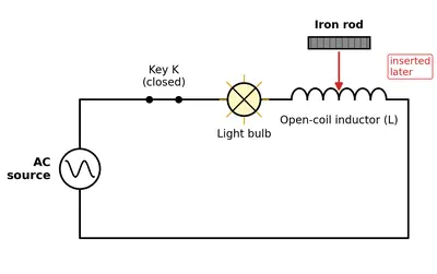
A light bulb and an open coil inductor are connected to an ac source through a key as shown in Fig. 7.9.

The switch is closed and after sometime, an iron rod is inserted into the interior of the inductor. The glow of the light bulb (a) increases; (b) decreases; (c) is unchanged, as the iron rod is inserted. Give your answer with reasons.

Fig. 7.9
Fig. 7.9

Solution

The light bulb (which behaves as a resistor $$R$$) and the open coil inductor are in series across the ac source. The current in the circuit is

$$I = \dfrac{V}{Z}, \qquad Z = \sqrt{R^2 + X_L^2}, \qquad X_L = \omega L$$

An open coil (air-core) inductor has a relatively small inductance $$L$$. When an iron rod is inserted into its interior, the iron — being ferromagnetic — greatly increases the magnetic flux linked with the coil, so the inductance $$L$$ increases substantially.

A larger $$L$$ gives a larger inductive reactance $$X_L = \omega L$$, and hence a larger impedance $$Z$$. Since $$I = V/Z$$, the current in the circuit decreases.

The power delivered to the bulb is $$P = I^2 R$$; with a smaller current the bulb receives less power and its glow falls.

Therefore the glow of the bulb decreases — option (b).

Answer

(b) The glow decreases. Inserting the iron rod raises the inductance $$L$$, hence $$X_L$$ and the impedance $$Z$$ rise, the current $$I = V/Z$$ falls, and so does the power $$I^2R$$ delivered to the bulb.

Example 7.6 A resistor of $$200 \, \Omega$$ and a capacitor of $$15.0 \, \mu\mathrm{F}$$ are connected in series to a 220 V, 50 Hz ac source. (a) Calculate the current in the circuit; (b) Calculate the voltage (rms) across the resistor and the capacitor. Is the algebraic sum of these voltages more than the source voltage? If yes, resolve the paradox.

Solution

Given data

  • Resistance: $$R = 200\,\Omega$$
  • Capacitance: $$C = 15.0\,\mu\mathrm{F}=15.0\times10^{-6}\,\mathrm{F}$$
  • Supply voltage (rms): $$V = 220\,\mathrm{V}$$
  • Frequency: $$f = 50\,\mathrm{Hz}$$

Angular frequency

$$\omega = 2\pi f = 2\pi(50) = 100\pi \;\mathrm{rad\,s^{-1}} \approx 3.14\times10^{2}\,\mathrm{rad\,s^{-1}}$$

Capacitive reactance

$$X_{C}=\frac{1}{\omega C}=\frac{1}{(3.14\times10^{2})(15.0\times10^{-6})} =2.12\times10^{2}\,\Omega \;(\text{about } 212\,\Omega)$$

Impedance of the series RC circuit

Magnitude: $$Z = \sqrt{R^{2}+X_{C}^{2}} =\sqrt{(200)^{2}+(212)^{2}} =\sqrt{40000+44944} =\sqrt{84944} \approx 2.92\times10^{2}\,\Omega\;(291.5\,\Omega)$$

(a) rms current

$$I = \frac{V}{Z}=\frac{220\,\mathrm{V}}{291.5\,\Omega}=0.755\,\mathrm{A}$$

(b) rms voltages across the elements

  • Across the resistor: $$V_{R}=IR=(0.755\,\mathrm{A})(200\,\Omega)=1.51\times10^{2}\,\mathrm{V} \;(151\,\mathrm{V})$$
  • Across the capacitor: $$V_{C}=IX_{C}=(0.755\,\mathrm{A})(212\,\Omega)=1.60\times10^{2}\,\mathrm{V} \;(160\,\mathrm{V})$$

The simple algebraic sum of the magnitudes is

$$V_{R}+V_{C}=151\,\mathrm{V}+160\,\mathrm{V}=311\,\mathrm{V}>V_{\text{source}}$$

Why is it larger than 220 V?

The two component voltages are not in phase. In a series RC circuit the resistor voltage $$V_{R}$$ is in phase with the current, while the capacitor voltage $$V_{C}$$ lags the current by $$90^{\circ}$$. Therefore they must be added vectorially (phasor addition), not algebraically. The right-angled triangle formed by $$V_{R}$$ (along the current) and $$V_{C}$$ (lagging by $$90^{\circ}$$) has a hypotenuse

$$V=\sqrt{V_{R}^{2}+V_{C}^{2}}\approx\sqrt{(151)^{2}+(160)^{2}}\;\mathrm{V}\approx220\,\mathrm{V},$$

which exactly equals the applied rms voltage. Thus there is no contradiction.

Answer

(a) $$I_{\text{rms}} \approx 0.76\,\mathrm{A}$$
(b) $$V_R \approx 151\,\mathrm{V},\; V_C \approx 160\,\mathrm{V}$$.
Their simple sum (311 V) exceeds 220 V because the two voltages are out of phase; the vector (phasor) sum equals the source voltage, resolving the apparent paradox.

Example 7.7

(a) For circuits used for transporting electric power, a low power factor implies large power loss in transmission. Explain.

(b) Power factor can often be improved by the use of a capacitor of appropriate capacitance in the circuit. Explain.

Solution

Background formulae for an a.c. line

  • Instantaneous voltage and current: $$v = V_0 \sin \omega t, \;\; i = I_0 \sin (\omega t - \phi)$$
  • r.m.s. values: $$V = V_0/\sqrt 2, \; I = I_0/\sqrt 2$$
  • Average (real) power delivered: $$P = VI \cos \phi$$. Here $$\cos\phi$$ is called the power factor.

When electricity is sent from a generating station (source) to a consumer (load), the two relevant quantities are

  • the load current $$I$$ which the station must supply so that the consumer receives the desired real power $$P$$,
  • the line (ohmic) loss in the transmission resistance $$R$$: $$P_{\text{loss}} = I^{2} R$$.

(a) Why a low power factor implies large power loss

Suppose the consumer needs a fixed real power $$P$$ and the r.m.s. transmission voltage is fixed at $$V$$ (this is normally the case for a given line rating).

From the power relation $$P = VI \cos \phi$$, the required line current is

$$I = \dfrac{P}{V \cos \phi}.$$

This current has to pass through the (unavoidable) resistance $$R$$ of the transmission line. The ohmic loss is therefore

$$P_{\text{loss}} = I^{2} R = \left( \dfrac{P}{V \cos \phi} \right)^{\!2} R = \dfrac{P^{2} R}{V^{2} \cos^{2} \phi}.$$

Hence, for fixed $$P,\,V,\,R$$,

$$P_{\text{loss}} \propto \dfrac{1}{\cos^{2} \phi}.$$

If the power factor is low (i.e. $$\cos \phi \ll 1$$), the denominator $$\cos^{2}\phi$$ becomes small, the required current $$I$$ becomes large, and the resistive loss $$P_{\text{loss}}$$ increases quadratically. Therefore, a low power factor leads directly to a large power loss during transmission.

(b) How a capacitor improves the power factor

Most industrial and commercial loads (induction motors, transformers, fluorescent lamps, etc.) are dominantly inductive. An inductive reactance $$X_L = \omega L$$ makes the current lag behind the voltage by an angle $$\phi_L$$, so the power factor $$\cos \phi_L$$ is less than unity.

Attach a capacitor of reactance $$X_C = \dfrac{1}{\omega C}$$ either in series with the load (for simple single-device circuits) or, more usually, in parallel (shunt) across the load (power-factor correction banks used in distribution networks):

  • The capacitor current leads the voltage by $$90^{\circ}$$, exactly opposite to the lag introduced by the inductor.
  • Because the two reactive currents are out of phase, they partially cancel each other.

Quantitatively, if the inductive and capacitive reactances appear in series with a resistance $$R$$, the net reactance becomes

$$X = X_L - X_C = \omega L - \dfrac{1}{\omega C}.$$

By choosing $$C$$ so that $$X_C \approx X_L$$, we can make $$X \to 0$$. The impedance $$Z$$ then approaches the pure resistance $$R$$:

$$Z = \sqrt{R^{2}+X^{2}} \longrightarrow R, \qquad \phi = \tan^{-1}\!\left(\dfrac{X}{R}\right) \longrightarrow 0.$$

Therefore $$\cos \phi \longrightarrow 1$$ and the power factor is said to be improved (brought as close to unity as economically feasible). With a higher power factor:

  • The load draws a smaller current for the same real power.
  • Transmission losses $$P_{\text{loss}} = I^{2}R$$ fall accordingly.

Capacitor banks are inexpensive, have negligible energy dissipation, and supply only the necessary leading reactive power. Hence they are the standard devices for power-factor correction in a.c. power systems.

Answer

(a) Because real transmitted power is $$P = VI\cos\phi$$, the required line current is $$I = P/(V\cos\phi)$$. The resistive loss in the line, $$P_{\text{loss}} = I^{2}R = P^{2}R/(V^{2}\cos^{2}\phi)$$, therefore increases as $$1/\cos^{2}\phi$$. A low power factor (small $$\cos\phi$$) means a larger current and hence a much larger power loss.

(b) Inductive loads make the current lag; a shunt or series capacitor supplies a leading current. Choosing the capacitance so that its reactance nearly cancels the inductive reactance reduces the net reactance, decreases the phase angle $$\phi$$, and raises $$\cos\phi$$ toward unity. Thus a capacitor improves the power factor and cuts transmission losses.

Example 7.8 A sinusoidal voltage of peak value 283 V and frequency 50 Hz is applied to a series $$LCR$$ circuit in which $$R = 3 \, \Omega$$, $$L = 25.48 \, \mathrm{mH}$$, and $$C = 796 \, \mu\mathrm{F}$$. Find (a) the impedance of the circuit; (b) the phase difference between the voltage across the source and the current; (c) the power dissipated in the circuit; and (d) the power factor.

Solution

Given data
Peak (maximum) source voltage: $$V_{m}=283\;\text{V}$$   Frequency: $$f=50\;\text{Hz}$$
Resistance: $$R=3\;\Omega$$   Inductance: $$L = 25.48\,\text{mH}=0.02548\,\text{H}$$
Capacitance: $$C = 796\,\mu\text{F}=7.96\times10^{-4}\,\text{F}$$

The root-mean-square (r.m.s.) source voltage is
$$V_{\text{rms}}=\frac{V_{m}}{\sqrt 2}=\frac{283}{\sqrt 2}\;\text{V}\approx 200\;\text{V}$$

The angular frequency is
$$\omega = 2\pi f = 2\pi(50) = 100\pi\;\text{rad s}^{-1}\approx 314.16\;\text{rad s}^{-1}$$

Reactances
Inductive reactance:
$$X_{L}=\omega L = 314.16\times0.02548\;\Omega \approx 8.00\;\Omega$$
Capacitive reactance:
$$X_{C}=\frac{1}{\omega C}=\frac{1}{314.16\times7.96\times10^{-4}}\;\Omega\approx 4.00\;\Omega$$

(a) Impedance
The net reactance: $$X = X_{L}-X_{C} = 8.00-4.00 = 4.00\;\Omega$$
$$Z = \sqrt{R^{2}+X^{2}} = \sqrt{3^{2}+4^{2}}\;\Omega \approx 5.0\;\Omega$$

(b) Phase difference
$$\tan\phi = \frac{X}{R}=\frac{4.00}{3}=1.33$$
$$\phi \approx \arctan(1.33) \approx 53^{\circ}$$
(because $$X_{L}>X_{C}$$, the current lags the source voltage by this angle).

(c) Power dissipated
r.m.s. current:
$$I_{\text{rms}} = \frac{V_{\text{rms}}}{Z}=\frac{200}{5.0}\;\text{A}\approx 40\;\text{A}$$
Power in a series $$LCR$$ circuit is lost only in $$R$$:
$$P = I_{\text{rms}}^{2}R = (40\,\text{A})^{2}(3\,\Omega) \approx 4.8\times10^{3}\,\text{W} = 4.8\,\text{kW}$$

(d) Power factor
$$\cos\phi = \frac{R}{Z}=\frac{3}{5.0}\approx 0.60$$ (lagging).

Answer

(a) Impedance $$Z \approx 5.0\;\Omega$$
(b) Phase difference $$\phi \approx 53^{\circ}\;\text{(current lags)}$$
(c) Power dissipated $$P \approx 4.8\,\text{kW}$$
(d) Power factor $$\cos\phi \approx 0.60\;\text{(lagging)}$$

Example 7.9 Suppose the frequency of the source in the previous example can be varied. (a) What is the frequency of the source at which resonance occurs? (b) Calculate the impedance, the current, and the power dissipated at the resonant condition.

Solution

Data taken from the previous example
Series $$RLC$$ circuit with the values

  • Resistance  $$R = 400\,\Omega$$
  • Inductance  $$L = 0.30\,\text{H}$$
  • Capacitance  $$C = 40\,\mu\text{F}=40\times10^{-6}\,\text{F}$$
  • Applied (r.m.s.) voltage  $$V_{\text{rms}} = 220\,\text{V}$$

(a) Resonant frequency
At resonance the inductive and capacitive reactances cancel: $$\omega_0L = \dfrac1{\omega_0C} \;\Rightarrow\; \omega_0 = \dfrac1{\sqrt{LC}}$$
Numerically, $$LC = 0.30\times40\times10^{-6}=1.2\times10^{-5}\;\text{H F}$$
$$\sqrt{LC}=\sqrt{1.2\times10^{-5}} = 3.464\times10^{-3}$$
$$\omega_0 = \dfrac{1}{3.464\times10^{-3}} = 2.887\times10^{2}\,\text{rad\,s}^{-1}$$
$$f_0 = \dfrac{\omega_0}{2\pi}=\dfrac{2.887\times10^{2}}{2\pi}=45.9\,\text{Hz}\;(\text{≈ }46\,\text{Hz})$$

(b) Impedance, current and power at resonance
Because the net reactance is zero, the impedance is purely resistive:
$$Z_0 = R = 400\,\Omega$$
The r.m.s. current is therefore
$$I_0 = \dfrac{V_{\text{rms}}}{Z_0}=\dfrac{220}{400}=0.55\,\text{A}$$
The phase angle is zero, so the power factor is unity and the average power dissipated is
$$P_0 = V_{\text{rms}} I_{\text{rms}}\cos\phi = 220\times0.55\times1 = 1.21\times10^{2}\,\text{W}\;(=121\,\text{W})$$

Result
(a) $$f_0\approx46\,\text{Hz}$$
(b) At resonance  $$Z = 400\,\Omega,\; I = 0.55\,\text{A},\; P = 121\,\text{W}.$$

Answer

(a) Resonance occurs at about $$f_0 \approx 46\,\text{Hz}$$.
(b) At resonance:  $$Z = 400\,\Omega,\; I = 0.55\,\text{A},\; P = 1.2\times10^{2}\,\text{W}\;(\approx 121\,\text{W}).$$

Example 7.10 At an airport, a person is made to walk through the doorway of a metal detector, for security reasons. If she/he is carrying anything made of metal, the metal detector emits a sound. On what principle does this detector work?

Solution

Goal. Explain the physical principle behind the walk-through metal detector used at airports.

1  Construction of the detector

  • The doorway houses an induction coil that forms the inductive element $$L$$ of a tuned RLC oscillator.
  • A small capacitor $$C$$ is connected so that the coil and the capacitor constitute a tank circuit having natural (angular) resonant frequency
    $$\omega_0 = \tfrac{1}{\sqrt{LC}}.$$
  • The circuit is kept in steady oscillation by a low-power transistor amplifier; as long as the electrical parameters remain unchanged, the amplitude of the alternating magnetic field is constant.

2  Basic physics involved

  1. Faraday’s law of electromagnetic induction:
    Whenever the magnetic flux $$\Phi_B$$ linked with a conducting loop changes, an emf
    $$\mathcal{E} = -\dfrac{d\Phi_B}{dt}$$ gets induced.
  2. Eddy currents: In a bulk metallic piece (not a single wire) these induced emf’s circulate as closed loops of current inside the body; they are called eddy currents.
  3. Lenz’s law: The eddy currents set up their own magnetic field that opposes the change responsible for them. Hence they always try to weaken the original alternating field produced by the coil.

3  What happens when a person carrying metal walks in

  • The metal article is suddenly exposed to the coil’s alternating magnetic field; the flux through it becomes time-varying.
  • By Faraday’s law, appreciable eddy currents are induced in the object. These currents behave, from the coil’s point of view, as an additional load.
  • Electrically this load can be represented by an extra resistance $$R_e$$ and a small change in effective inductance $$\Delta L$$ coupled to the original circuit.

4  Effect on the tuned circuit

Before the metal arrives, the impedance of the series RLC is

$$Z_0 = \sqrt{R^2 + (\omega L - \tfrac{1}{\omega C})^2}.$$

At resonance $$\omega = \omega_0$$, so $$Z_0 = R$$ and the oscillating current reaches a large, constant amplitude.

  • The appearance of $$R_e$$ raises the total resistance to $$R' = R + R_e$$.
  • The small change $$\Delta L$$ shifts the resonant frequency to $$\omega' \approx \omega_0\left(1 - \tfrac{\Delta L}{2L}\right).$$
  • Consequently the circuit is instantly driven off resonance and its current amplitude falls sharply.

5  Detection and alarm

An envelope detector continuously monitors the oscillator’s amplitude. The moment the amplitude drops below a preset threshold, the electronic circuit actuates a buzzer or beeper. Thus the sound is heard only when a conducting (metallic) object, capable of supporting eddy currents, is carried through the doorway.

6  Principle stated concisely

The metal detector operates on the principle of electromagnetic induction (Faraday’s law) and the eddy currents it produces in nearby conductors. The eddy currents load and detune a resonant AC circuit; the resulting change in amplitude/frequency is sensed and converted into an audible signal.

Answer

It relies on electromagnetic induction: the doorway coil carries an AC current. When a metal object enters, the alternating magnetic field induces eddy currents in the metal; these currents change the coil’s effective inductance and resistance, detuning the LC oscillator. The sudden drop in the oscillator’s amplitude is detected and triggers the alarm.

Exercises

7.1 A $$100 \, \Omega$$ resistor is connected to a 220 V, 50 Hz ac supply.

(a) What is the rms value of current in the circuit?

Solution

The given alternating source is specified by its root–mean–square (rms) voltage

$$V_{\text{rms}} = 220\;\text{V}$$

For a purely resistive circuit, Ohm’s law holds for the rms values:

$$I_{\text{rms}} = \dfrac{V_{\text{rms}}}{R}$$

Substituting the resistance $$R = 100\,\Omega$$,

$$I_{\text{rms}} = \dfrac{220\,\text{V}}{100\,\Omega} = 2.2\,\text{A}$$

Answer

$$I_{\text{rms}} = 2.2\,\text{A}$$

(b) What is the net power consumed over a full cycle?

Solution

For a resistor, the average (or net) power consumed over one complete cycle is

$$P = V_{\text{rms}} I_{\text{rms}}$$

The phase angle between voltage and current is zero, so $$\cos\phi = 1$$ is already included in this expression.

Using the values found and given,

$$P = (220\,\text{V})(2.2\,\text{A}) = 484\,\text{W}$$

One may also verify with $$P = I_{\text{rms}}^{2} R$$:

$$P = (2.2\,\text{A})^{2}(100\,\Omega) = 4.84\times 10^{2}\,\text{W} = 484\,\text{W}$$

Hence the resistor continuously converts 484 W of electrical energy into heat each cycle, so the net (average) power per cycle is 484 W.

Answer

$$P_{\text{avg}} = 484\,\text{W}$$

7.2

(a) The peak voltage of an ac supply is 300 V. What is the rms voltage?

Solution

The instantaneous alternating emf can be written as $$V(t)=V_0\sin\omega t$$ where $$V_0$$ is the peak (maximum) value.

For a purely sinusoidal waveform the root-mean-square value is related to the peak value by

$$V_{\mathrm{rms}}=\dfrac{V_0}{\sqrt 2}\,.$$

Given $$V_0 = 300\;\mathrm{V}$$, substitute:

$$V_{\mathrm{rms}} = \dfrac{300\,\mathrm{V}}{\sqrt 2} = 300 \times \dfrac{1}{1.414}\,\mathrm{V}\approx 2.12\times10^{2}\,\mathrm{V}.$$

Therefore $$V_{\mathrm{rms}}\approx 212\,\mathrm{V}. $$

Answer

$$V_{\mathrm{rms}}\approx 212\,\mathrm{V}$$

(b) The rms value of current in an ac circuit is 10 A. What is the peak current?

Solution

For a sinusoidal current $$I(t)=I_0\sin\omega t$$, the rms and peak values obey

$$I_{\mathrm{rms}}=\dfrac{I_0}{\sqrt 2}\;\;\text{or}\;\;I_0 = I_{\mathrm{rms}}\sqrt 2.$$

Given $$I_{\mathrm{rms}} = 10\,\mathrm{A}$$:

$$I_0 = 10\,\mathrm{A}\times\sqrt 2 = 10\times1.414\,\mathrm{A}\approx 14.14\,\mathrm{A}.$$

Hence $$I_0\approx 14.1\,\mathrm{A}. $$

Answer

$$I_0\approx 14.1\,\mathrm{A}$$

7.3 A 44 mH inductor is connected to 220 V, 50 Hz ac supply. Determine the rms value of the current in the circuit.

Solution

Given data

  • Inductance: $$L = 44\,\text{mH} = 44 \times 10^{-3}\,\text{H}$$
  • Supply voltage (rms): $$V_{\text{rms}} = 220\,\text{V}$$
  • Frequency: $$f = 50\,\text{Hz}$$

Step 1: Calculate the inductive reactance

The reactance of a pure inductor is $$X_L = 2\pi f L$$.

Substituting the given values,

$$\begin{aligned}X_L &= 2\pi \times 50\,\text{Hz} \times 44 \times 10^{-3}\,\text{H}\\[2pt] &= 2\pi \times 50 \times 0.044\\[2pt] &= 6.283 \times 50 \times 0.044\\[2pt] &= 13.4\,\Omega\;(\text{approximately}).\end{aligned}$$

Step 2: Find the rms current

For a purely inductive circuit the rms current is given by $$I_{\text{rms}} = \dfrac{V_{\text{rms}}}{X_L}$$.

Hence,

$$I_{\text{rms}} = \dfrac{220\,\text{V}}{13.4\,\Omega} \approx 16\,\text{A}.$$

Result

The rms value of the current in the circuit is about $$16\,\text{A}$$.

Answer

$$I_{\text{rms}} \approx 16\,\text{A}$$

7.4 A $$60 \, \mu\mathrm{F}$$ capacitor is connected to a 110 V, 60 Hz ac supply. Determine the rms value of the current in the circuit.

Solution

The circuit contains only a capacitor, therefore the opposition to the alternating current is the capacitive reactance $$X_C$$.

Given values:
$$C = 60\,\mu\mathrm{F} = 60 \times 10^{-6}\;\mathrm{F}$$
$$f = 60\;\mathrm{Hz}$$
$$V_{\mathrm{rms}} = 110\;\mathrm{V}$$

1. Calculate the capacitive reactance:

$$X_C = \frac{1}{2\pi f C}$$

Substituting the numbers,
$$X_C = \frac{1}{2\pi \,(60)\,(60 \times 10^{-6})}$$

First evaluate the denominator step by step:
$$2\pi = 6.2832$$
$$6.2832 \times 60 = 376.992$$
$$376.992 \times 60 \times 10^{-6} = 376.992 \times 0.000060 = 0.02261952$$

Hence,
$$X_C = \frac{1}{0.02261952}\;\Omega \approx 44.2\;\Omega$$

2. The r.m.s. current in a purely capacitive circuit is given by

$$I_{\mathrm{rms}} = \frac{V_{\mathrm{rms}}}{X_C}$$

Therefore,
$$I_{\mathrm{rms}} = \frac{110\;\mathrm{V}}{44.2\;\Omega} \approx 2.49\;\mathrm{A}$$

Rounding to two significant figures,

$$I_{\mathrm{rms}} \approx 2.5\;\mathrm{A}$$

Answer

$$I_{\mathrm{rms}} \approx 2.5\,\mathrm{A}$$

7.5 In Exercises 7.3 and 7.4, what is the net power absorbed by each circuit over a complete cycle. Explain your answer.

Solution

Background (Exercises 7.3 and 7.4)

  • Ex. 7.3 : a pure inductor $$L = 25\,\mathrm{mH}$$ is connected to a $$V_{\mathrm{rms}} = 220\,\mathrm{V}$$, $$f = 50\,\mathrm{Hz}$$ source.
  • Ex. 7.4 : a pure capacitor $$C = 50\,\mu\mathrm{F}$$ is connected to a $$V_{\mathrm{rms}} = 200\,\mathrm{V}$$, $$f = 50\,\mathrm{Hz}$$ source.

For an a.c. circuit the average (net) power over one complete cycle is

$$P_{\text{avg}} = V_{\mathrm{rms}} I_{\mathrm{rms}} \cos\varphi,$$

where $$\varphi$$ is the phase difference between the voltage and the current.

1. Pure inductor (Exercise 7.3)

The current lags the voltage by $$90^\circ$$: $$\varphi = 90^\circ$$.

Hence $$\cos\varphi = \cos 90^\circ = 0 \;\Rightarrow\; P_{\text{avg}} = 0.$$

(The source alternately stores energy in the magnetic field of the inductor and then gets it back; the net energy supplied in one cycle is therefore zero.)

2. Pure capacitor (Exercise 7.4)

The current leads the voltage by $$90^\circ$$: $$\varphi = -90^\circ$$ (or $$+90^\circ$$ in magnitude).

Again $$\cos\varphi = \cos 90^\circ = 0 \;\Rightarrow\; P_{\text{avg}} = 0.$$

(Here energy is cyclically stored in and returned from the electric field of the capacitor, so no net energy is consumed.)

Conclusion

For both circuits the average power absorbed in a complete cycle is zero because the phase difference between current and voltage is $$90^\circ$$, making the power factor $$\cos\varphi$$ equal to zero.

Answer

For both the pure-inductor circuit of Exercise 7.3 and the pure-capacitor circuit of Exercise 7.4 the phase difference between voltage and current is $$90^\circ$$, so $$\cos\varphi = 0$$. Hence the average (net) power absorbed in one complete cycle is

$$P_{\text{avg}} = V_{\mathrm{rms}} I_{\mathrm{rms}} \cos\varphi = 0.$$

7.6 A charged $$30 \, \mu\mathrm{F}$$ capacitor is connected to a 27 mH inductor. What is the angular frequency of free oscillations of the circuit?

Solution

The circuit forms an ideal, loss‑free L C oscillator.

Convert the given components to SI units:
$$C = 30\,\mu\mathrm{F} = 30 \times 10^{-6}\,\mathrm{F}$$
$$L = 27\,\mathrm{mH} = 27 \times 10^{-3}\,\mathrm{H}$$

For free oscillations the angular frequency is

$$\omega = \dfrac{1}{\sqrt{L\,C}}$$

First evaluate the product $$L C$$:

$$L C = \left(27 \times 10^{-3}\right)\left(30 \times 10^{-6}\right)\,\mathrm{H\,F}$$ $$= 810 \times 10^{-9}\,\mathrm{s^{2}}$$ $$= 8.10 \times 10^{-7}\,\mathrm{s^{2}}$$

Take the square root:

$$\sqrt{L C} = \sqrt{8.10 \times 10^{-7}}$$ $$= \sqrt{8.10}\,\sqrt{10^{-7}}$$ $$\approx 2.85 \times 3.16 \times 10^{-4}\,\mathrm{s}$$ $$\approx 9.0 \times 10^{-4}\,\mathrm{s}$$

Finally,

$$\omega = \dfrac{1}{9.0 \times 10^{-4}}\,\mathrm{rad\,s^{-1}} \approx 1.1 \times 10^{3}\,\mathrm{rad\,s^{-1}}$$

Answer

$$\boxed{\omega \approx 1.1 \times 10^{3}\,\mathrm{rad\,s^{-1}}}$$

7.7 A series $$LCR$$ circuit with $$R = 20 \, \Omega$$, $$L = 1.5 \, \mathrm{H}$$ and $$C = 35 \, \mu\mathrm{F}$$ is connected to a variable-frequency 200 V ac supply. When the frequency of the supply equals the natural frequency of the circuit, what is the average power transferred to the circuit in one complete cycle?

Solution

Given data

  • Resistance: $$R = 20\,\Omega$$
  • Inductance: $$L = 1.5\,\mathrm{H}$$
  • Capacitance: $$C = 35\,\mu\mathrm{F} = 35 \times 10^{-6}\,\mathrm{F}$$
  • Applied ac (r.m.s.) voltage: $$V = 200\,\mathrm{V}$$

The circuit is operated at its natural (resonant) frequency.

Step 1 : Impedance at resonance

For a series $$LCR$$ circuit the impedance is $$Z = \sqrt{R^{2} + \left(\omega L - \dfrac{1}{\omega C}\right)^2}$$.

At resonance $$\omega = \omega_{0} = \dfrac{1}{\sqrt{LC}}$$, so $$\omega_{0}L = \dfrac{1}{\omega_{0}C}$$ and therefore $$Z = R$$ (purely resistive).

Step 2 : r.m.s. current in the circuit

Because $$Z = R$$, the r.m.s. current amplitude is

$$I = \dfrac{V}{R} = \dfrac{200\,\mathrm{V}}{20\,\Omega} = 10\,\mathrm{A}$$.

Step 3 : Average power over one complete cycle

The average power absorbed by an a.c. circuit is

$$P_{\text{avg}} = V I \cos \phi,$$

where $$\phi$$ is the phase angle between current and voltage. At resonance $$\phi = 0^{\circ}$$, hence $$\cos \phi = 1$$.

Thus,

$$P_{\text{avg}} = V I = (200\,\mathrm{V})(10\,\mathrm{A}) = 2.0 \times 10^{3}\,\mathrm{W}.$$

Alternative form :

$$P_{\text{avg}} = \dfrac{V^{2}}{R} = \dfrac{(200\,\mathrm{V})^{2}}{20\,\Omega} = 2.0 \times 10^{3}\,\mathrm{W},$$ identical to the value obtained above.

Hence, the average power delivered to the circuit in one complete cycle is $$2.0\,\text{kW}$$.

Answer

Average power transferred at resonance:
$$P_{\text{avg}} = \dfrac{V^{2}}{R} = \dfrac{(200\,\text{V})^{2}}{20\,\Omega} = 2.0 \times 10^{3}\,\text{W}.$$

7.8

Figure 7.17 shows a series $$LCR$$ circuit connected to a variable frequency 230 V source. $$L = 5.0 \, \mathrm{H}$$, $$C = 80 \, \mu\mathrm{F}$$, $$R = 40 \, \Omega$$.

Figure 7.17
Figure 7.17

(a) Determine the source frequency which drives the circuit in resonance.

Solution

The series LCR circuit is in electrical resonance when its inductive reactance equals its capacitive reactance, i.e. $$X_L = X_C$$.
For resonance the angular frequency is

$$\omega_0 = \frac{1}{\sqrt{LC}}$$

Given  $$L = 5.0\;\mathrm{H}$$,  $$C = 80\;\mu\mathrm{F} = 80\times10^{-6}\;\mathrm{F}$$, therefore

$$LC = 5.0\,(80\times10^{-6}) = 4.0\times10^{-4}\;\mathrm{H\,F}$$

$$\sqrt{LC} = \sqrt{4.0\times10^{-4}} = 2.0\times10^{-2}$$

$$\omega_0 = \frac{1}{2.0\times10^{-2}} = 50\;\mathrm{rad\,s^{-1}}$$

The linear (ordinary) resonant frequency is

$$f_0 = \frac{\omega_0}{2\pi} = \frac{50}{2\pi}\;\mathrm{Hz} = \frac{25}{\pi}\;\mathrm{Hz} \approx 7.96\;\mathrm{Hz}\;\,(\text{$\sim$}8\;\mathrm{Hz})$$

Answer

$$f_0 \approx 8\;\mathrm{Hz}$$ (\(\omega_0 = 50\;\mathrm{rad\,s^{-1}}\))

(b) Obtain the impedance of the circuit and the amplitude of current at the resonating frequency.

Solution

At resonance $$X_L = X_C$$, hence the impedance reduces to

$$Z = R = 40\;\Omega$$

The source provides an rms voltage $$V_{\text{rms}} = 230\;\mathrm{V}$$, therefore the rms current is

$$I_{\text{rms}} = \frac{V_{\text{rms}}}{Z} = \frac{230}{40} = 5.75\;\mathrm{A}$$

The peak (amplitude) value of the current is

$$I_0 = \sqrt2\,I_{\text{rms}} = 1.414\,(5.75) \approx 8.1\;\mathrm{A}$$

Answer

$$Z = 40\;\Omega$$,  $$I_{\text{rms}} = 5.75\;\mathrm{A}$$ (peak value $$I_0 \approx 8.1\;\mathrm{A}$$)

(c) Determine the rms potential drops across the three elements of the circuit. Show that the potential drop across the $$LC$$ combination is zero at the resonating frequency.

Solution

Using the rms current found above, $$I_{\text{rms}} = 5.75\;\mathrm{A}$$.

(i) Resistor

$$V_R = I_{\text{rms}}R = 5.75\times40 = 230\;\mathrm{V}$$

(ii) Inductor

The inductive reactance at resonance is

$$X_L = \omega_0 L = 50\,(5.0) = 250\;\Omega$$

$$V_L = I_{\text{rms}}X_L = 5.75\times250 = 1.44\times10^{3}\;\mathrm{V}$$

(iii) Capacitor

$$X_C = \frac{1}{\omega_0C} = \frac{1}{50\,(80\times10^{-6})} = 250\;\Omega$$

$$V_C = I_{\text{rms}}X_C = 5.75\times250 = 1.44\times10^{3}\;\mathrm{V}$$

The voltage across the inductor leads the current by $$90^{\circ}$$ while that across the capacitor lags by $$90^{\circ}$$, hence

$$\vec V_L + \vec V_C = 1.44\,\mathrm{kV}\,(+90^{\circ}) + 1.44\,\mathrm{kV}\,(-90^{\circ}) = 0$$

Thus the net potential difference across the combined $$LC$$ branch is zero, as required for resonance.

Answer

$$V_R = 230\;\mathrm{V}\;\text{(rms)},\quad V_L = 1.44\,\mathrm{kV}\;\text{(rms)},\quad V_C = 1.44\,\mathrm{kV}\;\text{(rms)},$$ and $$V_L + V_C = 0$$ at resonance.

NCERT Solutions for Class 12
Maths
NCERT Solutions for Class 12 Maths
Chapter-wise step-by-step
solutions with explanations
explore solutions Maths bg
Physics
NCERT Solutions for Class 12 Physics
Chapter-wise step-by-step
solutions with explanations
explore solutions Physics bg
Chemistry
NCERT Solutions for Class 12 Chemistry
Chapter-wise step-by-step
solutions with explanations
explore solutions Chemistry bg

Frequently Asked Questions

50,000+ JEE Students Trusted Our Score Calculator

Predict your JEE Main percentile, rank & performance in seconds