Join WhatsApp Icon JEE WhatsApp Group
NCERT Solutions for Class 12 Physics

Chapter 6: Electromagnetic Induction

Download Solutions PDF
Daily JEE Updates, Tips & Important Alerts
Join 30,000+ students and stay updated with JEE notifications and preparation insights.
Join Now!
Free PDF
Complete NCERT Solution PDF for Chapter 6: Electromagnetic Induction

NCERT Solutions For Class 12 Physics Chapter 6 Electromagnetic Induction helps students understand how changing magnetic fields can produce electric current. The page provides complete NCERT Solutions that explain important concepts such as Faraday’s laws, Lenz’s law, magnetic flux, induced emf, and applications of electromagnetic induction. NCERT Solutions For Class 12 Physics simplify these concepts through detailed explanations, diagrams, and numerical problem-solving methods. The chapter introduces one of the most important principles behind electrical generators and modern technologies. These solutions help students strengthen their understanding of electromagnetic phenomena and improve numerical accuracy. Students can use the chapter PDF for revision, practice, and exam preparation. The clear explanations make electromagnetic induction concepts easier to learn and apply.
Download Solutions PDF

Examples 6.1-6.10

Example 6.1 Consider Experiment 6.2. (a) What would you do to obtain a large deflection of the galvanometer? (b) How would you demonstrate the presence of an induced current in the absence of a galvanometer?

(a) What would you do to obtain a large deflection of the galvanometer?

Solution

In Experiment 6.2, two coils $$C_1$$ and $$C_2$$ are placed close together. When the current in one coil is changed, the changing magnetic flux through the other coil induces an emf, and the galvanometer deflects. The deflection is proportional to the induced emf, which equals the rate of change of flux linkage $$N\dfrac{d\Phi_B}{dt}$$.

To obtain a large deflection, this rate of change of flux linkage must be made as large as possible. One or more of the following steps can be taken:

  • Place a rod of soft iron inside the coil $$C_2$$. The soft-iron core greatly increases the magnetic field and hence the flux linked with the coils.
  • Connect the coil to a powerful battery, so that a large current flows and produces a strong magnetic field.
  • Move the arrangement of the two coils rapidly towards the test coil $$C_1$$, so that the flux changes in a very short time, making $$\dfrac{d\Phi_B}{dt}$$ large.

Answer

Use a soft-iron core inside the coil, connect the coil to a powerful battery, and move the coils rapidly so the flux changes quickly.

(b) How would you demonstrate the presence of an induced current in the absence of a galvanometer?

Solution

The galvanometer is only a detector of the induced current. Its role can be played by any device that visibly responds to a current.

Replace the galvanometer by a small bulb, of the kind used in a small torch light. Now move the two coils rapidly relative to each other (or rapidly switch the current in the other coil on and off). The changing flux induces a current large enough to make the bulb glow. The glowing of the bulb demonstrates the presence of the induced current even though no galvanometer is used.

Answer

Replace the galvanometer with a small bulb; the induced current produced by the relative motion of the coils makes the bulb glow.

Example 6.2 A square loop of side $$10 \, \mathrm{cm}$$ and resistance $$0.5 \, \Omega$$ is placed vertically in the east-west plane. A uniform magnetic field of $$0.10 \, \mathrm{T}$$ is set up across the plane in the north-east direction. The magnetic field is decreased to zero in $$0.70 \, \mathrm{s}$$ at a steady rate. Determine the magnitudes of induced emf and current during this time-interval.

Solution

Given: side of square loop $$a = 10\,\mathrm{cm} = 0.10\,\mathrm{m}$$, resistance $$R = 0.5\,\Omega$$, magnetic field $$B = 0.10\,\mathrm{T}$$, time interval $$\Delta t = 0.70\,\mathrm{s}$$.

The loop lies in the vertical east-west plane, so its normal (area vector) points along the north-south direction. The field is directed in the north-east direction, so the angle between the field $$\mathbf{B}$$ and the area vector $$\mathbf{A}$$ is $$\theta = 45^\circ$$.

Area of the loop:

$$A = a^2 = (0.10)^2 = 1.0\times10^{-2}\,\mathrm{m^2}$$

Initial flux through the loop:

$$\Phi_i = BA\cos\theta = 0.10 \times 1.0\times10^{-2} \times \cos 45^\circ = \frac{0.10\times10^{-2}}{\sqrt{2}} = \frac{10^{-3}}{\sqrt{2}}\,\mathrm{Wb}$$

Final flux: the field is reduced to zero, so $$\Phi_f = 0$$.

Induced emf (magnitude) is the rate of change of flux:

$$\varepsilon = \left|\frac{\Delta\Phi}{\Delta t}\right| = \frac{|\Phi_f - \Phi_i|}{\Delta t} = \frac{10^{-3}/\sqrt{2}}{0.70} = \frac{10^{-3}}{1.414 \times 0.70}$$

$$\varepsilon \approx 1.0\times10^{-3}\,\mathrm{V} = 1.0\,\mathrm{mV}$$

Induced current (magnitude):

$$I = \frac{\varepsilon}{R} = \frac{1.0\times10^{-3}}{0.5} = 2.0\times10^{-3}\,\mathrm{A} = 2\,\mathrm{mA}$$

Note: The earth's magnetic field also produces a flux through the loop, but it is steady (does not change during the experiment) and hence induces no emf.

Answer

Induced emf $$\varepsilon \approx 1.0\,\mathrm{mV}$$ and induced current $$I = 2\,\mathrm{mA}$$.

Example 6.3 A circular coil of radius $$10 \, \mathrm{cm}$$, $$500$$ turns and resistance $$2 \, \Omega$$ is placed with its plane perpendicular to the horizontal component of the earth's magnetic field. It is rotated about its vertical diameter through $$180^\circ$$ in $$0.25 \, \mathrm{s}$$. Estimate the magnitudes of the emf and current induced in the coil. Horizontal component of the earth's magnetic field at the place is $$3.0 \times 10^{-5} \, \mathrm{T}$$.

Solution

Given: radius $$r = 10\,\mathrm{cm} = 0.10\,\mathrm{m}$$, number of turns $$N = 500$$, resistance $$R = 2\,\Omega$$, time of rotation $$\Delta t = 0.25\,\mathrm{s}$$, horizontal component of earth's field $$B = 3.0\times10^{-5}\,\mathrm{T}$$.

Area of the coil:

$$A = \pi r^2 = \pi (0.10)^2 = \pi\times10^{-2}\,\mathrm{m^2}$$

Initially the plane of the coil is perpendicular to the horizontal field, so its area vector is parallel to $$\mathbf{B}$$, i.e. $$\theta = 0^\circ$$.

Initial flux through the coil:

$$\Phi_i = BA\cos 0^\circ = 3.0\times10^{-5} \times \pi\times10^{-2} = 3\pi\times10^{-7}\,\mathrm{Wb}$$

After rotating through $$180^\circ$$ about the vertical diameter, the area vector is reversed, so $$\theta = 180^\circ$$.

Final flux:

$$\Phi_f = BA\cos 180^\circ = -3\pi\times10^{-7}\,\mathrm{Wb}$$

Change in flux:

$$|\Delta\Phi| = |\Phi_f - \Phi_i| = |-3\pi\times10^{-7} - 3\pi\times10^{-7}| = 6\pi\times10^{-7}\,\mathrm{Wb}$$

Induced emf:

$$\varepsilon = N\frac{|\Delta\Phi|}{\Delta t} = \frac{500 \times 6\pi\times10^{-7}}{0.25} \approx 3.8\times10^{-3}\,\mathrm{V}$$

Induced current:

$$I = \frac{\varepsilon}{R} = \frac{3.8\times10^{-3}}{2} = 1.9\times10^{-3}\,\mathrm{A}$$

Note: These are estimated (average) values; the instantaneous emf and current depend on the speed of rotation at each instant.

Answer

Induced emf $$\varepsilon \approx 3.8\times10^{-3}\,\mathrm{V}$$ and induced current $$I \approx 1.9\times10^{-3}\,\mathrm{A}$$.

Example 6.4

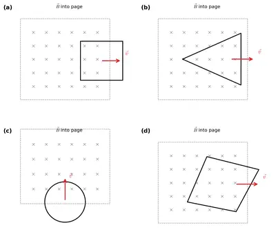
Figure 6.7 shows planar loops of different shapes moving out of or into a region of a magnetic field which is directed normal to the plane of the loop away from the reader. Determine the direction of induced current in each loop using Lenz's law.
Figure 6.7
Figure 6.7

Solution

The magnetic field is directed into the plane of the page (away from the reader), shown by the $$\times$$ symbols. By Lenz's law, the induced current always flows in a direction that opposes the change in magnetic flux that produces it.

(i) Rectangular loop abcd: The loop is moving into the field region, so the flux directed into the page through the loop is increasing. To oppose this increase, the induced current must produce a magnetic field out of the page inside the loop, i.e. it must flow anticlockwise. Hence the induced current flows along the path bcdab.

(ii) Triangular loop abc: The loop is moving out of the field region, so the flux into the page through it is decreasing. To oppose this decrease, the induced current must produce a field into the page inside the loop, i.e. it must flow clockwise. Hence the induced current flows along the path bacb.

(iii) Irregular loop abcd: This loop is also moving out of the field region, so the flux into the page through it is decreasing. To oppose this, the induced current must produce a field into the page inside the loop, i.e. it must flow clockwise. Hence the induced current flows along the path cdabc.

Important: There is no induced current in any loop while it lies completely inside or completely outside the field region, because then the flux through it is constant.

Answer

(i) Current along bcdab (anticlockwise); (ii) current along bacb (clockwise); (iii) current along cdabc (clockwise). No current when a loop is entirely inside or outside the field.

Example 6.5

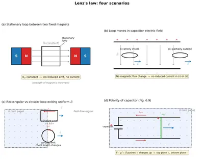
Determine the direction of induced current / polarity for each of the following situations using Lenz's law:
Fig. 6.8
Fig. 6.8

(a) A closed loop is held stationary in the magnetic field between the north and south poles of two permanent magnets held fixed. Can we hope to generate current in the loop by using very strong magnets?

Solution

No. The loop is held stationary in a steady magnetic field. An emf (and hence a current) is induced only when the magnetic flux linked with the loop changes with time.

Here, neither the loop nor the magnets move, and the field of the permanent magnets is constant. So the flux through the loop does not change, and no current is induced.

Using a stronger magnet only makes the (constant) flux larger; it does not make the flux change. Therefore, however strong the magnets may be, no current can be generated in the stationary loop.

Answer

No. A steady flux through a stationary loop induces no current, no matter how strong the magnets are.

(b) A closed loop moves normal to the constant electric field between the plates of a large capacitor. Is a current induced in the loop (i) when it is wholly inside the region between the capacitor plates (ii) when it is partially outside the plates of the capacitor? The electric field is normal to the plane of the loop.

Solution

No current is induced in either case — neither when the loop is wholly inside the capacitor nor when it is partially outside.

An induced emf (and current) arises only from a changing magnetic flux through the circuit. The space between the capacitor plates contains an electric field, not a magnetic field. A changing electric flux does not drive a conduction current around a closed conducting loop.

Hence, in case (i) and in case (ii), there is no induced current. The induced current cannot be produced by changing the electric flux linked with the loop.

Answer

No current is induced in either case; a changing electric flux does not induce a current in the loop.

(c) A rectangular loop and a circular loop are moving out of a uniform magnetic field region (Fig. 6.8) to a field-free region with a constant velocity $$\mathbf{v}$$. In which loop do you expect the induced emf to be constant during the passage out of the field region? The field is normal to the loops.

Solution

The induced emf is given by $$\varepsilon = B\dfrac{dA_{\text{in field}}}{dt}$$, where $$A_{\text{in field}}$$ is the area of the loop still inside the field region. Since $$B$$ and the speed $$v$$ are constant, the emf is constant only if the area leaves the field at a constant rate.

Rectangular loop: As it moves out at constant velocity, the length of the side cutting the field boundary stays the same, so the area inside the field decreases at a constant rate. Hence the induced emf is constant during the passage out.

Circular loop: As it moves out, the length of the chord at the field boundary keeps changing, so the area inside the field decreases at a non-uniform rate. Hence the induced emf is not constant — it varies during the passage out.

Therefore, the induced emf is expected to be constant only for the rectangular loop.

Answer

Only in the rectangular loop is the induced emf constant; for the circular loop it varies during the passage out.

(d) Predict the polarity of the capacitor in the situation described by Fig. 6.9.

Solution

In Fig. 6.9, two bar magnets are moved towards the coil from opposite sides, changing the magnetic flux linked with the coil and inducing an emf. The ends of the coil are connected to the plates A and B of the capacitor.

Applying Lenz's law to the coil, the induced current charges the capacitor in such a way that plate A becomes positive with respect to plate B.

Answer

Plate A is at positive polarity with respect to plate B.

Example 6.6

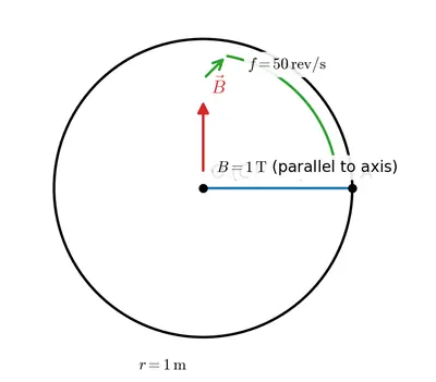
A metallic rod of $$1 \, \mathrm{m}$$ length is rotated with a frequency of $$50 \, \mathrm{rev/s}$$, with one end hinged at the centre and the other end at the circumference of a circular metallic ring of radius $$1 \, \mathrm{m}$$, about an axis passing through the centre and perpendicular to the plane of the ring (Fig. 6.11). A constant and uniform magnetic field of $$1 \, \mathrm{T}$$ parallel to the axis is present everywhere. What is the emf between the centre and the metallic ring?
Fig. 6.11
Fig. 6.11

Solution

Given: length of rod $$R = 1\,\mathrm{m}$$, frequency $$\nu = 50\,\mathrm{rev/s}$$, magnetic field $$B = 1\,\mathrm{T}$$ parallel to the axis of rotation.

Consider a small element of length $$dr$$ of the rod at a distance $$r$$ from the centre. It moves with speed $$v = \omega r$$ at right angles to $$B$$. The motional emf across this element is

$$d\varepsilon = B v\, dr = B\,\omega r\, dr$$

The total emf between the centre and the rim is obtained by integrating from $$r=0$$ to $$r=R$$:

$$\varepsilon = \int_0^R B\,\omega r\, dr = B\,\omega\,\frac{R^2}{2}$$

The angular frequency is

$$\omega = 2\pi\nu = 2\pi \times 50 = 100\pi\,\mathrm{rad/s}$$

Therefore,

$$\varepsilon = \frac{1}{2}B\,\omega R^2 = \frac{1}{2}\times 1 \times (100\pi)\times (1)^2 = 50\pi \approx 157\,\mathrm{V}$$

Answer

The emf between the centre and the ring is $$\varepsilon = \tfrac{1}{2}B\omega R^2 \approx 157\,\mathrm{V}$$.

Example 6.7 A wheel with $$10$$ metallic spokes each $$0.5 \, \mathrm{m}$$ long is rotated with a speed of $$120 \, \mathrm{rev/min}$$ in a plane normal to the horizontal component of earth's magnetic field $$H_E$$ at a place. If $$H_E = 0.4 \, \mathrm{G}$$ at the place, what is the induced emf between the axle and the rim of the wheel? Note that $$1 \, \mathrm{G} = 10^{-4} \, \mathrm{T}$$.

Solution

Given: length of each spoke $$R = 0.5\,\mathrm{m}$$, number of spokes $$= 10$$, rotational speed $$= 120\,\mathrm{rev/min}$$, horizontal component of earth's field $$H_E = 0.4\,\mathrm{G} = 0.4\times10^{-4}\,\mathrm{T}$$.

Angular frequency:

$$\nu = \frac{120}{60} = 2\,\mathrm{rev/s}, \qquad \omega = 2\pi\nu = 2\pi\times 2 = 4\pi\,\mathrm{rad/s}$$

Each spoke behaves like a rotating rod. The emf induced between the axle (centre) and the rim along one spoke is

$$\varepsilon = \frac{1}{2}\,\omega\,B\,R^2$$

$$\varepsilon = \frac{1}{2}\times 4\pi \times (0.4\times10^{-4}) \times (0.5)^2$$

$$\varepsilon = \frac{1}{2}\times 4\pi \times (0.4\times10^{-4}) \times 0.25 = 6.28\times10^{-5}\,\mathrm{V}$$

Effect of the number of spokes: All 10 spokes are connected between the same two points — the axle and the rim. They are therefore in parallel, and each develops the same emf. Hence the number of spokes does not affect the emf between the axle and the rim.

Answer

Induced emf $$\varepsilon \approx 6.28\times10^{-5}\,\mathrm{V}$$; the number of spokes is immaterial as they are in parallel.

Example 6.8 Two concentric circular coils, one of small radius $$r_1$$ and the other of large radius $$r_2$$, such that $$r_1 \ll r_2$$, are placed co-axially with centres coinciding. Obtain the mutual inductance of the arrangement.

Solution

Let a current $$I_2$$ flow through the outer coil of radius $$r_2$$. The magnetic field it produces at its centre (where the small inner coil lies) is

$$B_2 = \frac{\mu_0 I_2}{2 r_2}$$

Since the inner coil has a very small radius $$(r_1 \ll r_2)$$, the field $$B_2$$ may be taken as uniform over its entire cross-sectional area $$\pi r_1^2$$.

The flux linked with the inner coil is

$$\Phi_1 = B_2 \times (\pi r_1^2) = \pi r_1^2 \times \frac{\mu_0 I_2}{2 r_2} = \frac{\mu_0 \pi r_1^2}{2 r_2}\, I_2$$

By definition of mutual inductance, $$\Phi_1 = M_{12}\, I_2$$. Comparing the two expressions,

$$M_{12} = \frac{\mu_0 \pi r_1^2}{2 r_2}$$

By the reciprocity of mutual inductance, $$M_{12} = M_{21} = M$$, so

$$M = \frac{\mu_0 \pi r_1^2}{2 r_2}$$

Note: Computing $$M_{21}$$ directly (current in the small coil, flux through the large coil) would be very difficult, since the field of the small coil is highly non-uniform over the large coil. The equality $$M_{12}=M_{21}$$ lets us obtain the answer the easy way.

Answer

$$M = \dfrac{\mu_0 \pi r_1^2}{2 r_2}$$

Example 6.9 Obtain the magnetic energy stored and compare with electrostatic energy in a capacitor:

(a) Obtain the expression for the magnetic energy stored in a solenoid in terms of magnetic field $$B$$, area $$A$$ and length $$l$$ of the solenoid.

Solution

The energy stored in an inductor carrying a current $$I$$ is

$$U_B = \frac{1}{2}L I^2$$

For a solenoid of $$n$$ turns per unit length, length $$l$$ and cross-sectional area $$A$$, the self-inductance is

$$L = \mu_0 n^2 A l$$

and the magnetic field inside is $$B = \mu_0 n I$$, which gives

$$I = \frac{B}{\mu_0 n}$$

Substituting both into the energy expression:

$$U_B = \frac{1}{2}L I^2 = \frac{1}{2}\,(\mu_0 n^2 A l)\left(\frac{B}{\mu_0 n}\right)^2$$

$$U_B = \frac{1}{2}\,\mu_0 n^2 A l \times \frac{B^2}{\mu_0^2 n^2}$$

The factors $$n^2$$ cancel, leaving

$$U_B = \frac{B^2}{2\mu_0}\,A l$$

Answer

$$U_B = \dfrac{B^2}{2\mu_0}\,Al$$

(b) How does this magnetic energy compare with the electrostatic energy stored in a capacitor?

Solution

The magnetic energy per unit volume (energy density) of the solenoid is obtained by dividing $$U_B$$ by the volume $$V = Al$$ that contains the field:

$$u_B = \frac{U_B}{V} = \frac{U_B}{Al} = \frac{B^2}{2\mu_0}$$

The corresponding result for a parallel-plate capacitor — the electrostatic energy per unit volume (derived in Chapter 2) — is

$$u_E = \frac{1}{2}\varepsilon_0 E^2$$

Comparison: In both cases the energy density is proportional to the square of the field strength ($$B^2$$ for the magnetic field and $$E^2$$ for the electric field). Although these expressions were derived for the special cases of a solenoid and a parallel-plate capacitor respectively, they are in fact general and hold for any region of space containing a magnetic or an electric field.

Answer

Magnetic energy density $$u_B = B^2/2\mu_0$$ is analogous to electrostatic energy density $$u_E = \tfrac{1}{2}\varepsilon_0 E^2$$ — both are proportional to the square of the field strength.

Example 6.10 Kamla peddles a stationary bicycle. The pedals of the bicycle are attached to a $$100$$ turn coil of area $$0.10 \, \mathrm{m^2}$$. The coil rotates at half a revolution per second and it is placed in a uniform magnetic field of $$0.01 \, \mathrm{T}$$ perpendicular to the axis of rotation of the coil. What is the maximum voltage generated in the coil?

Solution

Given: number of turns $$N = 100$$, area $$A = 0.10\,\mathrm{m^2}$$, magnetic field $$B = 0.01\,\mathrm{T}$$, rate of rotation $$\nu = \tfrac{1}{2}\,\mathrm{rev/s} = 0.5\,\mathrm{Hz}$$.

For a coil rotating in a uniform magnetic field, the instantaneous emf is $$\varepsilon = \varepsilon_0 \sin\omega t$$, where the maximum (peak) voltage is

$$\varepsilon_0 = NBA\,\omega = NBA\,(2\pi\nu)$$

Substituting the values:

$$\varepsilon_0 = 100 \times 0.01 \times 0.10 \times (2\pi \times 0.5)$$

$$\varepsilon_0 = 100 \times 0.01 \times 0.10 \times \pi = 0.1 \times 3.14 = 0.314\,\mathrm{V}$$

The maximum voltage generated in the coil is $$0.314\,\mathrm{V}$$.

Answer

The maximum voltage generated is $$\varepsilon_0 = NBA(2\pi\nu) = 0.314\,\mathrm{V}$$.

Exercises

6.1

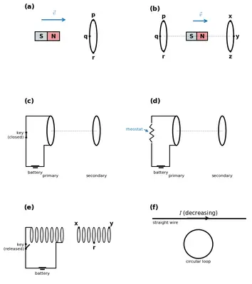
Predict the direction of induced current in the situations described by the following Figs. 6.15(a) to (f).
Fig. 6.15
Fig. 6.15

(a) A bar magnet with poles S–N is being moved towards a coil pqr (Fig. 6.15(a)). Predict the direction of the induced current.

Solution

By Lenz's law, the induced current opposes the change in flux that produces it.

In Fig. 6.15(a), the bar magnet is moving towards the coil pqr, so the magnetic flux linked with the coil is increasing. The induced current must flow so as to oppose this increase — i.e. the face of the coil towards the magnet must develop a polarity that repels the approaching magnet.

Applying this rule, the induced current in the coil flows along the path qrpq.

Answer

The induced current flows along qrpq.

(b) A bar magnet with poles S–N is being moved between two coils pqr and xyz arranged along a common axis (Fig. 6.15(b)). Predict the direction of the induced current in each coil.

Solution

The bar magnet (S–N) moves along the common axis between the two coils. As it moves, the flux through one coil increases while that through the other decreases. By Lenz's law each induced current opposes its own change of flux.

For coil pqr, the magnet is approaching, so the flux through it increases; the induced current opposes the increase and flows along prq.

For coil xyz, the magnet is receding, so the flux through it decreases; the induced current opposes the decrease and flows along yzx.

Answer

Induced current is along prq in coil pqr and along yzx in coil xyz.

(c) Two coils are placed along a common axis. A tapping key in the circuit of the first coil is just closed (Fig. 6.15(c)). Predict the direction of the induced current in the other coil.

Solution

When the tapping key of the first coil's circuit is just closed, the current in that coil grows from zero. This builds up a magnetic field, and the flux linked with the neighbouring (second) coil increases.

By Lenz's law, the induced current in the second coil opposes this increase in flux. The induced current therefore flows along yzx.

Answer

The induced current flows along yzx.

(d) Two coils are placed along a common axis. The rheostat setting in the circuit of one coil is being changed (Fig. 6.15(d)). Predict the direction of the induced current in the other coil.

Solution

Changing the rheostat setting changes the current in the first coil, and hence the flux linked with the second coil. Taking the case in which the rheostat is adjusted so that the current in the first coil decreases, the flux through the second coil decreases.

By Lenz's law, the induced current in the second coil opposes this decrease in flux, and therefore flows along zyx.

Answer

The induced current flows along zyx.

(e) Two solenoids are placed adjacent to each other with the tapping key of one just released (Fig. 6.15(e)). Predict the direction of the induced current in the loop xyr.

Solution

When the tapping key of one solenoid is just released, its circuit is broken and the current in it falls rapidly to zero. The magnetic field it produced collapses, so the flux linked with the loop xyz decreases.

By Lenz's law, the induced current in the loop opposes this decrease in flux. The induced current therefore flows along xry.

Answer

The induced current flows along xry.

(f) A current $$I$$ in a straight wire is decreasing at a steady rate. A circular loop is placed in the same plane as the wire (Fig. 6.15(f)). Predict the direction of the induced current in the loop.

Solution

The circular loop lies in the same plane as the straight current-carrying wire. The magnetic field produced by the straight wire forms concentric circles around the wire; at every point of this plane, these field lines lie in the plane of the loop itself.

Hence no magnetic field line passes through (normal to) the area of the loop — the magnetic flux linked with the loop is zero.

Even though the current $$I$$ is decreasing steadily, the flux through the loop remains zero throughout. Since there is no change of flux through the loop, no current is induced in it.

Answer

No current is induced, because the field lines lie in the plane of the loop and the flux linked with it is zero.

6.2

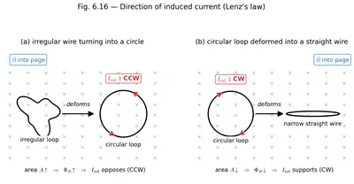
Use Lenz's law to determine the direction of induced current in the situations described by Fig. 6.16:
Fig. 6.16
Fig. 6.16

(a) A wire of irregular shape turning into a circular shape;

Solution

In Fig. 6.16(a), the magnetic field is directed into the plane of the page (shown by $$\times$$ marks). The wire of irregular shape is being turned into a circular shape.

For a given perimeter (a fixed length of wire), a circle encloses the maximum area. So as the irregular loop becomes circular, the area enclosed by it increases.

Since $$B$$ is into the page and the enclosed area increases, the magnetic flux into the page increases. By Lenz's law, the induced current must oppose this increase, i.e. it must produce a magnetic field out of the page inside the loop. This requires the induced current to flow anticlockwise, i.e. along the path adcb.

Answer

The induced current flows anticlockwise, along adcb.

(b) A circular loop being deformed into a narrow straight wire.

Solution

In Fig. 6.16(b), the magnetic field is directed out of the plane of the page (shown by dots). The circular loop is being deformed into a narrow straight wire.

For a given perimeter, a circle encloses the maximum area, while a narrow straight wire encloses almost zero area. So as the circular loop is deformed, the area enclosed by it decreases.

Since $$B$$ is out of the page and the enclosed area decreases, the magnetic flux out of the page decreases. By Lenz's law, the induced current must oppose this decrease, i.e. it must produce a magnetic field out of the page inside the loop. This requires the induced current to flow anticlockwise, i.e. along the path $$a'd'c'b'a'$$.

Answer

The induced current flows anticlockwise, along a'd'c'b'a'.

6.3 A long solenoid with $$15$$ turns per cm has a small loop of area $$2.0 \, \mathrm{cm^2}$$ placed inside the solenoid normal to its axis. If the current carried by the solenoid changes steadily from $$2.0 \, \mathrm{A}$$ to $$4.0 \, \mathrm{A}$$ in $$0.1 \, \mathrm{s}$$, what is the induced emf in the loop while the current is changing?

Solution

Given: turns per unit length $$n = 15\,\mathrm{turns/cm} = 1500\,\mathrm{turns/m}$$, area of the small loop $$A = 2.0\,\mathrm{cm^2} = 2.0\times10^{-4}\,\mathrm{m^2}$$, current changes from $$I_1 = 2.0\,\mathrm{A}$$ to $$I_2 = 4.0\,\mathrm{A}$$ in $$\Delta t = 0.1\,\mathrm{s}$$.

The magnetic field inside a long solenoid is

$$B = \mu_0 n I$$

The flux linked with the small loop (placed normal to the axis) is $$\Phi = BA = \mu_0 n I A$$. As the current changes steadily, the induced emf in the loop is

$$\varepsilon = \frac{d\Phi}{dt} = \mu_0 n A\,\frac{dI}{dt} = \mu_0 n A\,\frac{I_2 - I_1}{\Delta t}$$

The rate of change of current is

$$\frac{dI}{dt} = \frac{4.0 - 2.0}{0.1} = 20\,\mathrm{A/s}$$

Substituting all values $$(\mu_0 = 4\pi\times10^{-7}\,\mathrm{T\,m/A})$$:

$$\varepsilon = (4\pi\times10^{-7}) \times 1500 \times (2.0\times10^{-4}) \times 20$$

$$\varepsilon = (1.2566\times10^{-6}) \times 1500 \times (2.0\times10^{-4}) \times 20 \approx 7.5\times10^{-6}\,\mathrm{V}$$

The induced emf in the loop while the current is changing is about $$7.5\,\mu\mathrm{V}$$.

Answer

Induced emf $$\varepsilon \approx 7.5\times10^{-6}\,\mathrm{V}$$ (about $$7.5\,\mu\mathrm{V}$$).

6.4 A rectangular wire loop of sides $$8 \, \mathrm{cm}$$ and $$2 \, \mathrm{cm}$$ with a small cut is moving out of a region of uniform magnetic field of magnitude $$0.3 \, \mathrm{T}$$ directed normal to the loop. What is the emf developed across the cut if the velocity of the loop is $$1 \, \mathrm{cm \, s^{-1}}$$ in a direction normal to the (a) longer side, (b) shorter side of the loop? For how long does the induced voltage last in each case?

(a) longer side

Solution

Given: rectangular loop with sides $$8\,\mathrm{cm} = 0.08\,\mathrm{m}$$ (longer) and $$2\,\mathrm{cm} = 0.02\,\mathrm{m}$$ (shorter); field $$B = 0.3\,\mathrm{T}$$ normal to the loop; speed $$v = 1\,\mathrm{cm\,s^{-1}} = 0.01\,\mathrm{m\,s^{-1}}$$.

(a) Velocity normal to the longer side. When the loop moves with its velocity perpendicular to the longer side, it is the longer side $$(l = 0.08\,\mathrm{m})$$ that cuts the field lines and acts as the source of motional emf:

$$\varepsilon = B\,l\,v = 0.3 \times 0.08 \times 0.01$$

$$\varepsilon = 2.4\times10^{-4}\,\mathrm{V}$$

Duration: the emf lasts only while the loop is partly inside the field. The loop crosses the field boundary over a distance equal to its dimension along the motion, which here is the shorter side $$0.02\,\mathrm{m}$$:

$$t = \frac{\text{distance}}{v} = \frac{0.02}{0.01} = 2\,\mathrm{s}$$

So the induced emf is $$2.4\times10^{-4}\,\mathrm{V}$$ and it lasts for $$2\,\mathrm{s}$$.

Answer

Induced emf $$= 2.4\times10^{-4}\,\mathrm{V}$$, lasting for $$2\,\mathrm{s}$$.

(b) shorter side

Solution

(b) Velocity normal to the shorter side. Now the velocity is perpendicular to the shorter side, so it is the shorter side $$(l = 0.02\,\mathrm{m})$$ that cuts the field lines and acts as the source of motional emf:

$$\varepsilon = B\,l\,v = 0.3 \times 0.02 \times 0.01$$

$$\varepsilon = 6.0\times10^{-5}\,\mathrm{V}$$

Duration: the loop now crosses the field boundary over a distance equal to its longer side $$0.08\,\mathrm{m}$$:

$$t = \frac{\text{distance}}{v} = \frac{0.08}{0.01} = 8\,\mathrm{s}$$

So the induced emf is $$6.0\times10^{-5}\,\mathrm{V}$$ and it lasts for $$8\,\mathrm{s}$$.

Note: The larger emf $$(2.4\times10^{-4}\,\mathrm{V})$$ in part (a) lasts for a shorter time $$(2\,\mathrm{s})$$, while the smaller emf $$(6.0\times10^{-5}\,\mathrm{V})$$ here lasts longer $$(8\,\mathrm{s})$$.

Answer

Induced emf $$= 6.0\times10^{-5}\,\mathrm{V}$$, lasting for $$8\,\mathrm{s}$$.

6.5 A $$1.0 \, \mathrm{m}$$ long metallic rod is rotated with an angular frequency of $$400 \, \mathrm{rad \, s^{-1}}$$ about an axis normal to the rod passing through its one end. The other end of the rod is in contact with a circular metallic ring. A constant and uniform magnetic field of $$0.5 \, \mathrm{T}$$ parallel to the axis exists everywhere. Calculate the emf developed between the centre and the ring.

Solution

Given: length of rod $$L = 1.0\,\mathrm{m}$$, angular frequency $$\omega = 400\,\mathrm{rad\,s^{-1}}$$, magnetic field $$B = 0.5\,\mathrm{T}$$ parallel to the axis of rotation.

Consider a small element of length $$dr$$ of the rod at a distance $$r$$ from the fixed end. Its speed is $$v = \omega r$$, and the motional emf across it is

$$d\varepsilon = B v\, dr = B\,\omega r\, dr$$

The total emf between the centre and the rim is found by integrating from $$r = 0$$ to $$r = L$$:

$$\varepsilon = \int_0^L B\,\omega r\, dr = B\,\omega\left[\frac{r^2}{2}\right]_0^L = \frac{1}{2}B\,\omega L^2$$

Substituting the values:

$$\varepsilon = \frac{1}{2}\times 0.5 \times 400 \times (1.0)^2 = 100\,\mathrm{V}$$

The emf developed between the centre and the ring is $$100\,\mathrm{V}$$.

Answer

The emf developed is $$\varepsilon = \tfrac{1}{2}B\omega L^2 = 100\,\mathrm{V}$$.

6.6 A horizontal straight wire $$10 \, \mathrm{m}$$ long extending from east to west is falling with a speed of $$5.0 \, \mathrm{m \, s^{-1}}$$, at right angles to the horizontal component of the earth's magnetic field, $$0.30 \times 10^{-4} \, \mathrm{Wb \, m^{-2}}$$.

(a) What is the instantaneous value of the emf induced in the wire?

Solution

Given: length of wire $$l = 10\,\mathrm{m}$$, speed of fall $$v = 5.0\,\mathrm{m\,s^{-1}}$$, horizontal component of earth's field $$B = 0.30\times10^{-4}\,\mathrm{Wb\,m^{-2}}$$. The wire falls at right angles to $$B$$.

As the wire falls, it cuts the horizontal field lines, so a motional emf is induced:

$$\varepsilon = B\,l\,v$$

$$\varepsilon = (0.30\times10^{-4}) \times 10 \times 5.0$$

$$\varepsilon = 1.5\times10^{-3}\,\mathrm{V}$$

The instantaneous value of the induced emf is $$1.5\times10^{-3}\,\mathrm{V} = 1.5\,\mathrm{mV}$$.

Answer

The instantaneous induced emf is $$\varepsilon = Blv = 1.5\times10^{-3}\,\mathrm{V}$$.

(b) What is the direction of the emf?

Solution

The free charges in the wire experience the magnetic (Lorentz) force $$\mathbf{F} = q\,\mathbf{v}\times\mathbf{B}$$.

Take East as $$\hat{x}$$, North as $$\hat{y}$$ and the upward vertical as $$\hat{z}$$. The wire falls downward, so $$\mathbf{v} = -v\,\hat{z}$$. The horizontal component of the earth's field points North, so $$\mathbf{B} = B\,\hat{y}$$.

$$\mathbf{v}\times\mathbf{B} = (-v\,\hat{z})\times(B\,\hat{y}) = -vB\,(\hat{z}\times\hat{y}) = -vB\,(-\hat{x}) = vB\,\hat{x}$$

So the force on a positive charge is directed along $$+\hat{x}$$, i.e. towards the East. The induced emf therefore acts from the West end to the East end of the wire.

Answer

The emf is directed from the West end to the East end of the wire.

(c) Which end of the wire is at the higher electrical potential?

Solution

From part (b), the magnetic force pushes positive charges towards the East end of the wire. Positive charge therefore accumulates at the East end, leaving the West end negative.

Hence the East end of the wire is at the higher electrical potential.

Answer

The East end of the wire is at the higher potential.

6.7 Current in a circuit falls from $$5.0 \, \mathrm{A}$$ to $$0.0 \, \mathrm{A}$$ in $$0.1 \, \mathrm{s}$$. If an average emf of $$200 \, \mathrm{V}$$ induced, give an estimate of the self-inductance of the circuit.

Solution

Given: current falls from $$I_1 = 5.0\,\mathrm{A}$$ to $$I_2 = 0.0\,\mathrm{A}$$ in $$\Delta t = 0.1\,\mathrm{s}$$; average induced emf $$\varepsilon = 200\,\mathrm{V}$$.

The self-induced (back) emf in a circuit of self-inductance $$L$$ has magnitude

$$\varepsilon = L\left|\frac{dI}{dt}\right| = L\,\frac{|I_2 - I_1|}{\Delta t}$$

Solving for $$L$$:

$$L = \frac{\varepsilon\,\Delta t}{|I_2 - I_1|} = \frac{200 \times 0.1}{|0 - 5.0|}$$

$$L = \frac{20}{5.0} = 4\,\mathrm{H}$$

The estimated self-inductance of the circuit is $$4\,\mathrm{H}$$ (henry).

Answer

The self-inductance is $$L = 4\,\mathrm{H}$$.

6.8 A pair of adjacent coils has a mutual inductance of $$1.5 \, \mathrm{H}$$. If the current in one coil changes from $$0$$ to $$20 \, \mathrm{A}$$ in $$0.5 \, \mathrm{s}$$, what is the change of flux linkage with the other coil?

Solution

Given: mutual inductance $$M = 1.5\,\mathrm{H}$$; current in one coil changes from $$I_1 = 0$$ to $$I_2 = 20\,\mathrm{A}$$ in $$\Delta t = 0.5\,\mathrm{s}$$.

The flux linkage with the second coil due to the current in the first is $$N\Phi = M I$$. Hence the change in flux linkage with the other coil is

$$\Delta(N\Phi) = M\,\Delta I = M\,(I_2 - I_1)$$

$$\Delta(N\Phi) = 1.5 \times (20 - 0)$$

$$\Delta(N\Phi) = 30\,\mathrm{Wb}$$

The change of flux linkage with the other coil is $$30\,\mathrm{Wb}$$ (weber). The time interval $$0.5\,\mathrm{s}$$ is not needed for the change in flux linkage itself; it would be required only to find the average induced emf, $$\varepsilon = \Delta(N\Phi)/\Delta t = 60\,\mathrm{V}$$.

Answer

The change of flux linkage is $$\Delta(N\Phi) = M\,\Delta I = 30\,\mathrm{Wb}$$.
NCERT Solutions for Class 12
Maths
NCERT Solutions for Class 12 Maths
Chapter-wise step-by-step
solutions with explanations
explore solutions Maths bg
Physics
NCERT Solutions for Class 12 Physics
Chapter-wise step-by-step
solutions with explanations
explore solutions Physics bg
Chemistry
NCERT Solutions for Class 12 Chemistry
Chapter-wise step-by-step
solutions with explanations
explore solutions Chemistry bg

Frequently Asked Questions

50,000+ JEE Students Trusted Our Score Calculator

Predict your JEE Main percentile, rank & performance in seconds