Join WhatsApp Icon JEE WhatsApp Group
NCERT Solutions for Class 12 Physics

Chapter 3: Current Electricity

Download Solutions PDF
Daily JEE Updates, Tips & Important Alerts
Join 30,000+ students and stay updated with JEE notifications and preparation insights.
Join Now!
Free PDF
Complete NCERT Solution PDF for Chapter 3: Current Electricity

NCERT Solutions For Class 12 Physics Chapter 3 Current Electricity helps students understand the movement of electric charges and the principles governing electrical circuits. The page provides detailed NCERT Solutions that explain concepts such as electric current, resistance, Ohm’s law, Kirchhoff’s laws, resistivity, and electrical energy. NCERT Solutions For Class 12 Physics simplify circuit-related concepts through solved examples and systematic explanations. The chapter develops essential skills required for solving numerical problems related to electrical circuits. These solutions help students understand the practical applications of electricity and improve their problem-solving approach. Students can use the chapter PDF for revision, practice, and examination preparation. The structured content makes current electricity concepts easier to learn and apply.

Download Solutions PDF

Examples

Example 3.1

(a) Estimate the average drift speed of conduction electrons in a copper wire of cross-sectional area $$1.0 \times 10^{-7} \, \mathrm{m^2}$$ carrying a current of $$1.5 \, \mathrm{A}$$. Assume that each copper atom contributes roughly one conduction electron. The density of copper is $$9.0 \times 10^{3} \, \mathrm{kg/m^3}$$, and its atomic mass is $$63.5 \, \mathrm{u}$$.

(b) Compare the drift speed obtained above with, (i) thermal speeds of copper atoms at ordinary temperatures, (ii) speed of propagation of electric field along the conductor which causes the drift motion.

Solution

(a) Drift speed.

The current is related to the drift speed by $$I = n e A v_d$$, where $$n$$ is the number density of conduction electrons, $$e$$ the electronic charge, $$A$$ the cross-sectional area and $$v_d$$ the drift speed. Hence $$v_d = \dfrac{I}{n e A}$$.

Step 1 — find the electron number density $$n$$. The number of copper atoms per unit volume is $$\dfrac{\rho_m N_A}{M}$$, and since each atom contributes one conduction electron, $$n$$ equals this quantity. With density $$\rho_m = 9.0 \times 10^{3} \, \mathrm{kg/m^3}$$, Avogadro number $$N_A = 6.0 \times 10^{23} \, \mathrm{mol^{-1}}$$ and atomic mass $$M = 63.5 \, \mathrm{u} = 63.5 \times 10^{-3} \, \mathrm{kg/mol}$$:

$$n = \dfrac{(9.0 \times 10^{3})(6.0 \times 10^{23})}{63.5 \times 10^{-3}} \approx 8.5 \times 10^{28} \, \mathrm{m^{-3}}$$

Step 2 — find $$v_d$$. Substituting $$I = 1.5 \, \mathrm{A}$$, $$e = 1.6 \times 10^{-19} \, \mathrm{C}$$ and $$A = 1.0 \times 10^{-7} \, \mathrm{m^2}$$:

$$v_d = \dfrac{1.5}{(8.5 \times 10^{28})(1.6 \times 10^{-19})(1.0 \times 10^{-7})} = \dfrac{1.5}{1.36 \times 10^{3}}$$

$$v_d \approx 1.1 \times 10^{-3} \, \mathrm{m\,s^{-1}} = 1.1 \, \mathrm{mm\,s^{-1}}$$

(b) Comparisons.

(i) With the thermal speed of the atoms. At an ordinary temperature ($$T \approx 300 \, \mathrm{K}$$) the random thermal speed of a copper atom is of the order $$v_{th} \sim \sqrt{\dfrac{3 k_B T}{M_{atom}}} \sim 10^{2} \, \mathrm{m\,s^{-1}}$$. The drift speed is therefore smaller than the thermal speed by a factor of about $$10^{-5}$$.

(ii) With the speed of propagation of the field. When the circuit is closed the electric field is set up throughout the conductor with a speed close to that of light, $$\sim 3 \times 10^{8} \, \mathrm{m\,s^{-1}}$$. The drift speed is smaller than this by a factor of about $$10^{-11}$$.

Answer

$$v_d \approx 1.1 \times 10^{-3} \, \mathrm{m\,s^{-1}}$$ (about $$1.1 \, \mathrm{mm\,s^{-1}}$$). It is smaller than the thermal speed of the atoms by a factor $$\sim 10^{-5}$$ and smaller than the speed of propagation of the field by a factor $$\sim 10^{-11}$$.

Example 3.2

(a) In Example 3.1, the electron drift speed is estimated to be only a few $$\mathrm{mm \, s^{-1}}$$ for currents in the range of a few amperes? How then is current established almost the instant a circuit is closed?

Solution

The current is not established by an electron physically travelling from one end of the wire to the other. When the circuit is closed, an electric field is set up inside the conductor, and this field propagates along the conductor with a speed close to the speed of light ($$\sim 3 \times 10^{8} \, \mathrm{m\,s^{-1}}$$).

Within an extremely short time the field reaches every part of the circuit, so the electrons everywhere in the conductor begin to drift almost simultaneously. Since it is the field — not the individual electrons — that carries the "signal", the current is established practically the instant the circuit is closed, even though each electron itself drifts only a few $$\mathrm{mm\,s^{-1}}$$.

Answer

Closing the circuit sets up an electric field along the whole conductor almost at the speed of light; electrons everywhere begin to drift at nearly the same instant, so the current appears immediately even though the drift speed itself is tiny.

(b) The electron drift arises due to the force experienced by electrons in the electric field inside the conductor. But force should cause acceleration. Why then do the electrons acquire a steady average drift speed?

Solution

The electric field does exert a force $$eE$$ on each electron, and between collisions the electron is indeed accelerated. However, an electron does not move freely for long — it repeatedly collides with the positive ions of the metal lattice.

At each collision the electron's velocity is randomised, so the extra velocity gained from the field is lost. The field then accelerates the electron afresh, but only for the short average time $$\tau$$ (the relaxation time) between two collisions. The velocity gained before the next collision is thus only $$\dfrac{eE}{m}\tau$$.

Averaged over a very large number of collisions, this produces a small but steady average velocity — the drift velocity $$v_d = \dfrac{eE\tau}{m}$$ — rather than an ever-increasing speed. The accelerating effect of the field is continually balanced by the randomising effect of the collisions.

Answer

Electrons accelerate only during the short relaxation time $$\tau$$ between collisions, and each collision randomises their velocity. The result is a constant average (drift) velocity $$v_d = eE\tau/m$$, not unlimited acceleration.

(c) If the electron drift speed is so small, and the electron's charge is small, how can we still obtain large amounts of current in a conductor?

Solution

The magnitude of the current is given by $$I = n e A v_d$$.

Although the electron charge $$e$$ and the drift speed $$v_d$$ are both very small, the number density $$n$$ of free electrons in a metal is extremely large — of the order of $$10^{29} \, \mathrm{m^{-3}}$$. Even a short length of an ordinary conductor therefore contains an enormous number of charge carriers.

The product $$n e A v_d$$ can thus be of the order of an ampere or more. It is the huge number of free electrons that compensates for the smallness of $$e$$ and $$v_d$$ and makes large currents possible.

Answer

Because the number density of free electrons $$n \sim 10^{29} \, \mathrm{m^{-3}}$$ is enormous, the product $$I = n e A v_d$$ is large even though $$e$$ and $$v_d$$ are individually tiny.

(d) When electrons drift in a metal from lower to higher potential, does it mean that all the 'free' electrons of the metal are moving in the same direction?

Solution

No. Even with no field applied, the free electrons of a metal are in rapid random thermal motion, moving in all possible directions with speeds of the order of $$10^{5} \, \mathrm{m\,s^{-1}}$$. Averaged over all the electrons, this random velocity is zero.

When a field is applied, a very small drift velocity ($$\sim \mathrm{mm\,s^{-1}}$$) is merely superimposed on this large random motion. Only the average (net) velocity of the electrons is directed (opposite to the field $$\vec E$$); the individual electrons still move in all directions. So it is not true that all the free electrons move in the same direction.

Answer

No. The free electrons keep their large random thermal motion in all directions; only their small average (drift) velocity is along one direction.

(e) Are the paths of electrons straight lines between successive collisions (with the positive ions of the metal) in the (i) absence of electric field, (ii) presence of electric field?

Solution

(i) In the absence of an electric field: Yes. Between two successive collisions no force acts on the electron, so it moves with constant velocity. Its path between collisions is therefore a straight line.

(ii) In the presence of an electric field: No. The field exerts a constant force $$eE$$ on the electron, giving it a constant acceleration between collisions. Under a constant force the path is curved (a parabolic arc), just like the path of a projectile, rather than a straight line.

Answer

(i) Yes — with no force acting, the electron travels in a straight line between collisions. (ii) No — the field gives a constant acceleration, so the path between collisions is a curved (parabolic) arc.

Example 3.3 An electric toaster uses nichrome for its heating element. When a negligibly small current passes through it, its resistance at room temperature ($$27.0 \, °\mathrm{C}$$) is found to be $$75.3 \, \Omega$$. When the toaster is connected to a $$230 \, \mathrm{V}$$ supply, the current settles, after a few seconds, to a steady value of $$2.68 \, \mathrm{A}$$. What is the steady temperature of the nichrome element? The temperature coefficient of resistance of nichrome averaged over the temperature range involved, is $$1.70 \times 10^{-4} \, °\mathrm{C}^{-1}$$.

Solution

When a negligibly small current flows, the element is at room temperature $$T_1 = 27.0 \, °\mathrm{C}$$ and its resistance is $$R_1 = 75.3 \, \Omega$$.

When the toaster is connected to the supply, at the steady temperature $$T_2$$ the resistance is obtained from Ohm's law:

$$R_2 = \dfrac{V}{I} = \dfrac{230 \, \mathrm{V}}{2.68 \, \mathrm{A}} \approx 85.8 \, \Omega$$

The resistance varies with temperature as $$R_2 = R_1\left[1 + \alpha (T_2 - T_1)\right]$$, so

$$T_2 - T_1 = \dfrac{R_2 - R_1}{R_1 \, \alpha}$$

$$T_2 - T_1 = \dfrac{85.8 - 75.3}{75.3 \times 1.70 \times 10^{-4}} = \dfrac{10.5}{1.28 \times 10^{-2}} \approx 820 \, °\mathrm{C}$$

$$T_2 = 27 + 820 = 847 \, °\mathrm{C}$$

Answer

The steady temperature of the nichrome element is about $$847 \, °\mathrm{C}$$.

Example 3.4 The resistance of the platinum wire of a platinum resistance thermometer at the ice point is $$5 \, \Omega$$ and at steam point is $$5.23 \, \Omega$$. When the thermometer is inserted in a hot bath, the resistance of the platinum wire is $$5.795 \, \Omega$$. Calculate the temperature of the bath.

Solution

For a platinum resistance thermometer the resistance is taken to vary linearly with temperature. The temperature $$t$$ corresponding to a resistance $$R_t$$ is found by linear interpolation between the ice point ($$0 \, °\mathrm{C}$$) and the steam point ($$100 \, °\mathrm{C}$$):

$$t = \dfrac{R_t - R_0}{R_{100} - R_0} \times 100 \, °\mathrm{C}$$

Here $$R_0 = 5 \, \Omega$$ (ice point), $$R_{100} = 5.23 \, \Omega$$ (steam point) and $$R_t = 5.795 \, \Omega$$ (hot bath). Substituting:

$$t = \dfrac{5.795 - 5}{5.23 - 5} \times 100 = \dfrac{0.795}{0.23} \times 100$$

$$t = 3.4565 \times 100 \approx 345.65 \, °\mathrm{C}$$

Answer

The temperature of the bath is about $$345.65 \, °\mathrm{C}$$.

Example 3.5

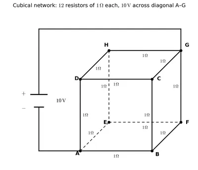
A battery of $$10 \, \mathrm{V}$$ and negligible internal resistance is connected across the diagonally opposite corners of a cubical network consisting of 12 resistors each of resistance $$1 \, \Omega$$ (Fig. 3.16). Determine the equivalent resistance of the network and the current along each edge of the cube.
Fig. 3.16
Fig. 3.16

Solution

The network of 12 equal resistors cannot be reduced by simple series–parallel rules, but the symmetry of the cube about the diagonal can be exploited.

Using symmetry and the junction rule. Let a total current $$3I$$ enter at corner A and leave at the diagonally opposite corner C'. The three edges meeting at A (namely AA', AD and AB) are symmetrically placed, so each must carry the same current $$I$$.

At the next corners (A', D and B) each incoming current $$I$$ splits equally into the two outgoing edges, so those edges each carry $$I/2$$. By the same symmetry, at the three corners adjacent to C' (D', B' and C) two currents of $$I/2$$ recombine, so each of the three edges leading into C' again carries $$I$$. This fixes the current in every one of the 12 edges.

Applying the loop rule. Take the closed loop A → B → C → C' (each edge has resistance $$R$$) together with the battery of emf $$\varepsilon$$. Going around:

$$\varepsilon = I R + \dfrac{I}{2} R + I R = \dfrac{5}{2} I R$$

The equivalent resistance is the emf divided by the total current $$3I$$ drawn from the battery:

$$R_{eq} = \dfrac{\varepsilon}{3I} = \dfrac{(5/2) I R}{3 I} = \dfrac{5}{6} R$$

With $$R = 1 \, \Omega$$:

$$R_{eq} = \dfrac{5}{6} \, \Omega \approx 0.83 \, \Omega$$

Currents along the edges. The total current drawn from the $$10 \, \mathrm{V}$$ battery is

$$3I = \dfrac{\varepsilon}{R_{eq}} = \dfrac{10}{5/6} = 12 \, \mathrm{A} \quad\Rightarrow\quad I = 4 \, \mathrm{A}$$

Hence the three edges meeting at A and the three edges meeting at C' each carry $$I = 4 \, \mathrm{A}$$, while each of the remaining six (middle) edges carries $$I/2 = 2 \, \mathrm{A}$$.

Answer

Equivalent resistance $$R_{eq} = \dfrac{5}{6} \, \Omega \approx 0.83 \, \Omega$$. The six edges touching the input corner A and output corner C' carry $$4 \, \mathrm{A}$$ each; the other six edges carry $$2 \, \mathrm{A}$$ each (total current $$12 \, \mathrm{A}$$).

Example 3.6

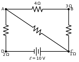
Determine the current in each branch of the network shown in Fig. 3.17.
Fig. 3.17
Fig. 3.17

Solution

Assign a current to each branch and reduce the number of unknowns by applying the junction rule at every junction as the currents are labelled. As in Fig. 3.17, take $$I_1$$, $$I_2$$ and $$I_3$$ as the three independent currents; the current in every branch is then written in terms of them.

Loop ADCA. Applying Kirchhoff's loop rule:

$$10 - 4(I_1 - I_2) + 2(I_2 + I_3 - I_1) - I_1 = 0$$

$$\Rightarrow \; 7 I_1 - 6 I_2 - 2 I_3 = 10 \quad\text{...(1)}$$

Loop ABCA.

$$10 - 4 I_2 - 2(I_2 + I_3) - I_1 = 0$$

$$\Rightarrow \; I_1 + 6 I_2 + 2 I_3 = 10 \quad\text{...(2)}$$

Loop BCDEB.

$$5 - 2(I_2 + I_3) - 2(I_2 + I_3 - I_1) = 0$$

$$\Rightarrow \; 2 I_1 - 4 I_2 - 4 I_3 = -5 \quad\text{...(3)}$$

Solving the three equations. Adding (1) and (2):

$$8 I_1 = 20 \quad\Rightarrow\quad I_1 = 2.5 \, \mathrm{A}$$

Put $$I_1 = 2.5$$ in (2): $$2.5 + 6 I_2 + 2 I_3 = 10$$, i.e. $$3 I_2 + I_3 = 3.75$$.
Put $$I_1 = 2.5$$ in (3): $$5 - 4 I_2 - 4 I_3 = -5$$, i.e. $$I_2 + I_3 = 2.5$$.

Subtracting the second from the first: $$2 I_2 = 1.25$$, so

$$I_2 = \dfrac{5}{8} \, \mathrm{A} = 0.625 \, \mathrm{A}, \qquad I_3 = 2.5 - 0.625 = \dfrac{15}{8} \, \mathrm{A} = 1.875 \, \mathrm{A}$$

Current in each branch.

BranchCurrent
AB$$I_2 = \dfrac{5}{8} \, \mathrm{A}$$
CA$$I_1 = 2\dfrac{1}{2} \, \mathrm{A}$$
BC$$I_2 + I_3 = 2\dfrac{1}{2} \, \mathrm{A}$$
AD$$I_1 - I_2 = 1\dfrac{7}{8} \, \mathrm{A}$$
DEB$$I_3 = 1\dfrac{7}{8} \, \mathrm{A}$$
CD$$I_2 + I_3 - I_1 = 0 \, \mathrm{A}$$

It may be verified that these values satisfy Kirchhoff's loop rule for every other closed loop of the network as well.

Answer

$$I_1 = 2.5 \, \mathrm{A}$$, $$I_2 = \dfrac{5}{8} \, \mathrm{A}$$, $$I_3 = \dfrac{15}{8} \, \mathrm{A}$$. Branch currents: AB $$= \dfrac{5}{8} \, \mathrm{A}$$, CA $$= \dfrac{5}{2} \, \mathrm{A}$$, BC $$= \dfrac{5}{2} \, \mathrm{A}$$, AD $$= \dfrac{15}{8} \, \mathrm{A}$$, DEB $$= \dfrac{15}{8} \, \mathrm{A}$$, CD $$= 0$$.

Example 3.7

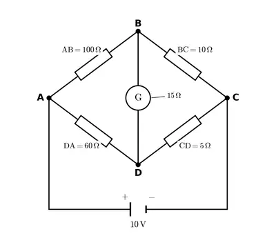
The four arms of a Wheatstone bridge (Fig. 3.19) have the following resistances: $$\mathrm{AB} = 100 \, \Omega$$, $$\mathrm{BC} = 10 \, \Omega$$, $$\mathrm{CD} = 5 \, \Omega$$, and $$\mathrm{DA} = 60 \, \Omega$$. A galvanometer of $$15 \, \Omega$$ resistance is connected across BD. Calculate the current through the galvanometer when a potential difference of $$10 \, \mathrm{V}$$ is maintained across AC.
Fig. 3.19
Fig. 3.19

Solution

Let $$I_1$$ be the current entering at A through arm AB and $$I_2$$ the current entering at A through arm AD. Let $$I_g$$ be the current through the galvanometer, taken from B to D. By the junction rule the current in BC is $$I_1 - I_g$$ and the current in DC is $$I_2 + I_g$$.

Mesh BADB. Applying the loop rule around B → A → D → B:

$$100 I_1 + 15 I_g - 60 I_2 = 0$$

Dividing by 5: $$\;\; 20 I_1 + 3 I_g - 12 I_2 = 0 \quad\text{...(a)}$$

Mesh BCDB. Around B → C → D → B:

$$10(I_1 - I_g) - 5(I_2 + I_g) - 15 I_g = 0$$

$$10 I_1 - 30 I_g - 5 I_2 = 0 \;\Rightarrow\; 2 I_1 - 6 I_g - I_2 = 0 \quad\text{...(b)}$$

Mesh ADCEA. This loop contains the $$10 \, \mathrm{V}$$ source:

$$60 I_2 + 5(I_2 + I_g) = 10$$

$$65 I_2 + 5 I_g = 10 \;\Rightarrow\; 13 I_2 + I_g = 2 \quad\text{...(c)}$$

Solving. Multiply (b) by 10: $$\;20 I_1 - 60 I_g - 10 I_2 = 0$$ ...(d).
Subtract (a) from (d):

$$(20 I_1 - 60 I_g - 10 I_2) - (20 I_1 + 3 I_g - 12 I_2) = 0$$

$$-63 I_g + 2 I_2 = 0 \quad\Rightarrow\quad I_2 = 31.5 \, I_g$$

Substitute $$I_2 = 31.5 \, I_g$$ into (c):

$$13 (31.5 \, I_g) + I_g = 2$$

$$409.5 \, I_g + I_g = 2 \quad\Rightarrow\quad 410.5 \, I_g = 2$$

$$I_g = \dfrac{2}{410.5} \approx 4.87 \times 10^{-3} \, \mathrm{A}$$

Answer

The current through the galvanometer is $$I_g \approx 4.87 \, \mathrm{mA}$$.

Exercises

3.1 The storage battery of a car has an emf of $$12 \, \mathrm{V}$$. If the internal resistance of the battery is $$0.4 \, \Omega$$, what is the maximum current that can be drawn from the battery?

Solution

The maximum current is drawn when the external resistance is zero (the terminals short-circuited), so the only resistance limiting the current is the internal resistance $$r$$ of the battery.

From $$\varepsilon = I(R + r)$$ with $$R = 0$$:

$$I_{max} = \dfrac{\varepsilon}{r} = \dfrac{12 \, \mathrm{V}}{0.4 \, \Omega} = 30 \, \mathrm{A}$$

(In practice such a large current would damage the battery; it cannot be drawn safely for long.)

Answer

The maximum current that can be drawn is $$I_{max} = 30 \, \mathrm{A}$$.

3.2 A battery of emf $$10 \, \mathrm{V}$$ and internal resistance $$3 \, \Omega$$ is connected to a resistor. If the current in the circuit is $$0.5 \, \mathrm{A}$$, what is the resistance of the resistor? What is the terminal voltage of the battery when the circuit is closed?

Solution

For a cell of emf $$\varepsilon$$ and internal resistance $$r$$ connected to an external resistance $$R$$, the current is

$$I = \dfrac{\varepsilon}{R + r}$$

Rearranging to find $$R$$:

$$R + r = \dfrac{\varepsilon}{I} = \dfrac{10}{0.5} = 20 \, \Omega$$

$$R = 20 - r = 20 - 3 = 17 \, \Omega$$

The terminal voltage of the battery is the potential difference across the external resistor:

$$V = I R = 0.5 \times 17 = 8.5 \, \mathrm{V}$$

Equivalently, $$V = \varepsilon - I r = 10 - 0.5 \times 3 = 8.5 \, \mathrm{V}$$ — the terminal voltage is less than the emf because of the drop $$Ir$$ across the internal resistance.

Answer

Resistance of the resistor $$R = 17 \, \Omega$$; terminal voltage of the battery $$V = 8.5 \, \mathrm{V}$$.

3.3 At room temperature ($$27.0 \, °\mathrm{C}$$) the resistance of a heating element is $$100 \, \Omega$$. What is the temperature of the element if the resistance is found to be $$117 \, \Omega$$, given that the temperature coefficient of the material of the resistor is $$1.70 \times 10^{-4} \, °\mathrm{C}^{-1}$$.

Solution

The resistance varies with temperature as

$$R = R_0\left[1 + \alpha (T - T_0)\right]$$

where $$R_0 = 100 \, \Omega$$ at $$T_0 = 27.0 \, °\mathrm{C}$$, $$R = 117 \, \Omega$$ and $$\alpha = 1.70 \times 10^{-4} \, °\mathrm{C}^{-1}$$. Solving for the temperature $$T$$:

$$T - T_0 = \dfrac{R - R_0}{R_0 \, \alpha} = \dfrac{117 - 100}{100 \times 1.70 \times 10^{-4}}$$

$$T - T_0 = \dfrac{17}{1.70 \times 10^{-2}} = 1000 \, °\mathrm{C}$$

$$T = 27 + 1000 = 1027 \, °\mathrm{C}$$

Answer

The temperature of the element is $$T = 1027 \, °\mathrm{C}$$.

3.4 A negligibly small current is passed through a wire of length $$15 \, \mathrm{m}$$ and uniform cross-section $$6.0 \times 10^{-7} \, \mathrm{m^2}$$, and its resistance is measured to be $$5.0 \, \Omega$$. What is the resistivity of the material at the temperature of the experiment?

Solution

The resistance of a uniform wire is related to its resistivity by

$$R = \dfrac{\rho \, l}{A} \quad\Rightarrow\quad \rho = \dfrac{R \, A}{l}$$

Substituting $$R = 5.0 \, \Omega$$, $$A = 6.0 \times 10^{-7} \, \mathrm{m^2}$$ and $$l = 15 \, \mathrm{m}$$:

$$\rho = \dfrac{5.0 \times (6.0 \times 10^{-7})}{15} = \dfrac{30 \times 10^{-7}}{15}$$

$$\rho = 2.0 \times 10^{-7} \, \Omega\,\mathrm{m}$$

Answer

The resistivity of the material is $$\rho = 2.0 \times 10^{-7} \, \Omega\,\mathrm{m}$$.

3.5 A silver wire has a resistance of $$2.1 \, \Omega$$ at $$27.5 \, °\mathrm{C}$$, and a resistance of $$2.7 \, \Omega$$ at $$100 \, °\mathrm{C}$$. Determine the temperature coefficient of resistivity of silver.

Solution

The resistance at temperature $$T_2$$ is related to that at $$T_1$$ through the temperature coefficient $$\alpha$$:

$$R_2 = R_1\left[1 + \alpha (T_2 - T_1)\right]$$

so that

$$\alpha = \dfrac{R_2 - R_1}{R_1 (T_2 - T_1)}$$

Here $$R_1 = 2.1 \, \Omega$$ at $$T_1 = 27.5 \, °\mathrm{C}$$ and $$R_2 = 2.7 \, \Omega$$ at $$T_2 = 100 \, °\mathrm{C}$$. Substituting:

$$\alpha = \dfrac{2.7 - 2.1}{2.1 \times (100 - 27.5)} = \dfrac{0.6}{2.1 \times 72.5}$$

$$\alpha = \dfrac{0.6}{152.25} \approx 3.9 \times 10^{-3} \, °\mathrm{C}^{-1}$$

Answer

The temperature coefficient of resistivity of silver is $$\alpha \approx 3.9 \times 10^{-3} \, °\mathrm{C}^{-1}$$ (about $$0.0039 \, °\mathrm{C}^{-1}$$).

3.6 A heating element using nichrome connected to a $$230 \, \mathrm{V}$$ supply draws an initial current of $$3.2 \, \mathrm{A}$$ which settles after a few seconds to a steady value of $$2.8 \, \mathrm{A}$$. What is the steady temperature of the heating element if the room temperature is $$27.0 \, °\mathrm{C}$$? Temperature coefficient of resistance of nichrome averaged over the temperature range involved is $$1.70 \times 10^{-4} \, °\mathrm{C}^{-1}$$.

Solution

The resistance of the element is found from Ohm's law at the two stages.

Cold stage (room temperature $$T_1 = 27.0 \, °\mathrm{C}$$): the initial current is $$3.2 \, \mathrm{A}$$, so

$$R_1 = \dfrac{V}{I_1} = \dfrac{230}{3.2} = 71.87 \, \Omega$$

Hot stage (steady temperature $$T_2$$): the current settles to $$2.8 \, \mathrm{A}$$, so

$$R_2 = \dfrac{V}{I_2} = \dfrac{230}{2.8} = 82.14 \, \Omega$$

Using $$R_2 = R_1\left[1 + \alpha (T_2 - T_1)\right]$$:

$$T_2 - T_1 = \dfrac{R_2 - R_1}{R_1 \, \alpha} = \dfrac{82.14 - 71.87}{71.87 \times 1.70 \times 10^{-4}}$$

$$T_2 - T_1 = \dfrac{10.27}{1.22 \times 10^{-2}} \approx 840 \, °\mathrm{C}$$

$$T_2 = 27 + 840 = 867 \, °\mathrm{C}$$

Answer

The steady temperature of the heating element is about $$867 \, °\mathrm{C}$$.

3.7

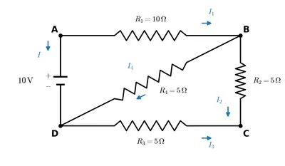
Determine the current in each branch of the network shown in Fig. 3.20.
Fig. 3.20
Fig. 3.20

Solution

The network of Fig. 3.20 is a Wheatstone-bridge type arrangement. Label the corners A (left), B (top), C (right) and D (bottom). The arms are $$AB = 10 \, \Omega$$, $$BC = 5 \, \Omega$$, $$AD = 5 \, \Omega$$, $$DC = 10 \, \Omega$$, and the bridge arm $$BD = 5 \, \Omega$$. A $$10 \, \mathrm{V}$$ battery is connected across A and C through a series resistor of $$10 \, \Omega$$.

Check for balance. A balanced bridge would require $$\dfrac{AB}{BC} = \dfrac{AD}{DC}$$. Here $$\dfrac{10}{5} = 2$$ but $$\dfrac{5}{10} = 0.5$$, so the bridge is unbalanced — a current flows through BD, and Kirchhoff's rules must be used.

Labelling the currents. Let the total current $$I$$ enter at A and split into $$x$$ through AB and $$(I - x)$$ through AD. Let $$g$$ be the current in the bridge arm BD (taken from B to D). By the junction rule the current in BC is $$x - g$$ and in DC is $$I - x + g$$.

Loop ABDA. Applying the loop rule:

$$10x + 5g - 5(I - x) = 0 \;\Rightarrow\; 15x + 5g - 5I = 0 \;\Rightarrow\; 3x + g = I \quad\text{...(1)}$$

Loop BCDB.

$$5(x - g) - 10(I - x + g) - 5g = 0$$

$$15x - 20g - 10I = 0 \;\Rightarrow\; 3x - 4g - 2I = 0 \quad\text{...(2)}$$

Substituting $$I = 3x + g$$ from (1) into (2):

$$3x - 4g - 2(3x + g) = 0 \;\Rightarrow\; -3x - 6g = 0 \;\Rightarrow\; x = -2g$$

So $$g = -\dfrac{x}{2}$$, and therefore $$I = 3x + g = 3x - \dfrac{x}{2} = \dfrac{5x}{2}$$.

Outer loop (battery → 10 Ω → A → B → C). Applying the loop rule to the $$10 \, \mathrm{V}$$ source:

$$10 = 10 I + 10x + 5(x - g)$$

$$10 = 10\left(\dfrac{5x}{2}\right) + 10x + 5\left(x + \dfrac{x}{2}\right) = 25x + 10x + 7.5x = 42.5\,x$$

$$x = \dfrac{10}{42.5} = \dfrac{4}{17} \, \mathrm{A} \approx 0.235 \, \mathrm{A}$$

Hence the total current is

$$I = \dfrac{5x}{2} = \dfrac{5}{2}\times\dfrac{4}{17} = \dfrac{10}{17} \, \mathrm{A} \approx 0.588 \, \mathrm{A}$$

and the bridge current is $$g = -\dfrac{x}{2} = -\dfrac{2}{17} \, \mathrm{A}$$; the minus sign shows it actually flows from D to B.

Current in each branch.

BranchCurrent
AB ($$10 \, \Omega$$)$$x = \dfrac{4}{17} \approx 0.235 \, \mathrm{A}$$
AD ($$5 \, \Omega$$)$$I - x = \dfrac{6}{17} \approx 0.353 \, \mathrm{A}$$
BC ($$5 \, \Omega$$)$$x - g = \dfrac{6}{17} \approx 0.353 \, \mathrm{A}$$
DC ($$10 \, \Omega$$)$$I - x + g = \dfrac{4}{17} \approx 0.235 \, \mathrm{A}$$
BD ($$5 \, \Omega$$)$$\dfrac{2}{17} \approx 0.118 \, \mathrm{A}$$ (from D to B)
Battery and $$10 \, \Omega$$$$I = \dfrac{10}{17} \approx 0.588 \, \mathrm{A}$$

As a check, the voltage across the bridge network (A to C) is $$V_{AC} = 10 - 10 I = 10 - \dfrac{100}{17} = \dfrac{70}{17} \, \mathrm{V}$$, giving an equivalent resistance $$\dfrac{V_{AC}}{I} = 7 \, \Omega$$; with the series $$10 \, \Omega$$ the total is $$17 \, \Omega$$, consistent with $$I = \dfrac{10}{17} \, \mathrm{A}$$.

Answer

Total current drawn from the battery $$= \dfrac{10}{17} \approx 0.588 \, \mathrm{A}$$. Branch currents: AB and DC carry $$\dfrac{4}{17} \approx 0.235 \, \mathrm{A}$$ each; AD and BC carry $$\dfrac{6}{17} \approx 0.353 \, \mathrm{A}$$ each; the bridge arm BD carries $$\dfrac{2}{17} \approx 0.118 \, \mathrm{A}$$ (from D to B).

3.8 A storage battery of emf $$8.0 \, \mathrm{V}$$ and internal resistance $$0.5 \, \Omega$$ is being charged by a $$120 \, \mathrm{V}$$ dc supply using a series resistor of $$15.5 \, \Omega$$. What is the terminal voltage of the battery during charging? What is the purpose of having a series resistor in the charging circuit?

Solution

During charging, the $$120 \, \mathrm{V}$$ dc supply drives current into the battery, i.e. against the battery's own emf. The two emf's therefore oppose each other, so the effective emf driving the current is

$$\varepsilon_{net} = 120 - 8.0 = 112 \, \mathrm{V}$$

The total resistance in the circuit is the series resistor plus the battery's internal resistance:

$$R_{total} = 15.5 + 0.5 = 16 \, \Omega$$

So the charging current is

$$I = \dfrac{\varepsilon_{net}}{R_{total}} = \dfrac{112}{16} = 7.0 \, \mathrm{A}$$

Terminal voltage during charging. While the battery is being charged the current flows into its positive terminal, so the terminal voltage exceeds the emf by the drop $$Ir$$ across the internal resistance:

$$V = \varepsilon + I r = 8.0 + 7.0 \times 0.5 = 11.5 \, \mathrm{V}$$

(Check: the terminal voltage also equals the supply voltage minus the drop across the series resistor, $$V = 120 - I \times 15.5 = 120 - 108.5 = 11.5 \, \mathrm{V}$$.)

Purpose of the series resistor. It limits the charging current to a safe value. Without it the current would be $$\dfrac{112}{0.5} = 224 \, \mathrm{A}$$, which would severely overheat and damage the battery. The series resistor keeps the charging current small and protects the battery.

Answer

Terminal voltage of the battery during charging is $$V = 11.5 \, \mathrm{V}$$. The series resistor limits the charging current (here to $$7.0 \, \mathrm{A}$$) to a safe value and so protects the battery from damage.

3.9 The number density of free electrons in a copper conductor estimated in Example 3.1 is $$8.5 \times 10^{28} \, \mathrm{m^{-3}}$$. How long does an electron take to drift from one end of a wire $$3.0 \, \mathrm{m}$$ long to its other end? The area of cross-section of the wire is $$2.0 \times 10^{-6} \, \mathrm{m^2}$$ and it is carrying a current of $$3.0 \, \mathrm{A}$$.

Solution

The drift speed of the conduction electrons is related to the current by $$I = n e A v_d$$, so

$$v_d = \dfrac{I}{n e A}$$

The time taken by an electron to drift the whole length $$l$$ of the wire is

$$t = \dfrac{l}{v_d} = \dfrac{l \, n \, e \, A}{I}$$

Substituting $$l = 3.0 \, \mathrm{m}$$, $$n = 8.5 \times 10^{28} \, \mathrm{m^{-3}}$$, $$e = 1.6 \times 10^{-19} \, \mathrm{C}$$, $$A = 2.0 \times 10^{-6} \, \mathrm{m^2}$$ and $$I = 3.0 \, \mathrm{A}$$:

$$t = \dfrac{(3.0)(8.5 \times 10^{28})(1.6 \times 10^{-19})(2.0 \times 10^{-6})}{3.0}$$

The factor $$3.0$$ cancels:

$$t = (8.5 \times 10^{28})(1.6 \times 10^{-19})(2.0 \times 10^{-6})$$

$$t = (8.5 \times 1.6 \times 2.0) \times 10^{28 - 19 - 6} = 27.2 \times 10^{3} \, \mathrm{s}$$

$$t \approx 2.7 \times 10^{4} \, \mathrm{s}$$

This is about $$7.5$$ hours — a striking illustration of how slow the actual drift of the electrons is, even though the current itself flows the moment the circuit is closed.

Answer

The electron takes about $$t \approx 2.7 \times 10^{4} \, \mathrm{s}$$ (roughly $$7.5$$ hours) to drift from one end of the wire to the other.
NCERT Solutions for Class 12
Maths
NCERT Solutions for Class 12 Maths
Chapter-wise step-by-step
solutions with explanations
explore solutions Maths bg
Physics
NCERT Solutions for Class 12 Physics
Chapter-wise step-by-step
solutions with explanations
explore solutions Physics bg
Chemistry
NCERT Solutions for Class 12 Chemistry
Chapter-wise step-by-step
solutions with explanations
explore solutions Chemistry bg

Frequently Asked Questions

50,000+ JEE Students Trusted Our Score Calculator

Predict your JEE Main percentile, rank & performance in seconds