Join WhatsApp Icon JEE WhatsApp Group
NCERT Solutions for Class 10 Science

Chapter 12: Magnetic Effects of Electric Current

Download Solutions PDF
Daily JEE Updates, Tips & Important Alerts
Join 30,000+ students and stay updated with JEE notifications and preparation insights.
Join Now!
Free PDF
Complete NCERT Solution PDF for Chapter 12: Magnetic Effects of Electric Current

NCERT Solutions For Class 10 Science Chapter 12 Magnetic Effects of Electric Current helps students understand the relationship between electricity and magnetism and their applications in daily life. The page provides complete NCERT Solutions that explain concepts such as magnetic fields, magnetic field lines, Fleming’s rules, electromagnetic induction, and electric motors. NCERT Solutions For Class 10 Science make these concepts easier by providing clear explanations, diagrams, and solved examples. The chapter introduces students to the working principles of electrical devices based on magnetic effects. These solutions help students revise important concepts, practise textbook questions, and prepare effectively for board examinations. Students can download the chapter PDF for easy access during revision. The detailed explanations improve conceptual clarity and help students understand the practical applications of electromagnetism.
Download Solutions PDF

Intext Questions (Page 196)

1 Why does a compass needle get deflected when brought near a bar magnet?

Solution

The essential facts we use are

  • Every compass needle is itself a small, light magnetic dipole. Its north pole is conventionally painted red and can turn freely about a pivot.
  • A bar magnet produces a magnetic field in the space surrounding it. At each point this field is represented by a vector $$\vec{B}$$ whose direction is tangent to the magnetic field line through that point.
  • Whenever a magnetic dipole of moment $$\vec{\mu}$$ is placed in an external magnetic field $$\vec{B}$$, it experiences a torque $$\vec{\tau}=\vec{\mu}\times\vec{B}$$ which tends to rotate the dipole so that its magnetic moment lines up with the field.

Now let the compass be brought close to one pole of the bar magnet.

  1. The bar magnet’s field $$\vec{B}$$ at the compass position is not the same as the Earth’s field. Its magnitude is much larger and its direction is nearly along the lines that emerge from (or enter into) the bar magnet.
  2. The compass needle, being a dipole, experiences the torque $$\vec{\tau}=\vec{\mu}\times\vec{B}_{\text{bar-magnet}}$$.
  3. This torque is zero only when $$\vec{\mu}$$ is parallel or antiparallel to $$\vec{B}_{\text{bar-magnet}}$$. Starting from its original orientation (along the Earth’s field), the needle therefore begins to turn until it reaches the nearest zero-torque position, i.e. until it aligns with the local field lines of the bar magnet.

Because the direction of the bar magnet’s field is different from that of the Earth’s magnetic field, the alignment process is observed as a deflection of the compass needle.

Thus the compass needle is deflected whenever it is brought near a bar magnet, simply because the magnet’s own magnetic field exerts a torque on the magnetic dipole of the needle and forces it to turn.

Answer

The compass needle is itself a tiny magnet. When it is brought into the magnetic field produced by a bar magnet, the field exerts a torque $$\vec{\tau}=\vec{\mu}\times\vec{B}$$ on the needle’s magnetic dipole moment $$\vec{\mu}$$. This torque makes the needle rotate until it aligns with the bar magnet’s field lines, so the needle appears deflected.

Example 12.1

Example 12.1 A current through a horizontal power line flows in east to west direction. What is the direction of magnetic field at a point directly below it and at a point directly above it?

Solution

Given data

  • The power line is straight and horizontal.
  • The electric current $$I$$ flows from east to west.
  • We have to find the direction of the magnetic field $$\vec B$$
  • (i) at a point directly below the wire    (ii) at a point directly above the wire.

Principle used — Right-Hand Thumb Rule

Hold the conductor with the right hand so that the thumb points in the direction of the current. The curl of the fingers then gives the direction of the concentric magnetic field lines surrounding the wire.

Step 1 : Fix the thumb along the current

Current is from east → west, i.e. from right to left when one faces north. Point the right-hand thumb towards the west.

Step 2 : Trace the finger-curl

With the thumb fixed toward the west you will notice:

  • Above the conductor your curled fingers point towards the north.
  • Below the conductor your curled fingers point towards the south.

Step 3 : (Optional check by vector product)

Take east as the +x direction, north as +y and vertically up as +z. The current vector is $$\vec I = -I\,\hat i$$. For a point on the z-axis $$\vec r = (0,0,\pm r)$$. The magnetic field of a long straight wire is along $$\vec I \times \vec r$$.

Above the wire ( $$\vec r = (0,0,+r)$$ ): $$\vec B \propto \vec I \times \vec r = (-I\,\hat i) \times ( +r\,\hat k) = +Ir\,\hat j$$, i.e. towards north.

Below the wire ( $$\vec r = (0,0,-r)$$ ): $$\vec B \propto (-I\,\hat i) \times ( -r\,\hat k) = -Ir\,\hat j$$, i.e. towards south.

Conclusion

  • The magnetic field at a point directly below the power line is towards the south.
  • The magnetic field at a point directly above the power line is towards the north.

Answer

Below the wire: magnetic field towards the south.
Above the wire: magnetic field towards the north.

Intext Questions (Page 200)

1 Draw magnetic field lines around a bar magnet.

Solution

What is to be drawn ?

Magnetic field lines are imaginary curves whose tangent at any point gives the direction of the magnetic field $$\vec B$$ at that point. For a bar magnet the pattern is characteristic and must obey the three standard properties:

  • Each line forms a closed loop: outside the magnet it goes from the north pole (N) to the south pole (S); inside the magnet it continues from S to N.
  • No two field-lines ever intersect.
  • The crowding of the lines represents field strength; they are densest near the poles.

Experiment — plotting the field with a compass

  1. Place a white sheet of paper on a board and keep the bar magnet roughly at its centre. Mark the positions of the N and S poles.
  2. Put a small plotting compass near the N-pole. Its needle sets itself along the field. Put a dot at the centre of the compass at each end of the needle.
  3. Shift the compass so that the south-end of the needle now sits on the second dot. Again mark a new dot at the north-end of the needle.
  4. Continue step 3 until the path loops round to the S-pole of the magnet. Join the successive dots with a smooth curve; this is one field line.
  5. Repeat the entire procedure starting from several different points around the N-pole to obtain a complete family of lines.

What the final diagram must show

  • Outside the magnet, smooth curves emerge normally from the N-pole, arch through space, and re-enter the S-pole.
  • Inside the magnet the lines run straight from S to N, thereby completing the closed loops.
  • Lines are closer together near N and S, indicating a stronger field there.

Written description if a diagram cannot be supplied in the answer sheet

“Draw several smooth curves starting from the north pole of the bar magnet, bulging outward, and ending at the south pole. Inside the magnet draw the curves straight from S to N so that each curve is a closed loop. Keep the curves denser near both poles and ensure no two curves cross.”

Answer

Diagram of magnetic field lines: closed curves emerging from the north pole of the bar magnet, looping through space, and entering the south pole, with the lines inside the magnet running from S to N; lines are denser near the poles and never intersect.

2 List the properties of magnetic field lines.

Solution

Concept of field lines

To visualise a vector field such as a magnetic field $$\vec B$$ we draw a family of imaginary curves, called magnetic field lines, whose geometry and density reproduce the direction and relative magnitude of $$\vec B$$ in every region of space.

Experimentally they can be traced, for instance, by the orientation of many small compass needles or by the pattern taken up by iron filings placed around a magnet.

Properties with reasons

  1. Closed continuous curves – Outside a magnet the lines emerge from the North pole and enter the South pole; inside the magnet they continue from the South to the North pole. Hence each line forms one unbroken closed loop, reflecting the fact that $$\nabla\!\cdot\!\vec B = 0$$ (no magnetic monopoles are known).

  2. Direction of the field – The tangent drawn to a field line at any point gives the direction of $$\vec B$$ at that point. A tiny compass needle aligns itself along the tangent.

  3. Relative strength of the field – The density of lines is taken proportional to the magnitude of the field: the closer the lines, the stronger the field, i.e. $$|\vec B| \propto n/A$$ where $$n$$ is the number of lines cutting a small area $$A$$ held perpendicular to them.

  4. No two lines ever intersect – If they did, two different tangents (and therefore two different directions of $$\vec B$$) would exist at the point of intersection, which is impossible because the magnetic field has a single well-defined direction at every point.

  5. Field lines show lateral repulsion – In diagrams the lines spread out sideways as though they repel one another. This graphical convention emphasises that the field prefers to occupy all of space rather than crowd into regions already having strong field.

  6. They never start or end in empty space – While electric field lines can terminate on charges, magnetic field lines can only close upon themselves; there are no isolated North or South magnetic charges.

These six statements summarise every essential geometrical and physical feature of magnetic field lines required at Class 10 level.

Answer

  • They are closed continuous curves: outside the magnet they run N → S, inside S → N.
  • The tangent at any point gives the direction of the magnetic field there.
  • Their crowding represents field strength; closer lines mean a stronger field.
  • No two magnetic field lines intersect.
  • They exhibit lateral repulsion, spreading out into regions of weaker field.
  • They never start or end in empty space; magnetic monopoles do not exist.

3 Why don't two magnetic field lines intersect each other?

Solution

Magnetic field lines are an aid for picturing the vector magnetic field $$\vec B$$. At every point on a field line, the tangent to that line is, by definition, parallel to $$\vec B$$ at that point.

Assume, just for contradiction, that two lines L1 and L2 intersect at a point P. Draw the two curves so that they cross once at P; mark the tangents T1 and T2 to the curves at P.

Because the curves are distinct, their tangents are not collinear: $$T_1 \neq T_2$$. Therefore the construction would assign two different directions to the same magnetic field vector at point P – one along T1, the other along T2.

But the magnetic field at any single point has one, and only one, well-defined direction determined by the vector sum of all sources:$$\vec B(P)=\vec B_1(P)+\vec B_2(P)+\cdots$$Hence a point cannot simultaneously possess two directions for $$\vec B$$.

The assumption that lines L1 and L2 intersect therefore contradicts the uniqueness of the magnetic field direction. Consequently, two magnetic field lines never intersect.

Answer

Because intersection would give a point two different tangents—and therefore two different directions—of the magnetic field, which is impossible since the field at any point has a single definite direction; hence magnetic field lines never intersect.

Intext Questions (Page 201)

1 Consider a circular loop of wire lying in the plane of the table. Let the current pass through the loop clockwise. Apply the right-hand rule to find out the direction of the magnetic field inside and outside the loop.

Solution

Step 1 : Visualise the situation

The conducting loop lies flat on the table (the loop is in the plane of the page if we look at the table from above). The current is given to flow clockwise when viewed from above.

Step 2 : Recall the right-hand rule for a current loop

Grasp the loop with your right hand so that the curled fingers point in the direction of the current at every point of the loop. Your extended thumb then points along the direction of the magnetic field at the centre of the loop (i.e. “inside” the loop). The field outside the loop is in the opposite direction because magnetic field lines form closed curves.

Step 3 : Apply the rule to the given current direction

  • Place the right hand above the table and curl the fingers clockwise (matching the current).
  • The thumb now points downwards, i.e. into the table (into the plane of the page).

Step 4 : State the directions

  • Inside the loop (central region) the magnetic field is directed into the table (perpendicular to the plane, away from the observer).
  • Outside the loop the field lines emerge from the table, so the magnetic field is directed out of the table (towards the observer).

Diagram to draw (for the student): Sketch a circle representing the loop, mark clockwise arrows for current, place several ✕ symbols inside the circle to denote field going into the page, and several • symbols outside to denote field coming out of the page.

Answer

Field inside the loop: into the table (into the page).
Field outside the loop: out of the table (out of the page).

2

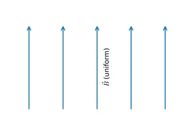
The magnetic field in a given region is uniform. Draw a diagram to represent it.
Figure
Figure

Solution

For a magnetic field to be uniform, the magnetic induction $$\vec{B}$$ must have the same magnitude and the same direction at every point in the region. In diagrams, magnetic field lines are drawn so that

  • the spacing between adjacent lines indicates the strength of the field (closer → stronger);
  • arrow-heads on the lines give the direction of $$\vec{B}$$.

Therefore, a uniform magnetic field is shown by a set of straight, parallel, equally-spaced lines all carrying arrow-heads in the same direction.

How to draw it:

  1. Draw 5 – 6 straight horizontal (or vertical) lines that are perfectly parallel to each other.
  2. Keep the gap between any two neighbouring lines the same throughout.
  3. Put arrow-heads on every line pointing, say, from left to right (or bottom to top). All arrows must point the same way.

This picture conveys that at every point in the shaded region the magnetic field vector $$\vec{B}$$ has

  • identical magnitude (equal spacing), and
  • identical direction (parallel lines with identical arrow-heads).

Such a diagram is the standard representation of a uniform magnetic field in physics.

Answer

Draw several straight, parallel, equally-spaced lines with arrow-heads all pointing in the same direction; these lines represent a uniform magnetic field.

3

Choose the correct option.

The magnetic field inside a long straight solenoid-carrying current

  1. is zero.
  2. decreases as we move towards its end.
  3. increases as we move towards its end.
  4. is the same at all points.

Solution

The strength of the magnetic field $$B$$ inside a long, straight, closely wound solenoid can be found from Ampere’s circuital law.

Consider a rectangular amperian loop that runs partly through the interior of the solenoid (length $$\\ell$$) and partly outside (where the field is negligible). For this loop

$$\oint \vec{B}\cdot d\vec{l}=B\,\ell$$

The line integral equals $$\mu_0$$ times the net current enclosed by the loop. If the solenoid has $$n$$ turns per unit length and carries current $$I$$, the enclosed current equals $$n\ell I$$. Therefore,

$$B\,\ell = \mu_0 n\ell I \;\;\Rightarrow\;\; B = \mu_0 n I$$

Important points:

  • $$\mu_0$$ (permeability of free space), $$n$$ (turns per unit length) and $$I$$ (current) are constants for a given solenoid in a given experiment.
  • The expression $$B = \mu_0 n I$$ contains no term that depends on the position inside the solenoid (provided we stay well away from the ends).

Hence the magnetic field is uniform—the same at every point inside a sufficiently long solenoid.

Therefore, the correct option is:

(d) is the same at all points.

Answer

(d) is the same at all points.

Example 12.2

Example 12.2

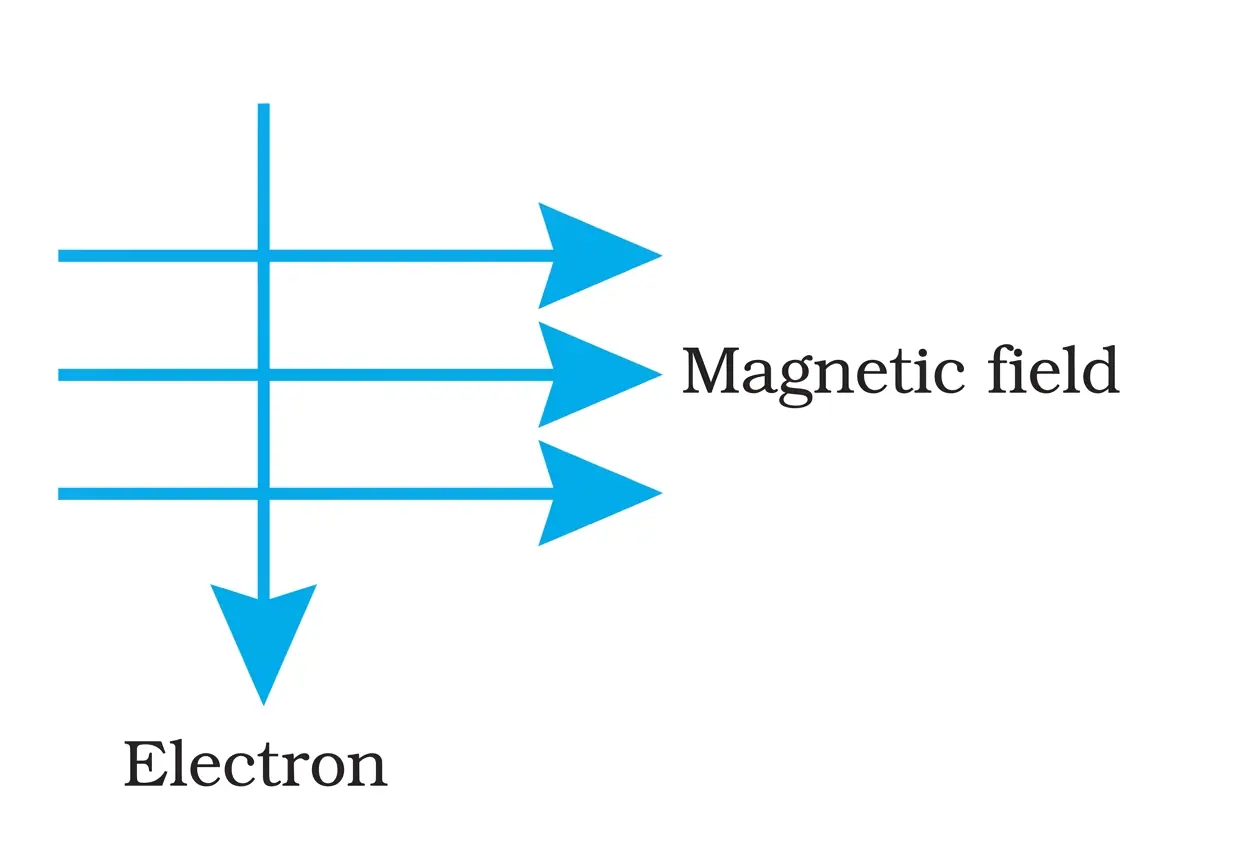
An electron enters a magnetic field at right angles to it, as shown in Fig. 12.14. The direction of force acting on the electron will be

  1. to the right.
  2. to the left.
  3. out of the page.
  4. into the page.
Fig. 12.14
Fig. 12.14

Solution

Step 1  Interpret the directions shown in Fig. 12.14
In the textbook diagram the magnetic field $$\vec B$$ is represented by dots ( • ) coming out of the page, while the velocity $$\vec v$$ of the electron is upward along the page (towards the top edge). Thus, in Cartesian symbols
$$\vec v = v\,\hat{j},\qquad \vec B = B\,\hat{k}$$

Step 2  Use the force formula on a moving charge
The magnetic force on a charge $$q$$ moving with velocity $$\vec v$$ in a magnetic field $$\vec B$$ is
$$\vec F = q\,(\vec v \times \vec B).$$

Step 3  Evaluate the cross-product
$$\vec v \times \vec B = (v\,\hat{j}) \times (B\,\hat{k}) = vB\,(\hat{j} \times \hat{k}) = vB\,\hat{i}.$$
This result points towards the right side of the page ( +$$\hat{i}$$ direction).

Step 4  Insert the charge of an electron
For an electron, $$q = -e$$ (negative). Hence
$$\vec F = (-e)\,(vB\,\hat{i}) = -e vB\,\hat{i},$$
which is along −$$\hat{i}$$, that is, towards the left side of the page.

Step 5  Choose the correct option
The magnetic force acts to the left, so the correct choice is (b).

Answer

(b) to the left.

Intext Questions (Page 203)

1

Which of the following property of a proton can change while it moves freely in a magnetic field? (There may be more than one correct answer.)

  1. mass
  2. speed
  3. velocity
  4. momentum

Solution

Given: A proton is allowed to move freely in a magnetic field (no electric field present).

Magnetic force on a moving charge
When a charge $$q$$ with velocity $$\vec v$$ enters a magnetic field $$\vec B$$, the magnetic (Lorentz) force on it is

$$\vec F = q\,(\vec v \times \vec B).$$

The vector product $$\vec v \times \vec B$$ is always perpendicular to $$\vec v$$. Therefore,

1. $$\vec F \perp \vec v$$ at every instant.
2. The work done per unit time (power) by the magnetic force is

$$P = \vec F \cdot \vec v = 0,$$

because the dot-product of two perpendicular vectors is zero.

Consequences

  • Kinetic energy $$\bigl(\tfrac12 m v^2\bigr)$$ is unchanged: the force does no work.
  • Thus the speed (magnitude of velocity) $$v$$ remains constant.
  • The direction of $$\vec v$$ continuously changes (the path is a circle or helix), so the velocity vector changes.
  • Momentum is $$\vec p = m\vec v.$$(Intrinsic) mass $$m$$ stays constant, but since $$\vec v$$ changes direction, $$\vec p$$ also changes.

Property–wise verdict

PropertyChanges?Reason
(a) MassNoIntrinsic to proton, unaffected by magnetic field.
(b) SpeedNoMagnetic force does no work ⇒ kinetic energy & $$|\vec v|$$ remain constant.
(c) Velocity (vector)YesDirection of motion keeps changing.
(d) MomentumYes$$\vec p = m\vec v;$$ magnitude fixed, direction changes.

Hence only options (c) and (d) can change.

Answer

(c) and (d)

2 In Activity 12.7, how do we think the displacement of rod AB will be affected if (i) current in rod AB is increased; (ii) a stronger horse-shoe magnet is used; and (iii) length of the rod AB is increased?

Solution

Known principle

A straight conductor carrying current $$I$$ and placed in a magnetic field of induction $$\vec{B}$$ experiences a force

$$ \vec{F}=I (\vec{L}\times\vec{B}) $$

When the conductor is perpendicular to the field (as in Activity 12.7), $$\theta = 90^{\circ}$$, so

$$ F = I L B \sin 90^{\circ}=I L B $$

The mechanical displacement of the rod AB is produced by this force; the larger the force, the greater the displacement. Hence we simply have to see how the product $$I L B$$ changes in each situation.

(i) Current in AB increased

  • In the formula, $$F \propto I$$.
  • If $$I$$ is made larger, $$F$$ increases in the same proportion.
  • A larger force pushes the rod further, so the displacement increases.

(ii) A stronger horse-shoe magnet used

  • A stronger magnet means a larger magnetic field magnitude $$B$$ between the poles.
  • Since $$F \propto B$$, the force increases.
  • Consequently, the rod is displaced through a greater distance.

(iii) Length of rod AB increased

  • Only the portion of the rod lying inside the field contributes; making this length $$L$$ bigger makes $$F \propto L$$ larger.
  • The increased force again produces a larger displacement of the rod.

Conclusion

In every case—higher current, stronger magnet, or longer rod—the magnetic force acting on AB becomes larger, so the rod is pushed farther from its initial position.

Answer

The rod will be displaced through a larger distance in all three cases: (i) when the current is increased, (ii) when a stronger horse-shoe magnet is used, and (iii) when the length of the rod within the field is increased.

3

A positively-charged particle (alpha-particle) projected towards west is deflected towards north by a magnetic field. The direction of magnetic field is

  1. towards south
  2. towards east
  3. downward
  4. upward

Solution

Given data

  • The charged particle is an alpha-particle; hence its charge $$q$$ is positive.
  • Initial velocity $$\vec v$$: towards West.
  • Magnetic force (deflection) $$\vec F$$: towards North.

Principle used

For a charged particle moving in a magnetic field, the force is given by the vector product

$$\vec F = q\,(\vec v \times \vec B)$$

Because $$q>0$$ (positive charge), the direction of $$\vec F$$ is the same as that of $$\vec v \times \vec B$$. We therefore have to find a vector $$\vec B$$ such that

$$\vec v \times \vec B = \text{towards North.}$$

Choosing a coordinate frame

DirectionAxis
East$$+x$$
North$$+y$$
Upward (out of the ground)$$+z$$

Consequently,

  • Towards West  $$\bigl(\text{opposite of East}\bigr) \;\Rightarrow\; \vec v = -\hat\imath.$$
  • Towards North  $$\Rightarrow\; \vec F = +\hat\jmath.$$

Determining \(\vec B\)

Let us test the upward direction, $$\vec B = +\hat k$$ (along $$+z$$):

$$\vec v \times \vec B = \bigl(-\hat\imath\bigr) \times \hat k.$$

Recall the right-hand rule (or the standard order of cross products):

$$\hat\imath \times \hat k = -\hat\jmath \;\Rightarrow\; \bigl(-\hat\imath\bigr) \times \hat k = +\hat\jmath.$$

Thus, with $$\vec B$$ pointing upward, $$\vec v \times \vec B$$ is indeed towards $$+y$$ (North), exactly the required force direction.

Conclusion

The magnetic field must be directed upward.

Hence, the correct option is (d).

Answer

(d) upward

Intext Questions (Page 205)

1 Name two safety measures commonly used in electric circuits and appliances.

Solution

Step 1 · Identify the requirement
Domestic wiring has to protect (a) the appliances and (b) the user from accidental overheating or electric shock.

Step 2 · List safety devices / techniques

  • Fuse (or MCB)
    A fuse is a short piece of wire with a low melting point connected in series with the live conductor. If the current exceeds the rated value, the wire melts and breaks the circuit, thereby preventing $$I^2R$$ heating that could cause fire. Modern houses often use an MCB (Miniature Circuit Breaker) that opens the circuit electromagnetically but serves the same purpose.
  • Earthing (Earth wire)
    Every metal-cased appliance is connected to the earth pin of a three-pin plug and, through it, to a thick copper strip buried deep in moist soil. If the live wire accidentally touches the metal body, the leakage current is diverted to the ground through the low-resistance earth wire, keeping the potential of the appliance near $$0\;\text{V}$$ and protecting the user from shock.

Conclusion
The two common safety measures are therefore (i) use of a fuse/MCB and (ii) proper earthing of circuits and appliances.

Answer

Use of a fuse (or MCB) and proper earthing.

2 An electric oven of 2 kW power rating is operated in a domestic electric circuit (220 V) that has a current rating of 5 A. What result do you expect? Explain.

Solution

Given data

  • Power rating of the oven, $$P = 2\,\text{kW} = 2000\,\text{W}$$
  • Mains voltage, $$V = 220\,\text{V}$$
  • Current rating of the domestic circuit, $$I_{\text{max}} = 5\,\text{A}$$

Step 1 : Calculate the current required by the oven

The relation between power, voltage and current is

$$P = V I$$

Therefore, the current drawn by the oven is

$$I = \frac{P}{V}$$

Substituting the given values :

$$I = \frac{2000\,\text{W}}{220\,\text{V}}$$

$$I = 9.09\,\text{A}\;(\text{approximately})$$

Step 2 : Compare with the circuit rating

The oven needs about $$9.1\,\text{A}$$, but the circuit can safely supply only up to $$5\,\text{A}$$.

Since $$9.1\,\text{A} > 5\,\text{A}$$, operating the oven will cause an over-current.

Step 3 : Expected result

  • The fuse (or MCB) in the domestic circuit will blow/trip to protect the wiring.
  • As a consequence, the oven will switch off and the circuit will be interrupted.

Conclusion

Trying to run a 2 kW oven on a 5 A, 220 V circuit will overload the circuit and the protective fuse will melt (or the MCB will trip) immediately.

Answer

The oven would draw about $$9\,\text{A}$$ (> 5 A); hence the circuit is overloaded and the fuse/MCB will cut off the supply.

3 What precaution should be taken to avoid the overloading of domestic electric circuits?

Solution

Concept of over-loading
Over-loading occurs when the current drawn by the appliances connected in a branch becomes larger than the current rating of that branch. If the supply voltage of the mains is $$V = 220\;\text{V}$$ and we suddenly plug in several devices whose total power consumption is $$P_{\text{tot}}$$, the current through the branch becomes

$$I = \frac{P_{\text{tot}}}{V}\;.$$

If this current $$I$$ exceeds the current rating $$I_{\max}$$ (fixed by the fuse or by the safe current-carrying capacity of the wires), the wires over-heat, the insulation may melt and a fire hazard is created. Hence we must limit the total current drawn from any one circuit.

Precautions to avoid over-loading

  • Do not connect too many high-power appliances (iron, heater, geyser, microwave, etc.) to a single socket or to a single branch circuit at the same time, because this raises $$P_{\text{tot}}$$ and hence $$I$$ beyond the safe value.
  • Use fuses or miniature circuit breakers (MCBs) of the correct current rating in every circuit so that the circuit is automatically opened if $$I$$ accidentally exceeds $$I_{\max}$$.
  • Use wires of proper thickness (low resistance) so that they can safely carry the rated current without excessive heating.

If these simple precautions are followed, the current in any domestic circuit remains within safe limits and over-loading is avoided.

Answer

Avoid connecting many high-power appliances to one socket at the same time and fit each circuit with a properly rated fuse/MCB; this keeps the current within the safe limit and prevents over-loading.

Exercises

1

Which of the following correctly describes the magnetic field near a long straight wire?

  1. The field consists of straight lines perpendicular to the wire.
  2. The field consists of straight lines parallel to the wire.
  3. The field consists of radial lines originating from the wire.
  4. The field consists of concentric circles centred on the wire.

Solution

Step 1 : Recall the experimental fact
Following Oersted’s discovery, a straight conductor carrying current was placed vertically through a horizontal cardboard sheet sprinkled with iron filings. When current flowed, the filings arranged themselves in closed circular patterns around the wire. This shows that magnetic field lines form closed concentric circles centred on the wire.

Step 2 : Apply the Right-Hand Thumb Rule
Point the right-hand thumb in the direction of conventional current $$I$$ (from positive to negative terminal). The curled fingers then point along the direction of the magnetic field lines $$\vec B$$. Because the fingers wrap round the thumb, the field at every point traces a circle around the wire; each circle has the wire as its centre and lies in a plane perpendicular to the wire.

Step 3 : Check the options

  • (a) Straight lines perpendicular to the wire  →  Incorrect; field lines are not straight.
  • (b) Straight lines parallel to the wire  →  Incorrect; experiment shows circular pattern.
  • (c) Radial lines originating from the wire  →  Incorrect; field lines do not radiate outward.
  • (d) Concentric circles centred on the wire  →  Correct; matches both experiment and the right-hand thumb rule.

Conclusion
The magnetic field near a long straight current-carrying wire consists of concentric circles centred on the wire.

Answer

(d)

2

At the time of short circuit, the current in the circuit

  1. reduces substantially.
  2. does not change.
  3. increases heavily.
  4. vary continuously.

Solution

Concept recalled
Ohm’s Law gives the relation between current $$I$$, potential difference $$V$$ and resistance $$R$$ of a closed conducting path:

$$I = \frac{V}{R}$$

What happens in a short-circuit?
A short circuit occurs when the live wire and the neutral wire (or the positive and negative terminals) come into direct contact, providing an almost resistance-free path. In that situation:

  • The resistance of the path falls to a value that is very close to $$0\,\Omega$$ (although never exactly zero in practice).

Effect on current
Substituting a very small resistance $$R_{\text{short}} \approx 0$$ in Ohm’s Law:

$$I_{\text{short}} = \frac{V}{R_{\text{short}}} \;\Rightarrow\; I_{\text{short}} \text{ becomes a very large number}$$.

Thus, at the moment of short circuit, the current in the circuit rises sharply to a very high value.

Choosing the correct option

  1. Current reduces substantially – incorrect.
  2. Current does not change – incorrect.
  3. Current increases heavily – correct.
  4. Current varies continuously – not the characteristic feature.

Therefore, the right choice is option (c).

Answer

(c) increases heavily

3 State whether the following statements are true or false.

(a) The field at the centre of a long circular coil carrying current will be parallel straight lines.

Solution

Concept recalled
The magnetic field inside a long current-carrying solenoid (which may also be described as a long circular coil) is uniform. The field lines run parallel to one another and to the axis of the solenoid; they are essentially straight within the central region.

Reasoning
Because each turn of the coil behaves like a circular loop, the superposition of the fields of many closely-spaced turns produces a nearly constant field $$\mathbf B$$ in the interior. The field lines there neither diverge nor curve; they take the shortest path—straight and parallel lines—along the length of the solenoid.

Conclusion
The description given in the statement matches this behaviour.

Answer

True

(b) A wire with a green insulation is usually the live wire of an electric supply.

Solution

Fact from domestic wiring
Standard colour code for a three-core electric cable:

  • Live (phase/hot) wire → usually red (old code) or brown (new code)
  • Neutral wire → black (old code) or blue (new code)
  • Earth (safety/ground) wire → green or green-with-yellow stripe

Reasoning
Since a green-insulated conductor is assigned to the earth connection, not to the live conductor, calling it the live wire is incorrect.

Answer

False

4 List two methods of producing magnetic fields.

Solution

The earth and almost every magnet we come across tell us that a magnetic field can exist even without electricity; Oersted’s experiment, on the other hand, showed that an electric current can also create a magnetic field. Thus, at Class 10 level we recognise two independent ways of setting up a magnetic field around a region.

  1. By a permanent magnet (magnetisation of matter)

    A bar magnet, a horseshoe magnet or even the earth itself produces a magnetic field by virtue of the alignment of atomic magnetic moments inside the material. Outside the magnet the field lines start from the north pole and return to the south pole, forming closed loops. The strength and shape of the field depend on the material and its geometry; no electric current is required once the magnet has been made.

  2. By passing an electric current through a conductor (electromagnetism)
    • Straight current‐carrying wire: Oersted found that a compass needle placed near a straight wire deflects when the wire carries current. For a long straight wire the magnitude of the magnetic field at a perpendicular distance $$r$$ is given by $$B = \frac{\mu_0 I}{2\pi r}$$, where $$I$$ is the current and $$\mu_0$$ the permeability of free space.
    • Circular coil or solenoid: If the same wire is bent into $$n$$ turns of radius $$R$$, the field at the centre becomes $$B = \frac{\mu_0 n I}{2R}$$. In a long solenoid of $$n$$ turns per unit length carrying current $$I$$, the interior field is nearly uniform and equals $$B = \mu_0 n I$$. Insertion of a soft‐iron core multiplies the field tremendously, giving a powerful electromagnet.

Therefore, the two basic methods are (i) using permanent magnets and (ii) using electric current through a conductor (i.e. an electromagnet).

Answer

(i) By using a permanent magnet.
(ii) By passing an electric current through a conductor (electromagnet).

5 When is the force experienced by a current-carrying conductor placed in a magnetic field largest?

Solution

For a straight conductor of length L carrying a current I in a uniform magnetic field of induction B, the magnetic force is given by the vector product

$$\vec F = I\,(\vec L \times \vec B)$$

Hence the magnitude of the force is

$$F = I L B \sin \theta$$

where $$\theta$$ is the angle between the direction of current (along $$\vec L$$) and the magnetic field $$\vec B$$.

  1. The quantities $$I$$, $$L$$ and $$B$$ are fixed for the given conductor and field.
  2. The factor that can vary is $$\sin \theta$$, whose maximum possible value is 1.

Therefore,

$$F_{\max}=I L B \times 1$$

when $$\sin \theta=1 \;\Longrightarrow\; \theta=90^{\circ}$$.

Thus, the force is largest when the conductor is oriented perpendicular to the direction of the magnetic field lines.

Answer

When the conductor is at $$90^{\circ}$$ (perpendicular) to the magnetic field lines, i.e. $$\theta=90^{\circ}$$ so that $$\sin\theta=1$$ and the force $$F=ILB\sin\theta$$ becomes maximum.

6 Imagine that you are sitting in a chamber with your back to one wall. An electron beam, moving horizontally from back wall towards the front wall, is deflected by a strong magnetic field to your right side. What is the direction of magnetic field?

Solution

Given

  • You sit with your back to the rear wall and face the front wall.
  • An electron beam travels horizontally from the rear (back) wall towards the front wall.
  • The beam is deflected towards your right side.

Step 1 – Choose axes

  • Facing direction (front wall)  →  $$+z$$-axis.
  • Your right side  →  $$+x$$-axis.
  • Upward (towards the ceiling)  →  $$+y$$-axis.

Step 2 – Velocity of the electrons

Electrons move from back to front, so $$\vec v_{\mathrm e}=+v\,\hat z$$.

Step 3 – Magnetic force on an electron

The Lorentz force is $$\vec F=q\,\vec v\times\vec B$$. For an electron, $$q=-e$$, hence

$$\vec F_{\mathrm e}=(-e)(\vec v_{\mathrm e}\times\vec B).$$

The observed deflection is to the right: $$\vec F_{\mathrm e}=+F\,\hat x$$.

Step 4 – Determine $$\vec B$$

Substituting directions:

$$+F\,\hat x = (-e)(+v\,\hat z \times \vec B).$$

Divide by the negative constant $$-ev$$:

$$\hat z \times \vec B = -\hat x.$$

Using the right-hand rule, $$\hat z \times \hat y = -\hat x$$, so

$$\vec B = B\,\hat y,$$

i.e. $$\vec B$$ is along the $$+y$$-axis.

Step 5 – Ordinary language

The $$+y$$-axis corresponds to the vertically upward direction.

Result

The magnetic field in the chamber is vertically upward (from the floor towards the ceiling).

Answer

Vertically upward (towards the ceiling).

7 State the rule to determine the direction of a

(i) magnetic field produced around a straight conductor-carrying current.

Solution

Concept recalled
Whenever an electric current flows through a straight conductor, concentric circular magnetic-field lines are produced around the conductor. To know whether these field lines are clockwise or anticlockwise, we need a directional rule.

Rule stated and justified
The required rule is the Right-hand thumb rule (also called Maxwell’s cork-screw rule). Hold the conductor in your right hand in such a way that the thumb points along the direction of conventional current $$I$$; then the curled fingers encircling the conductor give the direction of the magnetic-field lines $$\vec B$$.

Why it works (brief)
This rule is an application of the cross-product $$d\vec B \propto I\,d\vec l \times \hat r$$ that emerges from the Biot–Savart law; the right-hand convention provides the sign of the perpendicular vector.

Answer

Use the right-hand thumb rule: thumb along the current, curled fingers give the direction of the magnetic field round the straight conductor.

(ii) force experienced by a current-carrying straight conductor placed in a magnetic field which is perpendicular to it, and

Solution

Situation recalled
A straight conductor carrying current $$I$$ is placed in a uniform magnetic field $$\vec B$$ that is perpendicular to the length of the conductor. The conductor experiences a mechanical force $$\vec F$$ at right angles to both $$\vec B$$ and $$I$$.

Rule stated
The direction of this force is given by Fleming’s left-hand rule:

  • Stretch the forefinger, the middle finger and the thumb of your left hand so that they are mutually perpendicular.
  • Arrange them so that
     • the forefinger points in the direction of the magnetic field $$\vec B$$ (north to south),
     • the middle finger points in the direction of the current $$I$$ (positive to negative).
  • Then the thumb gives the direction of the force (or motion) $$\vec F$$ on the conductor.

Vector explanation (optional)
The rule provides the orientation of the cross-product $$\vec F = I(\vec l \times \vec B)$$, whose sense is fixed by the left-hand convention used for charges moving in external magnetic fields.

Answer

Apply Fleming’s left-hand rule: with forefinger along the magnetic field and middle finger along the current, the thumb points in the direction of the force on the conductor.

(iii) current induced in a coil due to its rotation in a magnetic field.

Solution

Physical context
When a coil or conductor moves (or is rotated) in a magnetic field, an emf and hence a current is induced in it. The direction of this induced current has to be found.

Rule stated
The direction is given by Fleming’s right-hand rule:

  • Stretch the forefinger, middle finger and thumb of your right hand so that each is perpendicular to the other two.
  • Orient the hand so that
     • the thumb points in the direction of motion (or push) of the conductor relative to the field,
     • the forefinger points in the direction of the magnetic field $$\vec B$$ (N→S).
  • Then the middle finger gives the direction of the induced current $$I_{\text{ind}}$$ in the conductor/coil.

Underlying principle
This is consistent with Lenz’s law and Faraday’s law, the right-hand orientation providing the sign of the induced emf $$\mathcal E = -\dfrac{d\Phi}{dt}$$.

Answer

Use Fleming’s right-hand rule: with thumb along the motion of the conductor and forefinger along the magnetic field, the middle finger gives the direction of the induced current in the rotating coil.

8 When does an electric short circuit occur?

Solution

Concept involved : Ohm’s law relates the current $$I$$ flowing through a conductor to the potential difference $$V$$ applied across it and its resistance $$R$$ by the relation $$I = \frac{V}{R}$$. If the resistance of the path suddenly becomes extremely small, the current rises sharply.

Normal domestic circuit : In a lighting or power circuit the live wire carries the high potential, while the neutral wire is at zero potential. All appliances (lamp, fan, heater, etc.) are connected between these two conductors, so the current first passes through the appliance’s internal resistance before returning by the neutral wire.

How a short-circuit happens :

  1. If the plastic insulation on the live and neutral conductors is damaged or melts, or if the two wires are joined accidentally, they may touch each other directly.
  2. The current now bypasses the appliance and flows through the metallic conductors themselves, whose resistance is extremely small, practically $$R \approx 0\,\Omega$$.
  3. Because $$R$$ is almost zero, Ohm’s law gives a huge current $$I = \frac{V}{R} \to \text{very large}$$.

The sudden flow of an excessively large current is called an electric short circuit. It may overheat the wiring and produce fire unless a fuse or an MCB disconnects the supply immediately.

Typical causes (for completeness)

  • Frayed or cracked insulation.
  • Loose connections allowing the wires to touch.
  • Insertion of a conducting object (e.g. a nail) that bridges the two wires.

Thus, an electric short circuit occurs whenever the live and neutral (or positive and negative) conductors are connected directly together, providing a path of negligibly small resistance.

Answer

An electric short circuit occurs when the live and neutral conductors come into direct contact, giving the current a path of almost zero resistance; the resulting very large current is called a short-circuit current.

9 What is the function of an earth wire? Why is it necessary to earth metallic appliances?

Solution

Step 1 ‒ Recall the three wires of a household circuit

  • The live (or phase) wire is at a potential of about $$+220\,\text{V}$$ with respect to the ground.
  • The neutral wire is at $$0\,\text{V}$$ because it is directly connected to the earth at the distribution transformer.
  • The earth wire is an additional copper conductor that is also maintained at the earth potential $$0\,\text{V}$$, but it is connected only to the metallic body of an appliance and not to its working circuit.

Step 2 ‒ Function of the earth wire

The earth wire offers a path of very low resistance (typically a fraction of an ohm) between the metallic case and the ground. If, owing to wear of insulation or some defect, the live wire touches the metallic case, the potential of the case would instantly try to rise from $$0\,\text{V}$$ to $$+220\,\text{V}$$. Because of the earth wire, a large current $$I$$ now flows

$$I = \frac{V}{R_{\text{earth}}}$$

where $$V \approx 220\,\text{V}$$ and $$R_{\text{earth}}$$ is very small. This large current either

  • immediately blows the fuse or trips the circuit-breaker, disconnecting the supply, and/or
  • keeps the case at nearly $$0\,\text{V}$$ so a person touching it does not receive an electric shock.

Step 3 ‒ Why metallic appliances must be earthed

  1. Most domestic gadgets (electric iron, refrigerator, heater, etc.) have an outer metallic body for mechanical strength and heat conduction.
  2. If the insulation inside fails, the live conductor may come in contact with this body. Without earthing, the whole body would attain live potential; anyone touching it would then complete a circuit to the ground through his or her body and suffer a severe shock.
  3. Earthing keeps the body at ground potential and ensures that the excess current chooses the path of least resistance—the earth wire—rather than the human body, which has a much higher resistance (of the order of $$10^3$$–$$10^5\,\Omega$$).

Final point

Thus, the earth wire is a vital safety feature: it prevents the metallic case from becoming live and causes the protective fuse or MCB to operate quickly, safeguarding both the user and the appliance.

Answer

The earth wire provides a direct, very low-resistance path from the metallic body of an appliance to the ground, keeping that body at $$0\,\text{V}$$. Metallic appliances are earthed so that, if the live conductor accidentally touches the case, the large current that flows to earth blows the fuse/trips the MCB and prevents the user from getting an electric shock.

NCERT Solutions for Class 10
Maths
NCERT Solutions for Class 10 Maths
Chapter-wise step-by-step
solutions with explanations
explore solutions Maths bg
Science
NCERT Solutions for Class 10 Science
Chapter-wise step-by-step
solutions with explanations
explore solutions Science bg

Frequently Asked Questions

50,000+ JEE Students Trusted Our Score Calculator

Predict your JEE Main percentile, rank & performance in seconds