Join WhatsApp Icon JEE WhatsApp Group
NCERT Solutions for Class 10 Science

Chapter 11: Electricity

Download Solutions PDF
Daily JEE Updates, Tips & Important Alerts
Join 30,000+ students and stay updated with JEE notifications and preparation insights.
Join Now!
Free PDF
Complete NCERT Solution PDF for Chapter 11: Electricity

NCERT Solutions For Class 10 Science Chapter 11 Electricity helps students understand the principles of electric current, circuits, resistance, and electrical energy. The page provides detailed NCERT Solutions that explain important concepts such as Ohm’s law, electric potential, resistance, series and parallel combinations, and power calculations. NCERT Solutions For Class 10 Science guide students through numerical problems and theoretical concepts with clear step-by-step methods. The chapter builds essential knowledge about how electricity flows and how electrical devices function. These solutions are designed to help students practise questions, strengthen conceptual understanding, and prepare for board examinations. Students can access the chapter PDF for revision and regular practice. The structured explanations make electricity concepts easier to understand and help students solve numerical problems confidently.

Download Solutions PDF

Examples

Example 11.1 A current of $$0.5 \, \mathrm{A}$$ is drawn by a filament of an electric bulb for 10 minutes. Find the amount of electric charge that flows through the circuit.

Solution

The relationship between electric current $$I$$, time $$t$$ and the corresponding charge $$Q$$ that flows is

$$I = \dfrac{Q}{t}$$

Re-arranging for the charge,

$$Q = I\,t$$

Step 1: Convert the given time to seconds.

Given time = 10 minutes

$$t = 10 \times 60 \; \text{seconds} = 600 \; \text{s}$$

Step 2: Substitute the values of $$I$$ and $$t$$ in the formula.

Current $$I = 0.5 \; \text{A}$$,   Time $$t = 600 \; \text{s}$$

$$\begin{aligned} Q &= I\,t \\[4pt] &= 0.5\;\text{A} \times 600\;\text{s} \\[4pt] &= 300 \; \text{C} \end{aligned}$$

Therefore, the amount of charge that flows through the circuit is $$300\,\text{C}$$.

Answer

$$Q = 300\;\text{C}$$

Example 11.2 How much work is done in moving a charge of $$2 \, \mathrm{C}$$ across two points having a potential difference $$12 \, \mathrm{V}$$?

Solution

Given data

  • Charge moved, $$q = 2 \; \mathrm{C}$$
  • Potential difference between the two points, $$V = 12 \; \mathrm{V}$$

Formula used

The work $$W$$ required to move a charge $$q$$ through a potential difference $$V$$ is

$$W = q \, V$$

Substitution

$$W = (2 \; \mathrm{C}) imes (12 \; \mathrm{V})$$

Calculation

$$W = 24 \; \mathrm{J}$$

Conclusion

The work done in moving the charge is $$24 \; \mathrm{J}$$.

Answer

$$24 \, \mathrm{J}$$

Example 11.3

(a) How much current will an electric bulb draw from a $$220 \, \mathrm{V}$$ source, if the resistance of the bulb filament is $$1200 \, \Omega$$?

(b) How much current will an electric heater coil draw from a $$220 \, \mathrm{V}$$ source, if the resistance of the heater coil is $$100 \, \Omega$$?

(a) How much current will an electric bulb draw from a $$220 \, \mathrm{V}$$ source, if the resistance of the bulb filament is $$1200 \, \Omega$$?

Solution

We use Ohm’s law, which relates current $$I$$, potential difference $$V$$ and resistance $$R$$ by

$$I = \frac{V}{R}$$

Given data:
$$V = 220\,\text{V}$$
$$R = 1200\,\Omega$$

Substituting:

$$I = \frac{220\,\text{V}}{1200\,\Omega}$$

Simplify the fraction step by step:

$$I = \frac{22}{120}\,\text{A}$$ (dividing numerator and denominator by 10)

$$I = \frac{11}{60}\,\text{A}$$

$$I \approx 0.183\,\text{A}$$

Therefore, the bulb draws approximately $$0.18\,\text{A}$$ of current.

Answer

(a) $I \approx 0.18\,\text{A}$

(b) How much current will an electric heater coil draw from a $$220 \, \mathrm{V}$$ source, if the resistance of the heater coil is $$100 \, \Omega$$?

Solution

Again apply Ohm’s law:

$$I = \frac{V}{R}$$

Given data:
$$V = 220\,\text{V}$$
$$R = 100\,\Omega$$

Substituting:

$$I = \frac{220\,\text{V}}{100\,\Omega}$$

$$I = 2.2\,\text{A}$$

Thus, the heater coil draws $$2.2\,\text{A}$$ of current.

Answer

(b) $I = 2.2\,\text{A}$

Example 11.4 The potential difference between the terminals of an electric heater is $$60 \, \mathrm{V}$$ when it draws a current of $$4 \, \mathrm{A}$$ from the source. What current will the heater draw if the potential difference is increased to $$120 \, \mathrm{V}$$?

Solution

Given data

  • Initial potential difference across the heater, $$V_1 = 60 \, \text{V}$$
  • Current drawn at this potential difference, $$I_1 = 4 \, \text{A}$$
  • New potential difference, $$V_2 = 120 \, \text{V}$$

The heater is assumed to be ohmic, so its resistance stays constant. Using Ohm’s law, $$V = I R$$, find the resistance first.

$$R = \frac{V_1}{I_1} = \frac{60 \; \text{V}}{4 \; \text{A}} = 15 \; \Omega$$

Now calculate the current at the higher potential difference:

$$I_2 = \frac{V_2}{R} = \frac{120 \; \text{V}}{15 \; \Omega} = 8 \; \text{A}$$

Therefore, the heater will draw a current of $$8 \; \text{A}$$ when the potential difference is $$120 \; \text{V}$$.

Answer

$$I = 8 \, \text{A}$$

Example 11.5 Resistance of a metal wire of length $$1 \, \mathrm{m}$$ is $$26 \, \Omega$$ at $$20\,°\mathrm{C}$$. If the diameter of the wire is $$0.3 \, \mathrm{mm}$$, what will be the resistivity of the metal at that temperature? Using Table 11.2, predict the material of the wire.

Solution

Given data

  • Resistance of the wire: $$R = 26\;\Omega$$
  • Length of the wire: $$l = 1\;\text{m}$$
  • Diameter of the wire: $$d = 0.3\;\text{mm}$$
  • Temperature: $$20\,{}^{\circ}\text{C}$$ (table values are quoted for the same temperature)

1. Convert the diameter to radius in metres

$$r = \frac{d}{2} = \frac{0.3\;\text{mm}}{2} = 0.15\;\text{mm}$$

Since $$1\;\text{mm}=10^{-3}\;\text{m}$$,

$$r = 0.15\times10^{-3}\;\text{m}=1.5\times10^{-4}\;\text{m}$$

2. Find the cross-sectional area

$$A = \pi r^{2} = \pi(1.5\times10^{-4}\;\text{m})^{2}$$

$$A = \pi\times2.25\times10^{-8}\;\text{m}^{2} \;\approx\; 7.07\times10^{-8}\;\text{m}^{2}$$

3. Use the relation between resistance and resistivity

The defining equation is $$R = \rho\,\dfrac{l}{A} \;\Rightarrow\; \rho = R\,\dfrac{A}{l}$$

Substituting the known values (with $$l = 1\;\text{m}$$):

$$\rho = 26\;\Omega\;\times\;7.07\times10^{-8}\;\text{m}^{2}$$

$$\rho \approx 1.84\times10^{-6}\;\Omega\,\text{m}$$

4. Identify the material using Table 11.2

Typical resistivities at $$20\,{}^{\circ}\text{C}$$ (from Table 11.2):

  • Silver: $$1.60\times10^{-8}\;\Omega\,\text{m}$$
  • Copper: $$1.62\times10^{-8}\;\Omega\,\text{m}$$
  • Aluminium: $$2.63\times10^{-8}\;\Omega\,\text{m}$$
  • Constantan: $$4.9\times10^{-7}\;\Omega\,\text{m}$$
  • Nichrome: $$1.1\times10^{-6}\;\Omega\,\text{m}$$

The calculated resistivity $$\bigl(1.8\times10^{-6}\,\Omega\text{ m}\bigr)$$ is closest to that of nichrome. (Pure metals have resistivities nearly two orders of magnitude lower.)

Result

The resistivity of the wire at $$20\,{}^{\circ}\text{C}$$ is $$\rho \approx 1.8\times10^{-6}\;\Omega\,\text{m}$$, and the material is most likely nichrome.

Answer

$$\rho \approx 1.8\times10^{-6}\;\Omega\,\text{m}$$; the wire is most likely made of nichrome.

Example 11.6 A wire of given material having length $$l$$ and area of cross-section $$A$$ has a resistance of $$4 \, \Omega$$. What would be the resistance of another wire of the same material having length $$l/2$$ and area of cross-section $$2A$$?

Solution

The resistance $$R$$ of a uniform wire is given by the relation

$$R = \rho \dfrac{l}{A}$$

where

  • $$\rho$$ = resistivity of the material (same for all wires made of this material),
  • $$l$$ = length of the wire,
  • $$A$$ = area of cross-section of the wire.

Step 1 : Express the resistivity from the first wire

For the first wire, the data are

length $$l_1 = l$$,   area $$A_1 = A$$,   resistance $$R_1 = 4\,\Omega$$.

Substituting in the formula:

$$R_1 = \rho \dfrac{l_1}{A_1} \;\Rightarrow\; 4 = \rho \dfrac{l}{A} \;\;\;\; (1)$$

Step 2 : Write the expression for the second wire

For the second wire, the data are

length $$l_2 = \dfrac{l}{2}$$,   area $$A_2 = 2A$$,   resistance to be found = $$R_2$$.

Using the same resistivity $$\rho$$:

$$R_2 = \rho \dfrac{l_2}{A_2} = \rho \dfrac{\dfrac{l}{2}}{2A}$$

Simplify the fraction:

$$R_2 = \rho \dfrac{l}{2} \times \dfrac{1}{2A} = \rho \dfrac{l}{4A}$$

Step 3 : Compare with equation (1)

From Eq. (1), $$\rho \dfrac{l}{A} = 4$$. Therefore

$$R_2 = \dfrac{1}{4}\left( \rho \dfrac{l}{A} \right) = \dfrac{1}{4} \times 4 = 1\,\Omega$$

Result

The resistance of the second wire is $$1\,\Omega$$.

Answer

$$1\,\Omega$$

Example 11.7

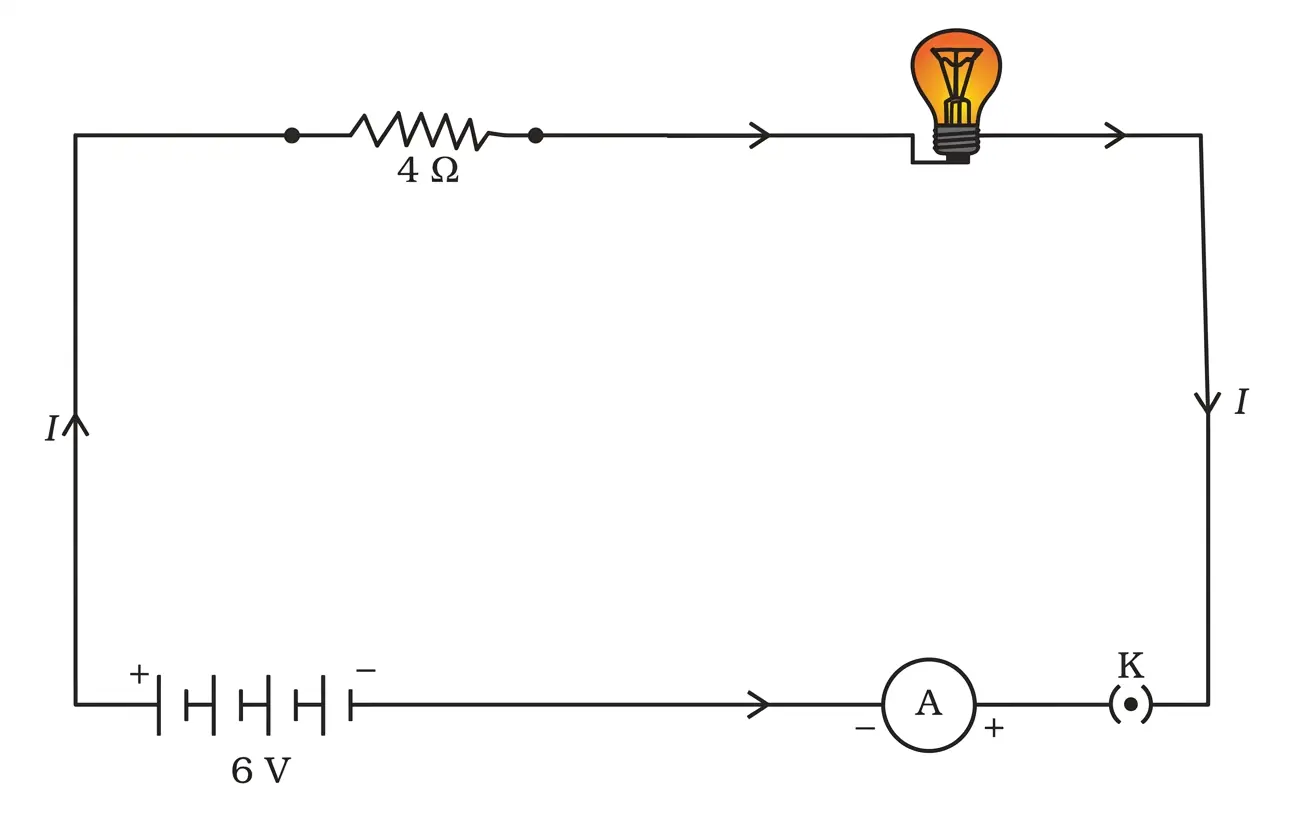
An electric lamp, whose resistance is $$20 \, \Omega$$, and a conductor of $$4 \, \Omega$$ resistance are connected to a $$6 \, \mathrm{V}$$ battery (Fig. 11.9). Calculate (a) the total resistance of the circuit, (b) the current through the circuit, and (c) the potential difference across the electric lamp and conductor.
Fig. 11.9
Fig. 11.9

Solution

Given data

  • Resistance of the electric lamp, $$R_1 = 20\,\Omega$$
  • Resistance of the conductor, $$R_2 = 4\,\Omega$$
  • EMF of the battery, $$V = 6\,\text{V}$$

The lamp and the conductor are shown in Fig. 11.9 one after the other, so they are in series.

(a) Total resistance of the circuit

For resistors in series the equivalent resistance is the sum of individual resistances:

$$R_{\text{eq}} = R_1 + R_2$$

$$R_{\text{eq}} = 20\,\Omega + 4\,\Omega = 24\,\Omega$$

(b) Current through the circuit

Using Ohm’s law, $$I = \dfrac{V}{R_{\text{eq}}}$$.

$$I = \dfrac{6\,\text{V}}{24\,\Omega} = 0.25\,\text{A}$$

So the current flowing is $$0.25\,\text{A}$$ (or $$\dfrac14\,\text{A}$$).

(c) Potential difference across each component

Again by Ohm’s law, $$V = I R$$ for each resistor.

  • Across the electric lamp:

    $$V_1 = I R_1 = 0.25\,\text{A}\times 20\,\Omega = 5\,\text{V}$$

  • Across the conductor:

    $$V_2 = I R_2 = 0.25\,\text{A}\times 4\,\Omega = 1\,\text{V}$$

The two potential differences add up to the battery emf: $$5\,\text{V} + 1\,\text{V} = 6\,\text{V}$$, confirming the calculations.

Answer

(a) $$R_{\text{eq}} = 24\,\Omega$$
(b) $$I = 0.25\,\text{A}$$
(c) Across lamp $$V_1 = 5\,\text{V}$$; across conductor $$V_2 = 1\,\text{V}$$

Example 11.8

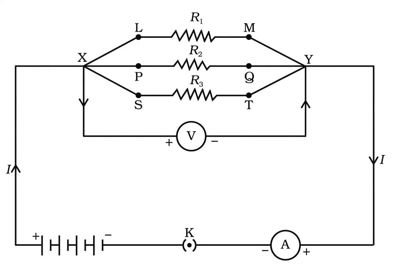
In the circuit diagram given in Fig. 11.10, suppose the resistors $$R_1$$, $$R_2$$ and $$R_3$$ have the values $$5 \, \Omega$$, $$10 \, \Omega$$, $$30 \, \Omega$$, respectively, which have been connected to a battery of $$12 \, \mathrm{V}$$. Calculate (a) the current through each resistor, (b) the total current in the circuit, and (c) the total circuit resistance.
Fig. 11.10
Fig. 11.10

Solution

The three given resistors are connected in series (as shown in Fig. 11.10). In a series circuit

  • the same current flows through every resistor, and
  • the equivalent resistance equals the sum of individual resistances.

1. Equivalent resistance

$$R_{\mathrm{eq}} = R_1 + R_2 + R_3 = 5\,\Omega + 10\,\Omega + 30\,\Omega = 45\,\Omega$$

2. Current supplied by the 12 V battery

Using Ohm’s law $$I = \dfrac{V}{R_{\mathrm{eq}}}$$,

$$I = \frac{12\,\mathrm{V}}{45\,\Omega} = 0.2667\,\mathrm{A} \approx 0.27\,\mathrm{A}$$

3. Current through each resistor

Because the resistors are in series, the same current passes through each one:

$$I_1 = I_2 = I_3 = 0.27\,\mathrm{A}$$

4. Total current in the circuit

The circuit has only one path, so

$$I_{\text{total}} = 0.27\,\mathrm{A}$$

5. Total resistance of the circuit

$$R_{\text{total}} = 45\,\Omega$$

Answer

(a) $$I_1 = I_2 = I_3 \approx 0.27\,\mathrm{A}$$
(b) Total current $$I \approx 0.27\,\mathrm{A}$$
(c) Total resistance $$R = 45\,\Omega$$

Example 11.9

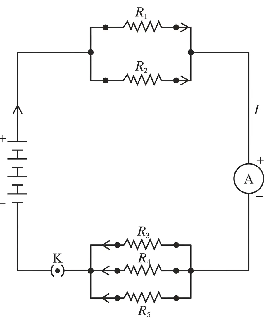
If in Fig. 11.12, $$R_1 = 10 \, \Omega$$, $$R_2 = 40 \, \Omega$$, $$R_3 = 30 \, \Omega$$, $$R_4 = 20 \, \Omega$$, $$R_5 = 60 \, \Omega$$, and a $$12 \, \mathrm{V}$$ battery is connected to the arrangement. Calculate (a) the total resistance in the circuit, and (b) the total current flowing in the circuit.
Fig. 11.12
Fig. 11.12

Solution

Interpreting Fig. 11.12
(As described in the textbook, starting from the left-hand terminal of the battery and moving clockwise)

  1. $$R_1$$ and $$R_2$$ are connected in series in the upper branch.
  2. This series combination is connected in parallel with $$R_3$$ through a vertical conductor.
  3. The resulting equivalent resistance is then connected in series with a lower branch that contains $$R_4$$ and $$R_5$$ in parallel.

The required reduction can therefore be done in three clear stages.

Step 1 – Series combination of $$R_1$$ and $$R_2$$

For resistors in series, equivalent resistance is the arithmetic sum:

$$R_{12} = R_1 + R_2 = 10\,\Omega + 40\,\Omega = 50\,\Omega$$

Step 2 – Parallel combination of $$R_{12}$$ with $$R_3$$

For two resistors in parallel,

$$\frac{1}{R_{123}} = \frac{1}{R_{12}} + \frac{1}{R_3}$$

Substituting the values,

$$\frac{1}{R_{123}} = \frac{1}{50\,\Omega} + \frac{1}{30\,\Omega}$$

$$\frac{1}{R_{123}} = \frac{30 + 50}{50 \times 30} = \frac{80}{1500}$$

$$R_{123} = \frac{1500}{80}\,\Omega = 18.75\,\Omega$$

Step 3 – Parallel combination of $$R_4$$ and $$R_5$$

Again using the parallel-resistance relation,

$$\frac{1}{R_{45}} = \frac{1}{R_4} + \frac{1}{R_5} = \frac{1}{20\,\Omega} + \frac{1}{60\,\Omega}$$

$$\frac{1}{R_{45}} = \frac{3 + 1}{60} = \frac{4}{60}$$

$$R_{45} = \frac{60}{4}\,\Omega = 15\,\Omega$$

Step 4 – Total (net) resistance of the circuit

The two equivalent resistances found in Steps 2 and 3 are in series, so

$$R_{\text{total}} = R_{123} + R_{45} = 18.75\,\Omega + 15\,\Omega = 33.75\,\Omega$$

Step 5 – Current supplied by the $$12\,\mathrm V$$ battery

Using Ohm’s law, $$I = \dfrac{V}{R}$$:

$$I = \frac{12\,\mathrm V}{33.75\,\Omega} = 0.3556\,\mathrm A \approx 0.356\,\mathrm A$$

Results

  • (a) Total resistance of the circuit: $$R_{\text{total}} = 33.75\,\Omega$$.
  • (b) Current drawn from the battery: $$I \approx 0.356\,\mathrm A$$.

Answer

(a) $$R_{\text{total}} = 33.75\,\Omega$$
(b) $$I \approx 0.356\,\mathrm A$$

Example 11.10 An electric iron consumes energy at a rate of $$840 \, \mathrm{W}$$ when heating is at the maximum rate and $$360 \, \mathrm{W}$$ when the heating is at the minimum. The voltage is $$220 \, \mathrm{V}$$. What are the current and the resistance in each case?

Solution

Given data

  • Voltage applied across the iron: $$V = 220 \, \mathrm{V}$$
  • Power at maximum heating: $$P_{\text{max}} = 840 \, \mathrm{W}$$
  • Power at minimum heating: $$P_{\text{min}} = 360 \, \mathrm{W}$$

Relevant formulae

  • Electric power: $$P = VI$$
  • Ohm’s law: $$V = IR$$
  • Hence, $$I = \dfrac{P}{V}$$ and $$R = \dfrac{V}{I} = \dfrac{V^{2}}{P}$$

Case 1 : Maximum heating

  1. Current:
    $$I_{\text{max}} = \frac{P_{\text{max}}}{V} = \frac{840}{220} \, \mathrm{A}$$
    $$I_{\text{max}} = 3.818 \, \mathrm{A} \; (\text{approximately } 3.8\, \mathrm{A})$$
  2. Resistance:
    $$R_{\text{max}} = \frac{V^{2}}{P_{\text{max}}} = \frac{(220)^2}{840} \, \Omega$$
    $$R_{\text{max}} = 57.6 \, \Omega \; (\text{approximately } 58\, \Omega)$$

Case 2 : Minimum heating

  1. Current:
    $$I_{\text{min}} = \frac{P_{\text{min}}}{V} = \frac{360}{220} \, \mathrm{A}$$
    $$I_{\text{min}} = 1.636 \, \mathrm{A} \; (\text{approximately } 1.6\, \mathrm{A})$$
  2. Resistance:
    $$R_{\text{min}} = \frac{V^{2}}{P_{\text{min}}} = \frac{(220)^2}{360} \, \Omega$$
    $$R_{\text{min}} = 134.4 \, \Omega \; (\text{approximately } 134\, \Omega)$$

Thus, when the iron is set to maximum heating it draws about $$3.8 \, \mathrm{A}$$ and its resistance is about $$58 \, \Omega$$; when set to minimum heating it draws about $$1.6 \, \mathrm{A}$$ and its resistance is about $$134 \, \Omega$$.

Answer

Maximum heating: $$I \approx 3.8\, \mathrm{A}, \; R \approx 58\, \Omega$$
Minimum heating: $$I \approx 1.6\, \mathrm{A}, \; R \approx 134\, \Omega$$

Example 11.11 $$100 \, \mathrm{J}$$ of heat is produced each second in a $$4 \, \Omega$$ resistance. Find the potential difference across the resistor.

Solution

The rate at which heat is produced equals the electrical power $$P$$ dissipated in the resistor.

Since $$100\,\text{J}$$ of heat is produced every second,

$$P = \frac{\text{energy}}{\text{time}} = \frac{100\,\text{J}}{1\,\text{s}} = 100\,\text{W}.$$

For a resistor the power–voltage–resistance relation is

$$P = \frac{V^{2}}{R}.$$

Solving for the potential difference $$V$$ gives

$$V^{2} = P R \;\;\Rightarrow\;\; V = \sqrt{P R}.$$

Substitute the given values $$P = 100\,\text{W}$$ and $$R = 4\,\Omega$$:

$$V = \sqrt{100 \times 4}\,\mathrm V = \sqrt{400}\,\mathrm V = 20\,\mathrm V.$$

Hence, the potential difference across the $$4\,\Omega$$ resistor is $$20\,\text{V}.$$

Answer

$$V = 20 \, \mathrm{V}$$

Example 11.12 An electric bulb is connected to a $$220 \, \mathrm{V}$$ generator. The current is $$0.50 \, \mathrm{A}$$. What is the power of the bulb?

Solution

Given data

  • Potential difference across the bulb: $$V = 220 \; \mathrm{V}$$
  • Current through the bulb: $$I = 0.50 \; \mathrm{A}$$

Formula used

For an electrical device, the power $$P$$ consumed is given by

$$P = V I$$

Substitution and calculation

$$P = 220 \; \mathrm{V} \times 0.50 \; \mathrm{A}$$

$$P = 110 \; \mathrm{W}$$

Result

The power rating of the bulb is $$110 \; \mathrm{W}$$.

Answer

$$P = 110 \; \mathrm{W}$$

Example 11.13 An electric refrigerator rated $$400 \, \mathrm{W}$$ operates $$8 \, \mathrm{hour/day}$$. What is the cost of the energy to operate it for 30 days at Rs $$3.00$$ per kW h?

Solution

The data given in the statement can be listed first.

  • Rated power of the refrigerator, $$P = 400\,\text{W}$$
  • Daily operating time, $$t_{\text{day}} = 8\,\text{h}$$
  • Period of use, $$n = 30\,\text{days}$$
  • Tariff (rate of electrical energy), $$R = \text{Rs }3.00 \text{ per kW h}$$

Step 1 ∙ Convert the power to kilowatts

$$P = 400\,\text{W} = \frac{400}{1000}\,\text{kW} = 0.4\,\text{kW}$$

Step 2 ∙ Find the electrical energy consumed in one day

Electrical energy $$E_{\text{day}}$$ (in kW h) is given by the product of power (in kW) and time (in h):

$$E_{\text{day}} = P\,t_{\text{day}} = 0.4\,\text{kW}\times 8\,\text{h} = 3.2\,\text{kW h}$$

Step 3 ∙ Find the electrical energy consumed in 30 days

$$E_{30} = E_{\text{day}}\times n = 3.2\,\text{kW h}\times 30 = 96\,\text{kW h}$$

Step 4 ∙ Calculate the total cost

Cost, $$C$$, is obtained by multiplying the total energy consumed by the tariff:

$$C = E_{30}\times R = 96\,\text{kW h}\times \text{Rs }3.00\,/\,\text{kW h} = \text{Rs }288$$

Therefore, the cost of operating the refrigerator for 30 days is Rs 288.

Answer

Rs 288

Intext Questions (Page 172)

1 What does an electric circuit mean?

Solution

An electric circuit is the complete, closed conducting path along which electric charges can move continuously.

To form such a path we need three essential components:

  • Source of potential difference – a cell, battery, or any other device that can maintain a steady difference in electric potential between its terminals.
  • Conducting connectors – metallic wires that join the various elements so that charge carriers (electrons in the wire) can move throughout the loop.
  • Load or circuit elements – electrical devices such as resistors, bulbs, meters, switches, etc. that are connected between the terminals of the source.

Only when the path is closed (for example, when a key or switch is turned on) does current $$I$$ flow; the moment the path becomes open or broken, current stops because charges can no longer complete the loop.

Thus, an electric circuit is the closed, continuous conducting loop that allows current to flow from the positive terminal of the source, through the external components, and back to the negative terminal.

Answer

An electric circuit is a closed, continuous conducting path that allows electric current to flow from the positive terminal of a source, through external components, and back to the negative terminal.

2 Define the unit of current.

Solution

Electric current $$I$$ is defined as the rate of flow of electric charge:

$$I = \dfrac{Q}{t}$$

Here, $$Q$$ is the charge (in coulomb, $$\mathrm{C}$$) that crosses a given cross-section of the conductor in time $$t$$ (in second, $$\mathrm{s}$$).

The SI unit of current is the ampere (symbol $$\mathrm{A}$$).

By definition:

One ampere is that constant current which transfers exactly one coulomb of charge through any cross-section of a conductor in one second.

Mathematically,

$$1\,\mathrm{A} = 1\,\mathrm{C\,s^{-1}}$$

(The more advanced scientific definition—used for precise standards—relates the ampere to the force between parallel conductors, but for Class 10 the coulomb-per-second definition is sufficient.)

Answer

One ampere is the current that carries one coulomb of charge per second; i.e. $$1\,\mathrm{A} = 1\,\mathrm{C\,s^{-1}}$$.

3 Calculate the number of electrons constituting one coulomb of charge.

Solution

The elementary charge (magnitude of charge on one electron) is

$$e = 1.6 \times 10^{-19}\,\text{C}$$

Let $$n$$ be the number of electrons whose total charge equals $$Q = 1\,\text{C}$$. Since charges add algebraically,

$$Q = n\,e \;\;\Longrightarrow\;\; n = \frac{Q}{e}$$

Substituting the given values:

$$n = \frac{1}{1.6 \times 10^{-19}}$$

Rewrite the numerator as $$1 = 1.0 \times 10^{0}$$ and divide the powers of ten separately:

$$n = \frac{1.0}{1.6} \times 10^{0 - (-19)} = 0.625 \times 10^{19}$$

Expressed in standard scientific notation:

$$n = 6.25 \times 10^{18}$$

Therefore, about $$6.25 \times 10^{18}$$ electrons together possess a charge of one coulomb.

Answer

$$6.25 \times 10^{18}$$ electrons

Intext Questions (Page 174)

1 Name a device that helps to maintain a potential difference across a conductor.

Solution

A potential difference causes electric charges to move through a conductor and keep an electric current flowing. In an electric circuit this potential difference is provided and maintained by a source of electrical energy.

The most common source used at the school level is an electric cell; when two or more cells are connected together we call the combination a battery. The chemicals inside the cell continually do work in separating charges, thereby sustaining the required potential difference between its two terminals. Hence, an electric cell (or a battery formed from several cells) is the device that maintains a potential difference across a conductor.

Answer

An electric cell (or battery)

2 What is meant by saying that the potential difference between two points is $$1 \, \mathrm{V}$$?

Solution

The electric potential difference (p.d.) between two points is defined as the work done per unit charge in carrying a small positive test charge from one point to the other against the electric field.

Mathematically,

$$V = \dfrac{W}{Q}$$

  • $$V$$ is the potential difference (in volt, V).
  • $$W$$ is the work done (in joule, J).
  • $$Q$$ is the charge moved (in coulomb, C).

Saying that the potential difference between two points is $$1\,\text{V}$$ implies

$$V = 1\,\text{V}, \; Q = 1\,\text{C}$$

Substituting in the definition:

$$1\,\text{V} = \dfrac{W}{1\,\text{C}} \;\;\Longrightarrow\;\; W = 1\,\text{J}$$

Interpretation : When $$1\,\text{J}$$ of work has to be done to move a charge of $$1\,\text{C}$$ from one point to the other, the potential difference between those points is said to be $$1\,\text{volt}$$.

Answer

It means that 1 joule of work must be done to transfer 1 coulomb of charge between the two points.

3 How much energy is given to each coulomb of charge passing through a $$6 \, \mathrm{V}$$ battery?

Solution

Given data

  • Potential difference (voltage) of the battery: $$V = 6\,\text{V}$$
  • Charge considered: $$Q = 1\,\text{C}$$ ("per coulomb" means we take exactly one coulomb).

Concept used

The potential difference between two points is defined by

$$V = \dfrac{W}{Q}$$

where

  • $$V$$ is the potential difference in volts (V),
  • $$W$$ is the electrical work (energy) done in joules (J),
  • $$Q$$ is the charge moved in coulombs (C).

Calculation

Re-arrange the formula to find the work (energy) for a given charge:

$$W = V \times Q$$

Substitute the given values:

$$W = 6\,\text{V} \times 1\,\text{C} = 6\,\text{J}$$

Result

Therefore, each coulomb of charge gains $$6\,\text{J}$$ of energy when it passes through the $$6\,\text{V}$$ battery.

Answer

$$6\,\text{J}$$ of energy is given to every coulomb of charge.

Intext Questions (Page 181)

1 On what factors does the resistance of a conductor depend?

Solution

The resistance $$R$$ of a uniform straight conductor is given by Ohm’s law in its material form

$$R = \rho\, \dfrac{l}{A}$$

where

  • $$l$$ = length of the conductor
  • $$A$$ = cross-sectional area (for a wire, proportional to the square of its radius)
  • $$\rho$$ = resistivity of the material, a constant that characterises the nature of the material

The resistivity $$\rho$$ itself varies with temperature; for most metals $$\rho$$ (and hence $$R$$) increases as the temperature rises.

Hence, the resistance of a conductor depends upon:

  1. its length $$l$$ (directly proportional),
  2. its cross-sectional area $$A$$ (inversely proportional),
  3. the material of which it is made (through $$\rho$$), and
  4. its temperature.

Answer

Resistance depends on (i) length of the conductor, (ii) its cross-sectional area, (iii) the nature (resistivity) of the material and (iv) its temperature.

2 Will current flow more easily through a thick wire or a thin wire of the same material, when connected to the same source? Why?

Solution

Answer: Current flows more easily through the thick wire.

Reasoning

For a uniform conductor the resistance is given by

$$R = \rho\,\dfrac{L}{A}$$

where $$\rho$$ is the resistivity (same for both wires, since the material is the same), $$L$$ is the length and $$A$$ is the cross-sectional area.

Because a thick wire has a larger cross-sectional area than a thin wire of the same material and same length,

$$A_{\text{thick}} > A_{\text{thin}} \;\;\Longrightarrow\;\; R_{\text{thick}} < R_{\text{thin}}$$

i.e. the resistance is inversely proportional to the area, so the thick wire has the smaller resistance.

When both wires are connected to the same source (same potential difference $$V$$), Ohm’s law $$I = \dfrac{V}{R}$$ gives the current through each wire:

$$I_{\text{thick}} = \dfrac{V}{R_{\text{thick}}}, \qquad I_{\text{thin}} = \dfrac{V}{R_{\text{thin}}}$$

Since $$R_{\text{thick}} < R_{\text{thin}}$$, it follows that

$$I_{\text{thick}} > I_{\text{thin}}$$

Thus a larger current flows through the thick wire for the same applied voltage, i.e. current flows more easily through the thick wire because it offers lower resistance.

Answer

A thick wire; its larger cross-sectional area means lower resistance ($$R = \rho L/A$$), so by Ohm’s law $$I = V/R$$ a larger current flows through it for the same applied voltage.

3 Let the resistance of an electrical component remains constant while the potential difference across the two ends of the component decreases to half of its former value. What change will occur in the current through it?

Solution

Given: The resistance of the electrical component is constant. The potential difference (p.d.) across it is reduced to one-half of its initial value.

Let

  • initial potential difference be $$V_1$$,
  • initial current be $$I_1$$,
  • resistance (constant) be $$R$$.

According to Ohm’s law,

$$I_1 = \frac{V_1}{R}$$

The new potential difference is

$$V_2 = \frac{V_1}{2}$$

Using Ohm’s law again for the new situation:

$$I_2 = \frac{V_2}{R} = \frac{\frac{V_1}{2}}{R} = \frac{1}{2}\left(\frac{V_1}{R}\right) = \frac{I_1}{2}$$

Conclusion: The current through the component becomes half of its former value.

Answer

The current decreases to one-half of its initial value: $$I_2 = I_1/2$$.

4 Why are coils of electric toasters and electric irons made of an alloy rather than a pure metal?

Solution

The heating element of an electric appliance such as a toaster or an iron has to convert electrical energy into heat at a high rate, so it must

  • have a high enough resistance so that, at the mains voltage $$V$$, the power $$P = \dfrac{V^{2}}{R}$$ is large enough to raise the coil to red heat,
  • be able to withstand very high temperatures without melting, and
  • not oxidise (burn) readily in air at that high temperature.

Pure metals (copper, aluminium, silver, etc.) are not suitable because

  • their resistivities are very small ($$\rho \approx 10^{-8}\;\Omega\,\mathrm{m}$$), so an impractically long and thin wire would be needed to obtain the required resistance,
  • their melting points are comparatively low, and
  • they oxidise rapidly at red-hot temperatures, so the coil would not last.

Alloys such as nichrome (about 80% Ni + 20% Cr) overcome all three difficulties:

  • the resistivity of nichrome ($$\rho \approx 1.1\times 10^{-6}\;\Omega\,\mathrm{m}$$) is roughly 50–60 times that of copper, so a short coil already has the desired resistance,
  • its melting point is very high (about $$1400\,{}^{\circ}\mathrm{C}$$), so it can glow red-hot without melting,
  • it does not oxidise (burn) readily even at high temperatures — a thin, adherent layer of $$\mathrm{Cr_{2}O_{3}}$$ forms on the surface and protects the coil from further oxidation, so the element has a long working life.

For these reasons the heating coils of electric toasters and electric irons are made of an alloy (typically nichrome) rather than a pure metal.

Answer

An alloy such as nichrome is used because (i) its resistivity is much higher than that of a pure metal, so a short coil gives the required resistance to produce enough heat ($$P = V^{2}/R$$); (ii) it has a very high melting point ($$\approx 1400\,{}^{\circ}\mathrm{C}$$), so it can be heated red-hot without melting; and (iii) it does not oxidise (burn) readily in air at high temperatures, so the coil lasts long.

5 Use the data in Table 11.2 to answer the following –

(a) Which among iron and mercury is a better conductor?

Solution

The ability of a material to conduct electric current is quantitatively expressed by its resistivity $$\rho$$. A smaller value of $$\rho$$ means that the material offers less opposition to the flow of charge and is therefore a better conductor.

From Table 11.2 (resistivity at 20 °C):

MaterialResistivity $$\rho\,(\Omega\,\text{m})$$
Iron$$10.0 \times 10^{-8}$$
Mercury$$94.0 \times 10^{-8}$$

Clearly

$$10.0 \times 10^{-8}\,\Omega\,\text{m} \,\lt\, 94.0 \times 10^{-8}\,\Omega\,\text{m}$$

Because iron has the smaller resistivity, iron allows charges to move more easily than mercury. Hence, iron is the better conductor.

Answer

Iron

(b) Which material is the best conductor?

Solution

The best conductor among the listed materials is the one with the lowest resistivity value.

Scanning Table 11.2, we have (all values in $$\Omega\,\text{m}$$):

  • Silver: $$1.60 \times 10^{-8}$$
  • Copper: $$1.62 \times 10^{-8}$$
  • Aluminium: $$2.63 \times 10^{-8}$$
  • Tungsten: $$5.20 \times 10^{-8}$$
  • Nickel: $$6.84 \times 10^{-8}$$
  • Iron: $$10.0 \times 10^{-8}$$
  • Chromium: $$12.9 \times 10^{-8}$$
  • Mercury: $$94.0 \times 10^{-8}$$

Among these, the smallest resistivity is that of silver, $$1.60 \times 10^{-8}\,\Omega\,\text{m}$$. Therefore, silver is the best conductor in the list.

Answer

Silver

Intext Questions (Page 185)

1

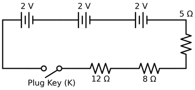
Draw a schematic diagram of a circuit consisting of a battery of three cells of $$2 \, \mathrm{V}$$ each, a $$5 \, \Omega$$ resistor, an $$8 \, \Omega$$ resistor, and a $$12 \, \Omega$$ resistor, and a plug key, all connected in series.
Figure
Figure

Solution

The problem demands only a schematic, nevertheless the steps below make every idea explicit.

Concept of series connection
In a series circuit every component is connected end-to-end, so the same current flows through each of them. Therefore the battery, the plug key and the three resistors must all lie in one continuous loop.

Step-by-step construction of the diagram

  1. Draw the symbol of a battery of three cells: three long–short line pairs in succession. Write “3 × 2 V” (total emf $$6 \text{ V}$$) near it, marking the long lines as the positive terminals.
  2. From the positive terminal run a straight line to a plug key symbol (switch). You may show it open or closed; for a working circuit close it with a small connecting line.
  3. Join the key to a rectangular resistor symbol and label it $$5 \, \Omega$$.
  4. From its far end draw another resistor symbol in the same line, label it $$8 \, \Omega$$.
  5. Connect a third resistor symbol in the line and label it $$12 \, \Omega$$.
  6. Lead the wire from the free end of the $$12 \, \Omega$$ resistor back to the negative terminal of the battery to complete the loop.

Check: All elements lie one after another; no branch exists, so the connection is indeed series. (Optionally note $$E = 3\times2\,\text{V} = 6\,\text{V}$$ and $$R_{\text{eq}} = 5+8+12 = 25\,\Omega$$ beside the diagram.)

Verbal picture of the finished diagram: start with the three-cell battery at the left, then the key, followed by the 5 Ω, 8 Ω, and 12 Ω resistors drawn as three consecutive rectangles, finally returning to the battery, forming a single closed rectangular loop.

Answer

Draw the three cells (3 × 2 V), then the plug key, then the 5 Ω, 8 Ω and 12 Ω resistors one after another in a single closed loop; all components are thus in series.

2 Redraw the circuit of Question 1, putting in an ammeter to measure the current through the resistors and a voltmeter to measure the potential difference across the $$12 \, \Omega$$ resistor. What would be the readings in the ammeter and the voltmeter?

Solution

Step 1 – Redraw and insert the meters

  • Keep the battery, the $$3\,\Omega$$ resistor and the $$12\,\Omega$$ resistor in the same (series) order as in Question 1.
  • Break the connecting wire anywhere in the series path and insert an ammeter; because it must carry the whole circuit current, it is always placed in series.
  • Join the two terminals of a voltmeter directly across the $$12\,\Omega$$ resistor; a voltmeter is connected in parallel with the element across which the potential difference is required.

(Draw a neat circuit diagram showing: battery → ammeter → $$3\,\Omega$$ → $$12\,\Omega$$, with the voltmeter leads touching the two free ends of the $$12\,\Omega$$ resistor.)

Step 2 – Find the total resistance

Because the two resistors are in series, their resistances add directly:

$$R_{\text{eq}} = 3\,\Omega + 12\,\Omega = 15\,\Omega$$

Step 3 – Calculate the circuit current

The battery in Question 1 is rated at $$10\,\text{V}$$. Using Ohm’s law,

$$I = \frac{V}{R_{\text{eq}}} = \frac{10\,\text{V}}{15\,\Omega} = 0.666\ldots\,\text{A} \;\approx\; 0.67\,\text{A}$$

This is the current through every component; hence it is exactly what the ammeter will show.

Step 4 – Potential difference across the $$12\,\Omega$$ resistor

Again by Ohm’s law,

$$V_{12} = I \times 12\,\Omega = 0.666\ldots\,\text{A} \times 12\,\Omega = 8.0\,\text{V}$$

That is the reading of the voltmeter.

Step 5 – Final readings

  • Ammeter: $$0.67\,\text{A}$$ (to two significant figures)
  • Voltmeter: $$8.0\,\text{V}$$

Answer

Ammeter reading ≈ 0.67 A;
Voltmeter reading ≈ 8 V

Intext Questions (Page 188)

1 Judge the equivalent resistance when the following are connected in parallel – (a) $$1 \, \Omega$$ and $$10^6 \, \Omega$$, (b) $$1 \, \Omega$$ and $$10^3 \, \Omega$$, and $$10^6 \, \Omega$$.

Solution

Formula for resistors in parallel
For any number of resistors connected in parallel, the reciprocal of the equivalent resistance $$R_{\mathrm{P}}$$ is the sum of the reciprocals of the individual resistances: $$\dfrac{1}{R_{\mathrm{P}}}=\dfrac{1}{R_1}+\dfrac{1}{R_2}+\dfrac{1}{R_3}+\dots$$

The equivalent resistance is always smaller than the smallest individual resistance in the parallel group.

(a) Two resistors: $$1\,\Omega$$ and $$10^{6}\,\Omega$$

\[\frac{1}{R_{\mathrm{P}}}=\frac{1}{1\,\Omega}+\frac{1}{10^{6}\,\Omega}=1+10^{-6}=1.000001\]

\[R_{\mathrm{P}}=\frac{1}{1.000001}\,\Omega\approx0.999999\,\Omega\]

The value differs from $$1\,\Omega$$ only in the 6th decimal place, so it is practically $$1\,\Omega$$.

(b) Three resistors: $$1\,\Omega$$, $$10^{3}\,\Omega$$ and $$10^{6}\,\Omega$$

\[\frac{1}{R_{\mathrm{P}}}=\frac{1}{1\,\Omega}+\frac{1}{10^{3}\,\Omega}+\frac{1}{10^{6}\,\Omega}=1+0.001+0.000001=1.001001\]

\[R_{\mathrm{P}}=\frac{1}{1.001001}\,\Omega\approx0.9990\,\Omega\]

Again, the result is almost the same as $$1\,\Omega$$. The smallest resistance (here $$1\,\Omega$$) dominates, while very large resistances make a negligible contribution to the equivalent value.

Answer

(a) $$R_{\mathrm{P}}\approx1\,\Omega$$
(b) $$R_{\mathrm{P}}\approx1\,\Omega$$

2 An electric lamp of $$100 \, \Omega$$, a toaster of resistance $$50 \, \Omega$$, and a water filter of resistance $$500 \, \Omega$$ are connected in parallel to a $$220 \, \mathrm{V}$$ source. What is the resistance of an electric iron connected to the same source that takes as much current as all three appliances, and what is the current through it?

Solution

Given: electric lamp resistance $$R_L = 100 \\Omega$$, toaster resistance $$R_T = 50 \\Omega$$ and water filter resistance $$R_W = 500 \\Omega$$, all connected in parallel across a $$V = 220 \\text{ V}$$ supply.

Because they are in parallel, each appliance receives the full 220 V. Using Ohm’s law $$I = \\dfrac{V}{R}$$, the current through each appliance is:

Lamp: $$I_L = \\dfrac{220}{100} = 2.2 \\text{ A}$$

Toaster: $$I_T = \\dfrac{220}{50} = 4.4 \\text{ A}$$

Water filter: $$I_W = \\dfrac{220}{500} = 0.44 \\text{ A}$$

Total current drawn by the three appliances:

$$I_{\\text{total}} = I_L + I_T + I_W = 2.2 + 4.4 + 0.44 = 7.04 \\text{ A}$$

An electric iron is connected to the same 220 V supply and must draw this same current $$I_{\\text{total}} = 7.04 \\text{ A}$$.

Let its resistance be $$R_i$$. From Ohm’s law:

$$R_i = \\dfrac{V}{I_{\\text{total}}} = \\dfrac{220}{7.04} \\approx 31.25 \\Omega$$

  • Resistance of the electric iron: $$R_i \\approx 31.25 \\Omega$$
  • Current through the iron: $$I_i = 7.04 \\text{ A}$$

Answer

Resistance of the electric iron $$R \approx 31.25 \\Omega$$; current through it $$I = 7.04 \\text{A}$$

3 What are the advantages of connecting electrical devices in parallel with the battery instead of connecting them in series?

Solution

Let us compare the electrical conditions in the two possible ways of wiring domestic appliances.

Suppose two devices having resistances $$R_1$$ and $$R_2$$ are connected across a battery of emf $$V$$.

1  Series arrangement

The same current $$I$$ must pass through both devices because there is only one conducting path.

Using Ohm’s law, the current is

$$I = \dfrac{V}{R_1 + R_2}$$

The potential difference that each device actually receives becomes

$$V_1 = I R_1 = \dfrac{V R_1}{R_1 + R_2}, \qquad V_2 = I R_2 = \dfrac{V R_2}{R_1 + R_2}.$$

Thus every appliance gets less than the full battery voltage, so its power output $$P = V^2/R$$ is reduced. Moreover, if either device burns out (its circuit opens) the current $$I$$ becomes zero and all devices stop working.

2  Parallel arrangement

Now the terminals of each appliance are connected directly to the battery terminals, so each branch is at the same potential difference:

$$V_1 = V_2 = V.$$

Hence every appliance works at its rated voltage and delivers its rated power.

The equivalent resistance of the parallel combination is

$$\dfrac{1}{R_{\mathrm p}} = \dfrac{1}{R_1} + \dfrac{1}{R_2}\;\;\Longrightarrow\;\; R_{\mathrm p} < R_1,\; R_2.$$

Because the total resistance is smaller, the current drawn from the source is larger, but the current through any one appliance is independent of the others:

$$I_1 = \dfrac{V}{R_1}, \qquad I_2 = \dfrac{V}{R_2}.$$

If one appliance is switched off or gets disconnected, its branch current becomes zero but the rest of the circuit remains complete; the other devices continue to operate normally.

3  Practical advantages of the parallel connection

  1. Same voltage for all appliances: Each device receives the full mains/battery voltage $$V$$ and hence works at its rated power.
  2. Independent operation: Switching one appliance on or off, or a failure in one branch, does not interrupt the current in the remaining branches.
  3. Lower effective resistance: Adding more devices in parallel decreases the net resistance, preventing undue reduction of current and avoiding dimming of lamps, slowing of fans, etc.
  4. Individual control with separate switches and fuses is possible only when the branches are in parallel.

Because of these reasons household circuits and almost all practical electrical installations connect appliances in parallel rather than in series.

Answer

In parallel each appliance gets the full supply voltage, can be operated or switched off independently, and a fault in one branch does not stop current in the others; moreover, the effective resistance is lowered so no appliance is dimmed or slowed. Hence domestic appliances are always connected in parallel, not in series.

4 How can three resistors of resistances $$2 \, \Omega$$, $$3 \, \Omega$$, and $$6 \, \Omega$$ be connected to give a total resistance of (a) $$4 \, \Omega$$, (b) $$1 \, \Omega$$?

Solution

Given: Three resistors of values $$R_1 = 2 \, \Omega$$, $$R_2 = 3 \, \Omega$$ and $$R_3 = 6 \, \Omega$$.

Formulas needed:

  • Series: $$R_{\text{series}} = R_a + R_b + \dots$$
  • Parallel: $$\dfrac{1}{R_{\text{parallel}}} = \dfrac{1}{R_a} + \dfrac{1}{R_b} + \dots$$; for two resistors $$R_{\text{parallel}} = \dfrac{R_a R_b}{R_a + R_b}$$.

We now treat each required value separately.

(a) Required total resistance $$4 \, \Omega$$

  1. Put $$R_2 = 3 \, \Omega$$ and $$R_3 = 6 \, \Omega$$ in parallel:
    $$R_{23} = \dfrac{R_2 R_3}{R_2 + R_3}= \dfrac{3 \times 6}{3 + 6}= \dfrac{18}{9}= 2 \, \Omega$$.
  2. Connect this parallel pair in series with $$R_1 = 2 \, \Omega$$:
    $$R_{\text{eq}} = R_1 + R_{23}= 2 \, \Omega + 2 \, \Omega = 4 \, \Omega$$.

Hence: parallel combination of 3 Ω and 6 Ω, then in series with 2 Ω, gives the required $$4 \, \Omega$$.

(b) Required total resistance $$1 \, \Omega$$

  1. Connect all three resistors in parallel:
    $$\dfrac{1}{R_{\text{eq}}}= \dfrac{1}{R_1}+ \dfrac{1}{R_2}+ \dfrac{1}{R_3}= \dfrac{1}{2}+ \dfrac{1}{3}+ \dfrac{1}{6}$$.
  2. Common denominator 6:
    $$\dfrac{1}{R_{\text{eq}}}= \dfrac{3}{6}+ \dfrac{2}{6}+ \dfrac{1}{6}= \dfrac{6}{6}= 1$$.
  3. Thus $$R_{\text{eq}} = 1 \, \Omega$$.

So, connecting 2 Ω, 3 Ω and 6 Ω all in parallel gives the required $$1 \, \Omega$$.

Suggested diagrams (to be drawn by the student):
• For part (a) show 3 Ω and 6 Ω side-by-side (parallel) with their common branch in series with 2 Ω.
• For part (b) show all three resistors side-by-side, both ends joined together (pure parallel).

Answer

(a) 3 Ω ∥ 6 Ω, then that branch in series with 2 Ω → $$R_{\text{eq}} = 4 \, \Omega$$.
(b) 2 Ω, 3 Ω and 6 Ω all in parallel → $$R_{\text{eq}} = 1 \, \Omega$$.

5 What is (a) the highest, (b) the lowest total resistance that can be secured by combinations of four coils of resistance $$4 \, \Omega$$, $$8 \, \Omega$$, $$12 \, \Omega$$, $$24 \, \Omega$$?

Solution

The four given resistances are
$$R_1 = 4\,\Omega,\; R_2 = 8\,\Omega,\; R_3 = 12\,\Omega,\; R_4 = 24\,\Omega.$$

Any combination of these coils can only lie between two extreme cases:

  • All in series → gives the maximum possible total resistance.
  • All in parallel → gives the minimum possible total resistance.

(a) Highest (series) value

In series the resistances simply add:
$$R_{\text s}=R_1+R_2+R_3+R_4$$
$$R_{\text s}=4+8+12+24=48\,\Omega.$$

(b) Lowest (parallel) value

The reciprocal of the equivalent resistance is the sum of the reciprocals:
$$\frac{1}{R_{\text p}}=\frac{1}{4}+\frac{1}{8}+\frac{1}{12}+\frac{1}{24}.$$

Take 24 as the lowest common denominator:
$$\frac{1}{R_{\text p}}=\frac{6+3+2+1}{24}=\frac{12}{24}=\frac12.$$

Therefore
$$R_{\text p}=\frac{1}{\tfrac12}=2\,\Omega.$$

Every mixed series–parallel arrangement will have a value between $$2\,\Omega$$ and $$48\,\Omega$$, so these two are the required extreme values.

Answer

(a) Highest possible resistance = $$48\,\Omega$$
(b) Lowest possible resistance = $$2\,\Omega$$

Intext Questions (Page 190)

1 Why does the cord of an electric heater not glow while the heating element does?

Solution

In an electric heater the same current circulates through two quite different conductors:

  • the supply cord (usually made of thick copper), and
  • the heating element (a thin nichrome wire that is wound into a coil).

The brightness (red–orange glow) appears only when the temperature of the conductor rises to about $$800\,\text{°C}$$ or more. Whether a conductor reaches such a temperature is decided by the rate at which it produces heat, given by Joule’s law:

$$H = I^{2} R t \quad\Longrightarrow\quad P = \dfrac{H}{t} = I^{2} R$$

Here $$I$$ is the current through the conductor, $$R$$ its resistance and $$P$$ the thermal power produced.

  1. Resistance of each part
    The nichrome element is long, thin and made of a material whose resistivity is several times that of copper, so its resistance $$R_{\text{element}}$$ is large.
    The copper cord is short, thick and has very low resistivity, so its resistance $$R_{\text{cord}}$$ is tiny (usually a few milliohms).
  2. Heat produced in each part
    Because the same current $$I$$ flows through both, the ratio of heat (or power) evolved is $$\dfrac{P_{\text{element}}}{P_{\text{cord}}}=\dfrac{I^{2} R_{\text{element}}}{I^{2} R_{\text{cord}}}=\dfrac{R_{\text{element}}}{R_{\text{cord}}}\gg 1.$$ Hence the element receives hundreds of times more power than the cord.
  3. Resulting temperature
    The element quickly attains a very high temperature, becomes red–hot and therefore glows.
    The cord develops only a small amount of heat, which is further dissipated over its large cross-sectional area; its temperature rises hardly at all and remains far below the glowing point.

Thus the heating element glows, whereas the supply cord does not.

Answer

The heating element has a very high resistance, so with the same current it produces large heat $$\left(P = I^{2}R\right)$$, becomes red-hot and glows. The cord is thick, copper and of very low resistance; it develops negligible heat and therefore does not glow.

2 Compute the heat generated while transferring $$96000$$ coulomb of charge in one hour through a potential difference of $$50 \, \mathrm{V}$$.

Solution

Given data

  • Charge transferred: $$Q = 96000\,\text{C}$$
  • Potential difference: $$V = 50\,\text{V}$$
  • Time of transfer: $$t = 1\,\text{hour} = 1 \times 60 \times 60\,\text{s} = 3600\,\text{s}$$

Step 1 : Find the current

The electric current is the rate of flow of charge.

$$I = \dfrac{Q}{t} = \dfrac{96000\,\text{C}}{3600\,\text{s}} = 26.67\,\text{A}$$

Step 2 : Relate electrical work and heat produced

When the entire electrical work appears as heat in a conductor, Joule’s law gives

$$H = V I t$$

Substituting the known values:

$$H = (50\,\text{V}) (26.67\,\text{A}) (3600\,\text{s})$$

Calculate the product step by step:

  • First, $$50 \times 26.67 = 1333.5$$
  • Then, $$1333.5 \times 3600 = 4\,800\,600$$

Rounding to three significant figures (the data are given to two significant figures),

$$H \approx 4.80 \times 10^{6}\,\text{J}$$

Alternative direct method

Electrical work done is also $$W = V Q$$, and in this situation $$H = W$$.

$$H = V Q = (50\,\text{V})(96000\,\text{C}) = 4\,800\,000\,\text{J} \;\;(= 4.80 \times 10^{6}\,\text{J})$$

Heat generated:

The conductor releases $$4.8 \times 10^{6}\,\text{joule}$$ of heat.

Answer

$$H = 4.8 \times 10^{6}\,\text{J}$$

3 An electric iron of resistance $$20 \, \Omega$$ takes a current of $$5 \, \mathrm{A}$$. Calculate the heat developed in $$30 \, \mathrm{s}$$.

Solution

Step 1 : Note the given data

  • Resistance of the electric iron: $$R = 20 \, \Omega$$
  • Current taken by the iron: $$I = 5 \, \mathrm{A}$$
  • Time for which the current flows: $$t = 30 \, \mathrm{s}$$

Step 2 : Recall Joule's law of heating

The heat $$H$$ produced when a current $$I$$ passes through a conductor of resistance $$R$$ for time $$t$$ is given by

$$H = I^2 R t$$

Step 3 : Substitute the values

First square the current:

$$I^2 = (5 \, \mathrm{A})^2 = 25 \, \mathrm{A^2}$$

Now put the values into the formula:

$$\begin{aligned}H & = I^2 R t \\[4pt] & = 25 \, \mathrm{A^2} \times 20 \, \Omega \times 30 \, \mathrm{s}\end{aligned}$$

Step 4 : Carry out the multiplication

$$25 \times 20 = 500$$

$$500 \times 30 = 15000$$

Therefore,

$$H = 15000 \, \mathrm{J}$$

Step 5 : Express the heat in a convenient unit

$$15000 \, \mathrm{J} = 1.5 \times 10^4 \, \mathrm{J} = 15 \, \mathrm{kJ}$$

Conclusion

The heat developed in the electric iron in 30 s is $$1.5 \times 10^4 \, \mathrm{J}$$ (or 15 kJ).

Answer

$$H = 1.5 \times 10^4\, \mathrm{J} = 15\, \mathrm{kJ}$$

Intext Questions (Page 192)

1 What determines the rate at which energy is delivered by a current?

Solution

Step 1 – Recall the definition of electric power
Electric power $$P$$ is defined as the rate at which electrical energy is transferred or delivered in a circuit. Mathematically, if an amount of electrical work (or energy) $$W$$ is done in time $$t$$, then

$$P = \dfrac{W}{t}$$

Step 2 – Express the electrical work done in terms of circuit quantities
When a charge $$Q$$ moves through a potential difference $$V$$, the electrical work done is

$$W = V\,Q$$

But the charge that flows in time $$t$$ when a steady current $$I$$ exists is

$$Q = I\,t$$

Step 3 – Substitute for $$W$$ and $$Q$$ in the power formula

$$P = \dfrac{W}{t} = \dfrac{V\,Q}{t} = \dfrac{V\,(I\,t)}{t} = V I$$

Step 4 – Alternative forms using Ohm’s law
Using Ohm’s law, $$V = I R$$, we can write

$$P = V I = (I R) I = I^2 R$$

or, eliminating $$I$$ instead, $$I = \dfrac{V}{R}$$ gives
$$P = V I = V \left(\dfrac{V}{R}\right) = \dfrac{V^2}{R}$$

Conclusion
The rate at which energy is delivered (i.e. the power) depends on the magnitude of the current through the circuit and the potential difference across it (or, equivalently, on $$I$$ and $$R$$, or on $$V$$ and $$R$$).

Answer

The rate at which energy is delivered by a current is determined by both the current $$I$$ and the potential difference $$V$$ (since $$P = VI = I^2R = \dfrac{V^2}{R}$$).

2 An electric motor takes $$5 \, \mathrm{A}$$ from a $$220 \, \mathrm{V}$$ line. Determine the power of the motor and the energy consumed in $$2 \, \mathrm{h}$$.

Solution

Given data

  • Potential difference (supply voltage): $$V = 220\,\text{V}$$
  • Current drawn by the motor: $$I = 5\,\text{A}$$
  • Time of operation: $$t = 2\,\text{h}$$

We have to calculate

  1. the power $$P$$ of the motor, and
  2. the electrical energy $$E$$ consumed in the given time.

1. Calculating the power of the motor

For any electrical appliance operated at a potential difference $$V$$ and drawing current $$I$$, the power $$P$$ is

$$P = V I$$

Substituting the given values:

$$P = 220\,\text{V}\;\times\;5\,\text{A}$$

$$P = 1100\,\text{W}$$

Since $$1000\,\text{W} = 1\,\text{kW}$$, we can also write

$$P = \frac{1100}{1000}\,\text{kW} = 1.1\,\text{kW}$$

2. Calculating the energy consumed in 2 h

Electrical energy consumed is given by

$$E = P t$$

(i) Energy in kilowatt–hour (kWh)

Using power in kilowatts and time in hours:

$$E = 1.1\,\text{kW} \times 2\,\text{h}$$

$$E = 2.2\,\text{kWh}$$

(ii) Energy in joules

We know $$1\,\text{kWh} = 3.6 \times 10^6\,\text{J}$$.

Therefore

$$E = 2.2\,\text{kWh} \times 3.6 \times 10^6\,\text{J kWh}^{-1}$$

$$E = 7.92 \times 10^6\,\text{J}$$

Final results

  • Power of the motor: $$P = 1100\,\text{W} = 1.1\,\text{kW}$$
  • Energy consumed in $$2\,\text{h}:$$ $$E = 2.2\,\text{kWh} = 7.92\times10^6\,\text{J}$$

Answer

The motor’s power is $$1.1\,\text{kW}$$ and the energy consumed in $$2\,\text{h}$$ is $$2.2\,\text{kWh}\;(7.92\times10^6\,\text{J}).$$

Exercises

1

A piece of wire of resistance $$R$$ is cut into five equal parts. These parts are then connected in parallel. If the equivalent resistance of this combination is $$R'$$, then the ratio $$R/R'$$ is –

(a) $$1/25$$    (b) $$1/5$$    (c) $$5$$    (d) $$25$$

Solution

Let the resistance of the original wire be $$R$$.

1. Resistance of each piece
The wire is cut into five equal lengths. Because resistance is directly proportional to length, the resistance of every small piece is

$$R_{\text{piece}} = \frac{R}{5}$$

2. Equivalent resistance in parallel
Five such resistors are now connected in parallel. For resistors in parallel,

$$\frac{1}{R'} = \sum \frac{1}{R_{\text{piece}}}$$

Since all five resistors have the same value $$R_{\text{piece}}$$,

$$\frac{1}{R'} = 5 \times \frac{1}{R_{\text{piece}}} = 5 \times \frac{1}{R/5} = \frac{25}{R}$$

$$\Rightarrow \; R' = \frac{R}{25}$$

3. Required ratio

$$\frac{R}{R'} = \frac{R}{R/25} = 25$$

Hence, $$\dfrac{R}{R'} = 25$$. The correct option is (d).

Answer

(d) 25

2

Which of the following terms does not represent electrical power in a circuit?

(a) $$I^2 R$$    (b) $$I R^2$$    (c) $$VI$$    (d) $$V^2/R$$

Solution

Given options

  1. $$(a)\;I^2 R$$
  2. $$(b)\;I R^2$$
  3. $$(c)\;VI$$
  4. $$(d)\;V^2/R$$

Step 1 — Recall the definition of electric power

Electric power $$P$$ is the rate at which electrical energy is consumed or supplied in a circuit. If a potential difference $$V$$ is applied across a component and an electric current $$I$$ flows through it, then

$$P = VI$$


Step 2 — Generate equivalent formulas using Ohm’s law

Ohm’s law gives the relation $$V = IR$$, where $$R$$ is the resistance of the component.

  • Substitute $$V = IR$$ in $$P = VI$$:
    $$P = I( IR ) = I^2 R$$
  • Alternatively, write $$I = V/R$$ and substitute in $$P = VI$$:
    $$P = V\left( \dfrac{V}{R} \right) = \dfrac{V^2}{R}$$

Thus the three correct, equivalent expressions for electrical power are

  • $$P = VI$$
  • $$P = I^2 R$$
  • $$P = V^2/R$$

Step 3 — Identify the incorrect option

The expression $$I R^2$$ cannot be obtained from the power formula using Ohm’s law and has incorrect dimensions for power. Therefore it does not represent electrical power.

Answer

(b) $$I R^2$$

3

An electric bulb is rated $$220 \, \mathrm{V}$$ and $$100 \, \mathrm{W}$$. When it is operated on $$110 \, \mathrm{V}$$, the power consumed will be –

(a) $$100 \, \mathrm{W}$$    (b) $$75 \, \mathrm{W}$$    (c) $$50 \, \mathrm{W}$$    (d) $$25 \, \mathrm{W}$$

Solution

The rating $$220 \, \mathrm{V},\;100 \, \mathrm{W}$$ means the bulb draws $$100 \, \mathrm{W}$$ of power when the applied potential difference is $$220 \, \mathrm{V}$$.

Step 1 – Find the resistance of the filament

For any resistor, $$P = V^2/R$$. Rearranging,

$$R = \frac{V^2}{P} = \frac{(220 \, \mathrm{V})^2}{100 \, \mathrm{W}} = \frac{48400}{100} \, \Omega = 484 \, \Omega.$$

Step 2 – Power at the new voltage

The resistance of the filament is taken to be nearly constant, so for an applied voltage $$V' = 110 \, \mathrm{V}$$ the power $$P'$$ is

$$P' = \frac{V'^2}{R} = \frac{(110 \, \mathrm{V})^2}{484 \, \Omega} = \frac{12100}{484} \, \mathrm{W}.$$

Carrying out the division,

$$\frac{12100}{484} = 25 \, \mathrm{W}.$$

Result   The bulb will consume $$25 \, \mathrm{W}$$ when connected to a $$110 \, \mathrm{V}$$ supply.

Hence, the correct option is (d).

Answer

(d) $$25 \, \mathrm{W}$$

4

Two conducting wires of the same material and of equal lengths and equal diameters are first connected in series and then parallel in a circuit across the same potential difference. The ratio of heat produced in series and parallel combinations would be –

(a) $$1:2$$    (b) $$2:1$$    (c) $$1:4$$    (d) $$4:1$$

Solution

Let each wire have resistance $$R$$. (They are identical because material, length and diameter are the same.)

1. Series combination

Equivalent resistance: $$R_{\mathrm{s}} = R + R = 2R$$.

For a constant potential difference $$V$$ applied for time $$t$$, the heat produced is given by Joule’s law, $$H = \dfrac{V^2 t}{R_{\mathrm{eq}}}$$.

Hence for series,

$$H_{\mathrm{s}} = \dfrac{V^2 t}{2R}$$.

2. Parallel combination

Equivalent resistance: $$R_{\mathrm{p}} = \dfrac{R\,R}{R+R} = \dfrac{R}{2}$$.

Heat produced in the same time $$t$$ is

$$H_{\mathrm{p}} = \dfrac{V^2 t}{R_{\mathrm{p}}} = \dfrac{V^2 t}{\tfrac{R}{2}} = \dfrac{2V^2 t}{R}$$.

3. Ratio of heats

$$\dfrac{H_{\mathrm{s}}}{H_{\mathrm{p}}} = \dfrac{ \tfrac{V^2 t}{2R} }{ \tfrac{2V^2 t}{R} } = \dfrac{1}{2} : 2 = 1 : 4$$.

Therefore, the heat produced in series and parallel combinations are in the ratio $$1:4$$.

Correct option: (c).

Answer

(c)  $$1:4$$

5 How is a voltmeter connected in the circuit to measure the potential difference between two points?

Solution

Concept recalled

A voltmeter is meant to measure potential difference, i.e. the work done per unit charge in moving a small test charge from one point to another in a circuit. If the two points are labelled $$A$$ and $$B$$, the potential difference is $$V_{AB} = V_A - V_B$$.

Essential property of a voltmeter

  • A practical voltmeter is designed with a very high resistance (ideally infinite) so that it draws negligible current from the circuit branch whose voltage is to be measured.

Correct way to join the instrument

  1. Take the two terminals of the voltmeter.
  2. Connect one terminal directly to point $$A$$ and the other terminal directly to point $$B$$.
  3. This places the voltmeter in parallel with the circuit element (or section of wire) between $$A$$ and $$B$$, so the instrument experiences exactly the same potential difference as that section.

Why not in series?

  • If a voltmeter were inserted in series, its large resistance would drastically reduce the circuit current according to Ohm’s law $$I = \dfrac{V}{R_{\text{total}}}$$, disturbing the original operating conditions and giving a meaningless reading.

Conclusion

Therefore, to measure the potential difference between two points of a circuit, the voltmeter must always be connected across (in parallel with) those two points.


Answer

The voltmeter is connected in parallel across the two given points so that it reads the exact potential difference between them without altering the circuit current.

6 A copper wire has diameter $$0.5 \, \mathrm{mm}$$ and resistivity of $$1.6 \times 10^{-8} \, \Omega \, \mathrm{m}$$. What will be the length of this wire to make its resistance $$10 \, \Omega$$? How much does the resistance change if the diameter is doubled?

Solution

Given data

  • Diameter of the copper wire: $$d = 0.5\,\text{mm} = 0.5 \times 10^{-3}\,\text{m}$$
  • Resistivity of copper: $$\rho = 1.6 \times 10^{-8}\,\Omega\,\text{m}$$
  • Required resistance: $$R = 10\,\Omega$$

1. Cross-sectional area of the wire

The radius is half the diameter:

$$r = \frac{d}{2} = \frac{0.5 \times 10^{-3}\,\text{m}}{2} = 0.25 \times 10^{-3}\,\text{m} = 2.5 \times 10^{-4}\,\text{m}$$

Area of a circle is $$A = \pi r^2$$, therefore

$$\begin{aligned} A &= \pi (2.5 \times 10^{-4}\,\text{m})^2\\ &= \pi (6.25 \times 10^{-8})\,\text{m}^2\\ &= 6.25\pi \times 10^{-8}\,\text{m}^2\\ &\approx 1.96 \times 10^{-7}\,\text{m}^2. \end{aligned}$$

2. Length for a resistance of 10 Ω

The resistance of a uniform wire is

$$R = \rho \frac{\ell}{A} \;\;\Rightarrow\;\; \ell = \frac{R A}{\rho}$$

Substituting the known quantities,

$$\begin{aligned} \ell &= \frac{10\,\Omega \;(1.96 \times 10^{-7}\,\text{m}^2)}{1.6 \times 10^{-8}\,\Omega\,\text{m}}\\[4pt] &= \frac{1.962 \times 10^{-6}\,\Omega\,\text{m}}{1.6 \times 10^{-8}\,\Omega\,\text{m}}\\[4pt] &= 1.23 \times 10^{2}\,\text{m}\\ &\approx 123\,\text{m}. \end{aligned}$$

3. Effect of doubling the diameter

New diameter: $$d' = 2d \;\;\Longrightarrow\;\; r' = 2r$$

Because area depends on the square of the radius,

$$A' = \pi r'^2 = \pi (2r)^2 = 4\pi r^2 = 4A$$

Keeping length and resistivity unchanged, the new resistance is

$$R' = \rho \frac{\ell}{A'} = \rho \frac{\ell}{4A} = \frac{R}{4}$$

Therefore,

$$R' = \frac{10\,\Omega}{4} = 2.5\,\Omega$$

Result

  • Length of the wire required for 10 Ω: about 123 m.
  • If the diameter is doubled, the resistance becomes 2.5 Ω (one-quarter of the original value).

Answer

Length ≈ $$123\,\text{m}$$;
on doubling the diameter the resistance becomes $$2.5\,\Omega$$.

7

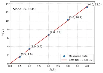
The values of current $$I$$ flowing in a given resistor for the corresponding values of potential difference $$V$$ across the resistor are given below –

$$I$$ (amperes)$$V$$ (volts)
$$0.5$$$$1.6$$
$$1.0$$$$3.4$$
$$2.0$$$$6.7$$
$$3.0$$$$10.2$$
$$4.0$$$$13.2$$

Plot a graph between $$V$$ and $$I$$ and calculate the resistance of that resistor.

Figure
Figure

Solution

Step 1  – Rewrite the observations

Current $$I$$ (A)Potential difference $$V$$ (V)
$$0.5$$$$1.6$$
$$1.0$$$$3.4$$
$$2.0$$$$6.7$$
$$3.0$$$$10.2$$
$$4.0$$$$13.2$$

Step 2  – Plot the graph of $$V$$ (vertical axis) versus $$I$$ (horizontal axis)

  • Choose a convenient scale, e.g. along the $$I$$-axis: $$1\text{ cm}=0.5\,\text{A}$$; along the $$V$$-axis: $$1\text{ cm}=2\,\text{V}$$.
  • Mark and plot the five points: $$(0.5,1.6),\,(1.0,3.4),\,(2.0,6.7),\,(3.0,10.2),\,(4.0,13.2)$$.
  • All the points nearly fall on a straight line. Draw the best-fit straight line; it should pass through the origin if extended (Ohm’s law).

[The student should draw the axes, mark the scale, plot the points and draw the straight line as described.]

Step 3  – Find the slope of the $$V$$–$$I$$ line

Choose two widely separated points on the straight line (use exact plotted values, not necessarily the experimental points). For numerical work we may take the extreme measured points:

$$I_1 = 0.5\,\text{A}, \; V_1 = 1.6\,\text{V}$$
$$I_2 = 4.0\,\text{A}, \; V_2 = 13.2\,\text{V}$$

Calculate the slope:

$$\text{slope} = \frac{\Delta V}{\Delta I} = \frac{V_2 - V_1}{I_2 - I_1} = \frac{13.2 - 1.6}{4.0 - 0.5} = \frac{11.6}{3.5} \;\text{V A}^{-1} \approx 3.3\,\Omega$$

Step 4  – Resistance of the resistor

The slope of the $$V$$–$$I$$ graph equals the resistance $$R$$, therefore

$$R \approx 3.3\,\Omega$$

Taking the average of $$V/I$$ for all the given observations also gives roughly the same value (between $$3.2\,\Omega$$ and $$3.4\,\Omega$$), confirming the result.

Answer

Resistance of the resistor  $$R \approx 3.3\,\Omega$$

8 When a $$12 \, \mathrm{V}$$ battery is connected across an unknown resistor, there is a current of $$2.5 \, \mathrm{mA}$$ in the circuit. Find the value of the resistance of the resistor.

Solution

The resistance can be calculated from Ohm’s law.

Step 1 — Write the given data.
Potential difference: $$V = 12\,\mathrm{V}$$
Current: $$I = 2.5\,\mathrm{mA}$$

Step 2 — Convert the current to ampere.
Since $$1\,\mathrm{mA} = 1 \times 10^{-3}\,\mathrm{A}$$, $$I = 2.5 \times 10^{-3}\,\mathrm{A}$$

Step 3 — Apply Ohm’s law.
Ohm’s law gives $$R = \dfrac{V}{I}$$

Substituting the values:
$$R = \dfrac{12\,\mathrm{V}}{2.5 \times 10^{-3}\,\mathrm{A}}$$

Step 4 — Do the arithmetic.
First divide the numbers: $$\dfrac{12}{2.5} = 4.8$$
Then handle the powers of ten: $$\dfrac{1}{10^{-3}} = 10^{3}$$
Therefore $$R = 4.8 \times 10^{3}\,\mathrm{\Omega}$$

Step 5 — Write the final resistance.
$$R = 4800\,\mathrm{\Omega} = 4.8\,\mathrm{k\Omega}$$

Answer

$$R = 4.8\,\mathrm{k\Omega}$$

9 A battery of $$9 \, \mathrm{V}$$ is connected in series with resistors of $$0.2 \, \Omega$$, $$0.3 \, \Omega$$, $$0.4 \, \Omega$$, $$0.5 \, \Omega$$ and $$12 \, \Omega$$, respectively. How much current would flow through the $$12 \, \Omega$$ resistor?

Solution

Given data

  • Battery (source) potential difference: $$V = 9\,\text{V}$$
  • Series resistors: $$R_1 = 0.2\,\Omega$$, $$R_2 = 0.3\,\Omega$$, $$R_3 = 0.4\,\Omega$$, $$R_4 = 0.5\,\Omega$$ and $$R_5 = 12\,\Omega$$

Step 1. Find the equivalent resistance of the series combination

For resistors joined in series, the total (equivalent) resistance is the algebraic sum of the individual resistances:

$$R_{\text{eq}} = R_1 + R_2 + R_3 + R_4 + R_5$$

Substituting the given values,

$$R_{\text{eq}} = 0.2\,\Omega + 0.3\,\Omega + 0.4\,\Omega + 0.5\,\Omega + 12\,\Omega$$

$$R_{\text{eq}} = (0.2 + 0.3 + 0.4 + 0.5)\,\Omega + 12\,\Omega$$

$$R_{\text{eq}} = 1.4\,\Omega + 12\,\Omega$$

$$R_{\text{eq}} = 13.4\,\Omega$$

Step 2. Apply Ohm’s law to find the circuit current

In a series circuit the same current $$I$$ flows through every resistor. Ohm’s law gives

$$I = \frac{V}{R_{\text{eq}}}$$

Substitute $$V = 9\,\text{V}$$ and $$R_{\text{eq}} = 13.4\,\Omega$$:

$$I = \frac{9\,\text{V}}{13.4\,\Omega}$$

To two decimal places,

$$I \approx 0.67\,\text{A}$$

Step 3. State the required current

Because all the resistors are in series, the current through the $$12\,\Omega$$ resistor is the same as the circuit current just calculated.

Therefore, the current flowing through the $$12\,\Omega$$ resistor is $$0.67\,\text{A} \,(\text{approximately})$$.

Answer

Current through the $$12\,\Omega$$ resistor  =  $$0.67\,\text{A}$$ (approx.)

10 How many $$176 \, \Omega$$ resistors (in parallel) are required to carry $$5 \, \mathrm{A}$$ on a $$220 \, \mathrm{V}$$ line?

Solution

Given data

  • Resistance of each resistor: $$R = 176\,\Omega$$
  • Supply voltage: $$V = 220\,\mathrm{V}$$
  • Total current required: $$I = 5\,\mathrm{A}$$

1. Find the equivalent resistance needed

Ohm’s law gives $$V = IR$$ for the entire parallel combination. Hence

$$R_{\text{eq}} = \frac{V}{I} = \frac{220\,\mathrm{V}}{5\,\mathrm{A}} = 44\,\Omega$$

2. Relate the equivalent resistance to the number of resistors

For n identical resistors each of resistance $$R$$ connected in parallel,

$$\frac{1}{R_{\text{eq}}} = \frac{1}{R} + \frac{1}{R} + \cdots + \frac{1}{R}\;(n\;\text{times}) = \frac{n}{R}$$

Therefore $$R_{\text{eq}} = \frac{R}{n}$$.

Substitute $$R = 176\,\Omega$$ and $$R_{\text{eq}} = 44\,\Omega$$:

$$44\,\Omega = \frac{176\,\Omega}{n}$$

$$n = \frac{176}{44} = 4$$

3. Result

Exactly 4 resistors of $$176\,\Omega$$ each, connected in parallel, are required.

Answer

4 resistors

11 Show how you would connect three resistors, each of resistance $$6 \, \Omega$$, so that the combination has a resistance of (i) $$9 \, \Omega$$, (ii) $$4 \, \Omega$$.

Solution

Let the three given resistors be labelled $$R_1 , R_2 , R_3$$. For each problem we decide first whether we need a series or a parallel portion, then compute the equivalent resistance of that portion and finally combine it with the remaining resistor.

Given  $$R_1 = R_2 = R_3 = 6\,\Omega$$

(i) Required equivalent resistance  $$R_{eq}=9\,\Omega$$

  1. Put two resistors in parallel.
    The parallel branch is chosen because a parallel combination always gives a value smaller than the individual resistances; afterwards that smaller value can be increased by adding the third resistor in series. $$\frac{1}{R_P}=\frac{1}{R_1}+\frac{1}{R_2}=\frac{1}{6}+\frac{1}{6}=\frac{2}{6}$$ $$R_P=\frac{6}{2}=3\,\Omega$$
  2. Place the third resistor in series with the parallel branch.
    $$R_{eq}=R_P+R_3=3+6=9\,\Omega$$
  3. How to wire it.
    • Join one end of $$R_1$$ to one end of $$R_2$$, and join their other ends together as well; that gives the 3-Ω parallel block.
    • Connect one of the common ends of this block to one end of $$R_3$$; the free end of $$R_3$$ becomes the other terminal of the combination.
    Thus current first splits equally through $$R_1$$ and $$R_2$$ (parallel) and then passes through $$R_3$$ (series).

(ii) Required equivalent resistance  $$R_{eq}=4\,\Omega$$

  1. Put two resistors in series.
    $$R_S = R_1 + R_2 = 6 + 6 = 12\,\Omega$$
  2. Place this series pair in parallel with the third resistor.
    $$\frac{1}{R_{eq}} = \frac{1}{R_S} + \frac{1}{R_3} = \frac{1}{12} + \frac{1}{6} = \frac{1}{12} + \frac{2}{12} = \frac{3}{12}$$ $$R_{eq} = \frac{12}{3} = 4\,\Omega$$
  3. How to wire it.
    • First join $$R_1$$ and $$R_2$$ end-to-end so that the same current must flow through both (series).
    • Now connect the free end of $$R_1$$ and the free end of $$R_2$$ together with the two ends of $$R_3$$ so that the 12-Ω pair and the single 6-Ω resistor share the same two terminals (parallel).
    In the finished circuit current can choose either the single 6-Ω path or the 12-Ω two-resistor path, giving the required 4-Ω resultant.

Therefore both target resistances can be obtained with simple series–parallel combinations of the three 6-Ω resistors.

Answer

(i) Two resistors in parallel, the third in series ⇒ $$R_{eq}=9\,\Omega$$
(ii) Two resistors in series, that pair in parallel with the third ⇒ $$R_{eq}=4\,\Omega$$

12 Several electric bulbs designed to be used on a $$220 \, \mathrm{V}$$ electric supply line, are rated $$10 \, \mathrm{W}$$. How many lamps can be connected in parallel with each other across the two wires of $$220 \, \mathrm{V}$$ line if the maximum allowable current is $$5 \, \mathrm{A}$$?

Solution

Data provided
Rated power of each lamp: $$P = 10 \\mathrm{W}$$
Rated supply voltage: $$V = 220 \\mathrm{V}$$
Maximum current that may be taken from the line: $$I_{\max} = 5 \\mathrm{A}$$

Step 1 – Current drawn by one lamp
For any appliance, rated power and voltage are related by
$$P = V I\;.$$
Hence the current taken by a single bulb is
$$I_1 = \frac{P}{V} = \frac{10}{220} = 0.04545\;\mathrm{A} \;(\approx 45\;\mathrm{mA}).$$

Step 2 – Number of lamps that can be connected
If $$n$$ identical lamps are connected in parallel, the total current will be
$$I_{\text{total}} = n I_1.$$(The voltage across each lamp stays at $$220\;\mathrm{V}$$ in a parallel circuit.)
The circuit must satisfy
$$I_{\text{total}} \le I_{\max} \;\Rightarrow\; n I_1 \le 5.$$
Substituting $$I_1 = 10/220$$, we get
$$n \le \frac{5}{10/220} = 5 \times \frac{220}{10} = 110.$$

Conclusion
The largest whole number of 10 W, 220 V lamps that can be run in parallel without exceeding the 5 A limit is one hundred and ten.

Answer

$$110$$ lamps

13 A hot plate of an electric oven connected to a $$220 \, \mathrm{V}$$ line has two resistance coils A and B, each of $$24 \, \Omega$$ resistance, which may be used separately, in series, or in parallel. What are the currents in the three cases?

Solution

The supply voltage is common for all the arrangements:

$$V = 220\,\text{V}$$    Each coil: $$R_A = R_B = 24\,\Omega$$

(i) Either coil used separately

  • Equivalent resistance: $$R = 24\,\Omega$$
  • Current: $$I = \dfrac{V}{R} = \dfrac{220\,\text{V}}{24\,\Omega} = \dfrac{55}{6}\,\text{A} \approx 9.17\,\text{A}$$

(ii) Two coils in series

  • Series resistance: $$R_s = R_A + R_B = 24\,\Omega + 24\,\Omega = 48\,\Omega$$
  • Current: $$I_s = \dfrac{V}{R_s} = \dfrac{220\,\text{V}}{48\,\Omega} = \dfrac{55}{12}\,\text{A} \approx 4.58\,\text{A}$$

(iii) Two coils in parallel

  • Parallel resistance:
    $$\frac{1}{R_p} = \frac{1}{24\,\Omega} + \frac{1}{24\,\Omega} = \frac{2}{24}\,\Omega^{-1} = \frac{1}{12}\,\Omega^{-1}$$
    $$\Rightarrow \; R_p = 12\,\Omega$$
  • Current: $$I_p = \dfrac{V}{R_p} = \dfrac{220\,\text{V}}{12\,\Omega} = \dfrac{55}{3}\,\text{A} \approx 18.3\,\text{A}$$

Thus, the current drawn is largest when the coils are in parallel, smallest when they are in series, and intermediate when only one coil is used.

Answer

One coil only: $$I \approx 9.2\,\text{A}$$
Two coils in series: $$I \approx 4.6\,\text{A}$$
Two coils in parallel: $$I \approx 18.3\,\text{A}$$

14 Compare the power used in the $$2 \, \Omega$$ resistor in each of the following circuits: (i) a $$6 \, \mathrm{V}$$ battery in series with $$1 \, \Omega$$ and $$2 \, \Omega$$ resistors, and (ii) a $$4 \, \mathrm{V}$$ battery in parallel with $$12 \, \Omega$$ and $$2 \, \Omega$$ resistors.

Solution

Given data

  • Case (i): $$V = 6 \, \mathrm{V}$$, resistors $$R_1 = 1 \, \Omega$$ and $$R_2 = 2 \, \Omega$$ in series.
  • Case (ii): $$V = 4 \, \mathrm{V}$$, resistors $$R_3 = 12 \, \Omega$$ and the same $$R_2 = 2 \, \Omega$$ in parallel.

Find the power dissipated in the $$2 \, \Omega$$ resistor in each case.

(i) Series circuit

Total resistance: $$R_{\text{series}} = R_1 + R_2 = 1 + 2 = 3 \, \Omega$$

Current: $$I = \dfrac{V}{R_{\text{series}}} = \dfrac{6}{3} = 2 \, \mathrm{A}$$

Voltage across $$2 \, \Omega$$: $$V_{2\Omega} = I R_2 = 2 \times 2 = 4 \, \mathrm{V}$$

Power: $$P_1 = I^2 R_2 = (2)^2 \times 2 = 8 \, \mathrm{W}$$

(ii) Parallel circuit

Voltage across each branch equals the supply: $$V_{2\Omega} = 4 \, \mathrm{V}$$

Current through $$2 \, \Omega$$: $$I = \dfrac{V_{2\Omega}}{R_2} = \dfrac{4}{2} = 2 \, \mathrm{A}$$

Power: $$P_2 = V_{2\Omega} I = 4 \times 2 = 8 \, \mathrm{W}$$ (also $$P_2 = \dfrac{V^2}{R_2} = 8 \, \mathrm{W}$$).

Comparison

$$P_1 = 8 \, \mathrm{W}, \; P_2 = 8 \, \mathrm{W}$$  ⇒  The $$2 \, \Omega$$ resistor uses the same power in both circuits.

Answer

The $$2 \, \Omega$$ resistor dissipates $$8 \, \mathrm{W}$$ in each circuit; the powers are equal.

15 Two lamps, one rated $$100 \, \mathrm{W}$$ at $$220 \, \mathrm{V}$$, and the other $$60 \, \mathrm{W}$$ at $$220 \, \mathrm{V}$$, are connected in parallel to electric mains supply. What current is drawn from the line if the supply voltage is $$220 \, \mathrm{V}$$?

Solution

Given data

  • Lamp A (bulb 1): rating $$P_1 = 100\,\mathrm{W}$$, $$V_1 = 220\,\mathrm{V}$$
  • Lamp B (bulb 2): rating $$P_2 = 60\,\mathrm{W}$$, $$V_2 = 220\,\mathrm{V}$$
  • Connection: parallel across mains of $$V = 220\,\mathrm{V}$$.

Because the lamps are in parallel, each lamp receives the full line voltage of $$220\,\mathrm{V}$$, exactly the voltage for which their power ratings are specified. Therefore each lamp draws its rated power.

Step 1: Current drawn by lamp A

The electric power formula is $$P = V I$$. Solving for current, $$I = \dfrac{P}{V}$$.

For lamp A:

$$I_1 = \dfrac{P_1}{V_1} = \dfrac{100\,\mathrm{W}}{220\,\mathrm{V}} = 0.455\,\mathrm{A}\,(\text{approximately}).$$

Step 2: Current drawn by lamp B

For lamp B:

$$I_2 = \dfrac{P_2}{V_2} = \dfrac{60\,\mathrm{W}}{220\,\mathrm{V}} = 0.273\,\mathrm{A}\,(\text{approximately}).$$

Step 3: Total current from the mains

In a parallel circuit, the line (supply) current is the arithmetic sum of the branch currents:

$$I_{\text{total}} = I_1 + I_2$$

Substituting the calculated values,

$$I_{\text{total}} = 0.455\,\mathrm{A} + 0.273\,\mathrm{A} = 0.728\,\mathrm{A}.$$

Result

The current drawn from the 220 V mains by the two lamps connected in parallel is $$0.73\,\mathrm{A}\;\text{(to two significant figures)}$$.

Answer

$$I_{\text{total}} \approx 0.73\,\mathrm{A}$$

16 Which uses more energy, a $$250 \, \mathrm{W}$$ TV set in 1 hr, or a $$1200 \, \mathrm{W}$$ toaster in 10 minutes?

Solution

Given data

  • Power of the TV set $$P_{1}=250\,\text{W}$$; operating time $$t_{1}=1\,\text{h}$$.
  • Power of the toaster $$P_{2}=1200\,\text{W}$$; operating time $$t_{2}=10\,\text{min}$$.

Energy consumed by an electrical appliance

The energy consumed is the product of power and time:

$$E=P\times t$$

Step 1: Express all times in the same unit

  • TV set: $$t_{1}=1\,\text{h}=60\,\text{min}=3600\,\text{s}$$
  • Toaster: $$t_{2}=10\,\text{min}=\frac{10}{60}\,\text{h}=\frac16\,\text{h}=600\,\text{s}$$

Step 2: Calculate energy in watt-hours

TV set:

$$E_{1}=P_{1}\times t_{1}=250\,\text{W}\times1\,\text{h}=250\,\text{Wh}$$

Toaster:

$$E_{2}=P_{2}\times t_{2}=1200\,\text{W}\times\frac16\,\text{h}=200\,\text{Wh}$$

Step 3: Optional conversion to joule

Since $$1\,\text{Wh}=3600\,\text{J}$$:

  • $$E_{1}=250\,\text{Wh}\times3600\,\text{J/Wh}=9.0\times10^{5}\,\text{J}$$
  • $$E_{2}=200\,\text{Wh}\times3600\,\text{J/Wh}=7.2\times10^{5}\,\text{J}$$

Comparison

$$E_{1}=250\,\text{Wh}>E_{2}=200\,\text{Wh}$$

Conclusion

The 250 W TV set used for 1 hour consumes more energy than the 1200 W toaster used for 10 minutes.

Answer

The 250 W TV set in 1 h (250 Wh) consumes more energy than the 1200 W toaster in 10 min (200 Wh).

17 An electric heater of resistance $$44 \, \Omega$$ draws $$5 \, \mathrm{A}$$ from the service mains for 2 hours. Calculate the rate at which heat is developed in the heater.

Solution

Given data

  • Resistance of heater, $$R = 44\,\Omega$$
  • Current drawn, $$I = 5\,\mathrm{A}$$
  • Time of operation, $$t = 2\,\mathrm{h} = 2 \times 60 \times 60 = 7200\,\mathrm{s}$$ (not needed for the required quantity but noted)

Concept

The rate at which heat is produced in an electrical device is the electric power dissipated in it. For a resistance $$R$$ carrying current $$I$$, the power is

$$P = I^2 R$$

Calculation

Substitute the given values:

$$P = (5\,\mathrm{A})^2 \times 44\,\Omega = 25 \times 44 = 1100\,\mathrm{W}$$

Convert to kilowatts

$$1100\,\mathrm{W} = \frac{1100}{1000}\,\mathrm{kW} = 1.1\,\mathrm{kW}$$

Therefore, the heater develops heat at the rate of $$1.1\,\mathrm{kW}$$ (i.e. $$1100\,\mathrm{J\,s^{-1}}$$).

Answer

Rate of heat development = $$P = 1.1\,\mathrm{kW}$$

18 Explain the following.

(a) Why is the tungsten used almost exclusively for filament of electric lamps?

Solution

For an incandescent lamp the filament has to be raised to about 2500–2800 °C so that it glows white-hot. The material chosen must therefore

  • possess a very high melting point so that it does not fuse at the working temperature,
  • have a fairly high resistivity so that the required temperature is reached with a small length of wire,
  • retain good mechanical strength even when it is red hot so that it can be drawn into very fine spirals.

Tungsten fits these requirements better than any other metal: its melting point is $$3380^{\circ}\text{C}$$ (the highest for common metals), its resistivity $$\bigl(5.6\times10^{-8}\,\Omega\,\text{m}\bigr)$$ is large enough to produce intense heating, and it has excellent tensile strength. Hence tungsten is used almost exclusively for lamp filaments.

Answer

Tungsten is used because it has an extremely high melting point, fairly high resistivity and good mechanical strength; therefore it can be heated to white-hot temperatures without melting and withstanding mechanical stresses.

(b) Why are the conductors of electric heating devices, such as bread-toasters and electric irons, made of an alloy rather than a pure metal?

Solution

Heating appliances employ wires of alloys such as nichrome (Ni–Cr) instead of pure metals because:

  • High resistivity: The resistivity of nichrome is about 60 – 80 times that of copper. For the same current it produces much more heat in a short, conveniently small length of wire.
  • Small temperature coefficient: The resistance of these alloys changes very little with temperature, so the heat output stays almost constant when the element becomes red hot.
  • High melting point & oxidation resistance: Alloys oxidise and burn much less than pure metals at high temperatures; hence the element lasts longer in air.

Because of these advantages conductors of bread-toasters, irons and similar devices are always made of an alloy rather than a pure metal.

Answer

Alloys such as nichrome have much higher resistivity, a very small temperature coefficient and resist oxidation at red-hot temperatures; therefore they produce the necessary heat without burning out, unlike pure metals.

(c) Why is the series arrangement not used for domestic circuits?

Solution

Domestic wiring is never done in series for the following reasons:

  1. Same current through all appliances: In a series circuit the current is the same everywhere. Different appliances generally require different currents for proper working; this condition cannot be met.
  2. Voltage division: The supply voltage divides across the appliances, so each receives a smaller voltage than the mains value and may not function correctly.
  3. One faulty appliance breaks the entire circuit: If any device is switched off or gets defective the circuit is broken and no current flows to the other appliances.

To avoid these drawbacks household circuits are connected in parallel, not in series.

Answer

Because in a series circuit each appliance gets only a part of the mains voltage and if one appliance is switched off or fails the whole circuit is interrupted, series arrangement is not used for domestic wiring; appliances are connected in parallel instead.

(d) How does the resistance of a wire vary with its area of cross-section?

Solution

For a uniform wire the resistance is given by

$$R = \rho \frac{l}{A}$$

where $$\rho$$ is the resistivity (constant for the material), $$l$$ the length and $$A$$ the cross-sectional area. Keeping $$\rho$$ and $$l$$ fixed,

$$R \propto \frac{1}{A}$$

Thus the resistance is inversely proportional to the area of cross-section: doubling the area halves the resistance, while halving the area doubles it.

Answer

Resistance varies inversely with cross-sectional area, $$R \propto \tfrac1A$$; a thicker wire offers less resistance than a thinner one of the same material and length.

(e) Why are copper and aluminium wires usually employed for electricity transmission?

Solution

Copper and aluminium are preferred for power cables and transmission lines because:

  • Low resistivity: Both metals have very small resistivity (copper lower, aluminium slightly higher). Consequently the conductor losses $$P = I^{2}R$$ are minimal.
  • Ductility: They can be easily drawn into long, thin wires without breaking.
  • Mechanical and economic considerations: Aluminium is much lighter and cheaper than copper, which is important for overhead lines. Where higher conductivity per unit cross-section is needed (e.g. house wiring) copper is used.

Their combination of good conductivity, ductility and reasonable cost makes copper and aluminium the standard materials for electrical transmission.

Answer

Copper and aluminium have very low resistivity (good conductivity), are ductile enough to be drawn into long wires and are reasonably inexpensive (aluminium also being light); hence they are the usual choice for transmission lines and cables.

NCERT Solutions for Class 10
Maths
NCERT Solutions for Class 10 Maths
Chapter-wise step-by-step
solutions with explanations
explore solutions Maths bg
Science
NCERT Solutions for Class 10 Science
Chapter-wise step-by-step
solutions with explanations
explore solutions Science bg

Frequently Asked Questions

50,000+ JEE Students Trusted Our Score Calculator

Predict your JEE Main percentile, rank & performance in seconds