Join Our JEE Preparation Group
Prep with like-minded aspirants; Get access to free daily tests and study material.
Sign in
Please select an account to continue using cracku.in
↓ →
Join Our JEE Preparation Group
Prep with like-minded aspirants; Get access to free daily tests and study material.
For the given input voltage waveform $$V_{in}(t)$$, the output voltage waveform $$V_0(t)$$, across the capacitor is correctly depicted by:
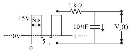
The charging voltage across a capacitor in a series RC circuit is given by $$V_c(t) = V_f + (V_i - V_f)e^{-t/\tau}$$, where the time constant is $$\tau = RC$$.
Phase 1 ($$0 \le t \le 5\ \mu\text{s}$$):
The input pulse of $$+5\text{ V}$$ is applied with $$V_i = 0\text{ V}$$:
$$V_o(5\ \mu\text{s}) = 5(1 - e^{-5/10}) = 5(1 - e^{-0.5}) \approx 5(1 - 0.6065) \approx 1.97\text{ V} \approx 2\text{ V}$$
Phase 2 ($$5\ \mu\text{s} < t \le 10\ \mu\text{s}$$):
The input source is open-circuited (high impedance), leaving no discharge path for the capacitor:
$$V_o(t) = 2\text{ V} \quad (\text{constant})$$
Phase 3 ($$10\ \mu\text{s} < t \le 15\ \mu\text{s}$$):
The second $$+5\text{ V}$$ pulse is applied with $$V_i = 2\text{ V}$$:
$$V_o(15\ \mu\text{s}) = 5 + (2 - 5)e^{-5/10} = 5 - 3e^{-0.5} \approx 5 - 3(0.6065) \approx 3.18\text{ V} \approx 3\text{ V}$$
Answer: Option (A): $$V_0(t)$$ rises to 2 V, holds its charge, and then rises further to 3 V.
Create a FREE account and get:
_1.webp)

Educational materials for JEE preparation

Ask our AI anything

AI can make mistakes. Please verify important information.
AI can make mistakes. Please verify important information.