Sign in
Please select an account to continue using cracku.in
↓ →
Join Our JEE Preparation Group
Prep with like-minded aspirants; Get access to free daily tests and study material.
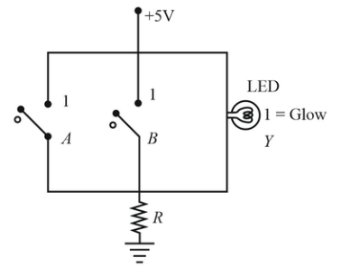
$$A = 0, B = 0$$: Neither path bypasses the indicator; current flows through the LED ($$Y = 1$$).
$$A = 1$$ and/or $$B = 1$$: The switch paths close, short-circuiting the voltage across the LED ($$Y = 0$$).
This inverse relationship ($$Y = \overline{A + B}$$) defines a NOR gate.

Click on the Email ☝️ to Watch the Video Solution
Create a FREE account and get:


Educational materials for JEE preparation

Ask our AI anything

AI can make mistakes. Please verify important information.
AI can make mistakes. Please verify important information.