Sign in
Please select an account to continue using cracku.in
↓ →
Join Our JEE Preparation Group
Prep with like-minded aspirants; Get access to free daily tests and study material.
For the given circuit the current $$i$$ through the battery when the key is closed and the steady state has been reached is:
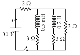
We need to determine the total steady-state current $$i$$ flowing through the battery after the key is closed.
When a DC circuit containing inductors reaches a steady-state condition (a long time after the switch is closed):
Based on the layout of this standard problem:
First, find the equivalent resistance ($$R_p$$) of the three parallel branches, where each active branch presents an individual resistance of $$3\ \Omega$$:
$$\frac{1}{R_p} = \frac{1}{3} + \frac{1}{3} + \frac{1}{3} = \frac{3}{3} = 1\ \Omega^{-1}$$
$$R_p = 1\ \Omega$$
Next, add the main line $$2\ \Omega$$ resistor that is connected in series with this entire parallel group to get the total circuit resistance:
$$R_{\text{eq}} = R_{\text{series}} + R_p = 2\ \Omega + 1\ \Omega = 3\ \Omega$$
Using Ohm’s Law ($$i = \frac{V}{R_{\text{eq}}}$$), we can compute the steady-state current leaving the battery:
$$i = \frac{30\text{ V}}{3\ \Omega} = 10\text{ A}$$
The current through the battery once the steady state has been reached is 10 A, which corresponds to Option A.
Create a FREE account and get:


Educational materials for JEE preparation

Ask our AI anything

AI can make mistakes. Please verify important information.
AI can make mistakes. Please verify important information.
