
Join Our JEE Preparation Group
Prep with like-minded aspirants; Get access to free daily tests and study material.
Sign in
Please select an account to continue using cracku.in
↓ →
Join Our JEE Preparation Group
Prep with like-minded aspirants; Get access to free daily tests and study material.
At very high frequencies, the effective impedance of the given circuit will be _________ $$\Omega$$.
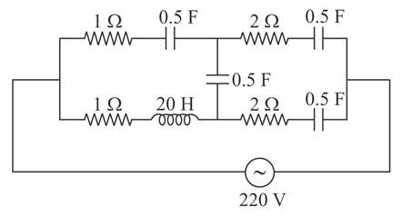
Correct Answer: 2
Based on the provided images, here is the formatted, step-by-step solution to the problem.
Problem Statement
At very high frequencies, find the effective impedance of the given AC circuit.
Step-by-Step Solution
To find the effective impedance at very high frequencies ($$f \to \infty$$), we need to evaluate how the reactive components (inductors and capacitors) behave.
1. Behavior of Capacitors at High Frequency
The capacitive reactance ($$X_C$$) is given by the formula:
$$X_C = \frac{1}{2\pi f C}$$
2. Behavior of Inductors at High Frequency
The inductive reactance ($$X_L$$) is given by the formula:
$$X_L = 2\pi f L$$
Simplified Circuit Analysis
Applying these conditions to the original network:
This leaves us with the following simplified equivalent circuit:
Calculating Equivalent Impedance ($$Z_{\text{eq}}$$)
The two $$2\ \Omega$$ resistors are in parallel. Their equivalent resistance ($$R_p$$) is:
$$R_p = \frac{2 \times 2}{2 + 2} = 1\ \Omega$$
This combination is in series with the remaining $$1\ \Omega$$ resistor:
$$Z_{\text{eq}} = 1\ \Omega + R_p = 1 + 1 = 2\ \Omega$$
Final Answer
The effective impedance of the given circuit at very high frequencies is $$2$$ $$\Omega$$.
Was this solution helpful?
Create a FREE account and get:
_1.webp)

Educational materials for JEE preparation

Ask our AI anything

AI can make mistakes. Please verify important information.
AI can make mistakes. Please verify important information.
