Join WhatsApp Icon JEE WhatsApp Group
Question 20

In the circuit, the logical value of $$A = 1$$ or $$B = 1$$ when potential at $$A$$ or $$B$$ is $$5 \text{ V}$$ and the logical value of $$A = 0$$ or $$B = 0$$ when potential at $$A$$ or $$B$$ is $$0 \text{ V}$$.

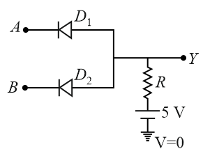
The truth table of the given circuit will be:

We need to determine the correct truth table for the given diode logic circuit.


1. Analyze the Circuit Components and Logic Levels

From the schematic :

  • The inputs $$A$$ and $$B$$ are connected to the cathodes (the pointy/bar side) of the ideal diodes $$D_1$$ and $$D_2$$.
  • The anodes (p-side) of both diodes are tied together to the output terminal $$Y$$.
  • The output terminal $$Y$$ is connected through a resistor $$R$$ to a $$+5\text{ V}$$ supply voltage.
  • Logical High (1): $$+5\text{ V}$$
  • Logical Low (0): $$0\text{ V}$$ (Ground)

2. Evaluate the State Combinations

  • Case 1: Both inputs are low ($$A = 0\text{ V}, B = 0\text{ V}$$)
    Both diodes have $$5\text{ V}$$ on their anode side (via resistor $$R$$) and $$0\text{ V}$$ on their cathode side. This makes both diodes forward-biased (conducting). They act as short circuits to ground, pulling the output voltage at $$Y$$ down to $$0\text{ V}$$.
    $$\implies \text{Output } Y = 0$$
  • Case 2: One input is low and the other is high ($$A = 5\text{ V}, B = 0\text{ V}$$ or $$A = 0\text{ V}, B = 5\text{ V}$$)
    The diode connected to the $$0\text{ V}$$ input becomes forward-biased and conducts, creating a direct path to ground. This forces the entire shared anode junction voltage down to $$0\text{ V}$$. The other diode (connected to $$5\text{ V}$$) will be reverse-biased (non-conducting).
    $$\implies \text{Output } Y = 0$$
  • Case 3: Both inputs are high ($$A = 5\text{ V}, B = 5\text{ V}$$)
    Both sides of the diodes are at a potential of $$5\text{ V}$$. Because there is no potential difference across them to turn them on, no current flows through the diodes (they remain non-conducting). Since no current flows through the resistor $$R$$, there is no voltage drop across it, leaving the output terminal $$Y$$ at the supply potential of $$+5\text{ V}$$.
    $$\implies \text{Output } Y = 1$$

3. Establish the Truth Table

The circuit behaves exactly like a standard digital AND gate:

$$A$$ $$B$$ $$Y$$
000
100
010
111

Conclusion

The truth table corresponds directly to Option A.

Get AI Help

Create a FREE account and get:

  • Free JEE Mains Previous Papers PDF
  • Take JEE Mains paper tests
Ask AI