Sign in
Please select an account to continue using cracku.in
↓ →
Join Our JEE Preparation Group
Prep with like-minded aspirants; Get access to free daily tests and study material.
In the circuit diagrams (A, B, C and D) shown below, R is a high resistance and S is a resistance of the order of galvanometer resistance G. The correct circuit, corresponding to the half deflection method for finding the resistance and figure of merit of the galvanometer, is the circuit labelled as:
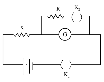
(a)
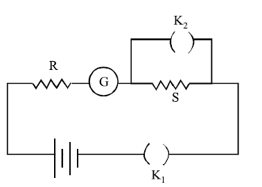
(b)
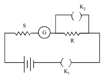
(c)
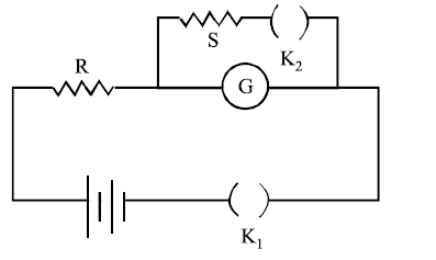
(d)
In Circuit (d), the high resistance $$R$$ is placed in series with the main circuit branch. The low resistance shunt $$S$$ (along with key $$K_2$$) is connected in parallel directly across the galvanometer $$G$$. This is the correct configuration.
$$I_g = \frac{V}{R + G}$$
$$\frac{I_g}{2} = I \cdot \left(\frac{S}{G+S}\right) = \left(\frac{V}{R + \frac{GS}{G+S}}\right) \cdot \frac{S}{G+S} = \frac{V \cdot S}{R(G+S) + GS}$$
$$\frac{1}{2}\left(\frac{V}{R+G}\right) = \frac{V \cdot S}{R \cdot G + R \cdot S + G \cdot S}$$
$$R \cdot G + R \cdot S + G \cdot S = 2 \cdot S(R + G)$$
$$R \cdot G - G \cdot S = R \cdot S \implies G(R - S) = R \cdot S$$
$$G = \frac{R \cdot S}{R - S}$$
Create a FREE account and get:


Educational materials for JEE preparation

Ask our AI anything

AI can make mistakes. Please verify important information.
AI can make mistakes. Please verify important information.
