Sign in
Please select an account to continue using cracku.in
↓ →
Join Our JEE Preparation Group
Prep with like-minded aspirants; Get access to free daily tests and study material.
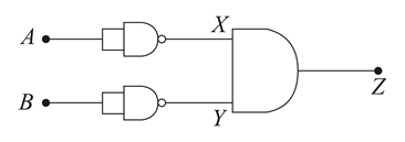
We need to determine the equivalent logic operation carried out by the given digital circuit arrangement.
From the schematic layout, the circuit consists of three logic gates connected in series:
When both input terminals of a NAND gate are shorted together, it functions strictly as an inverter (NOT gate):
$$X = \bar{A}$$
$$Y = \bar{B}$$
The signals $$X$$ and $$Y$$ serve as inputs to the final AND gate. The Boolean expression for the final output $$Z$$ is calculated as follows:
$$Z = X \cdot Y$$
Substituting the values of $$X$$ and $$Y$$ into the equation gives:
$$Z = \bar{A} \cdot \bar{B}$$
Applying De Morgan's Law ($$\bar{A} \cdot \bar{B} = \overline{A + B}$$), we can simplify the expression:
$$Z = \overline{A + B}$$
We can verify this Boolean expression by analyzing the state combinations of the truth table:
| $$A$$ | $$B$$ | $$X = \bar{A}$$ | $$Y = \bar{B}$$ | $$Z = X \cdot Y$$ |
|---|---|---|---|---|
| 0 | 0 | 1 | 1 | 1 |
| 0 | 1 | 1 | 0 | 0 |
| 1 | 0 | 0 | 1 | 0 |
| 1 | 1 | 0 | 0 | 0 |
The output truth value matches the standard operational behavior of a NOR logic gate, where the output is high ($1$) only when all inputs are low ($0$).
The logic operation carried out by the given circuit configuration is a NOR gate.
Create a FREE account and get:


Educational materials for JEE preparation

Ask our AI anything

AI can make mistakes. Please verify important information.
AI can make mistakes. Please verify important information.