Sign in
Please select an account to continue using cracku.in
↓ →
Join Our JEE Preparation Group
Prep with like-minded aspirants; Get access to free daily tests and study material.
In the given circuits (a) and (b), switches $$S_1$$ and $$S_2$$ are closed at $$t = 0$$ and kept close for a long time. The variation of currents in the two circuits for $$t \geq 0$$ are shown in the options. (Figures are schematic and not drawn to scale.)
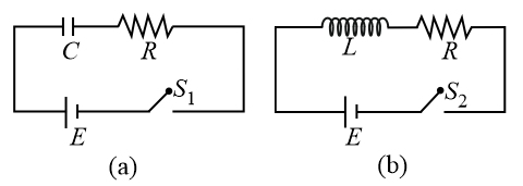
1. Analysis of Circuit (a): RC Series Circuit
In an RC circuit, when the switch $$S_1$$ is closed at $$t=0$$:
The current decays exponentially according to the equation: $$i_a(t) = \frac{E}{R} e^{-\frac{t}{RC}}$$
Curve must start at $$i = \frac{E}{R}$$ and approach $$0$$ as $$t$$ increases.
2. Analysis of Circuit (b): RL Series Circuit
In an RL circuit, when the switch $$S_2$$ is closed at $$t=0$$:
The current grows exponentially towards its steady-state value according to the equation: $$i_b(t) = \frac{E}{R} \left(1 - e^{-\frac{Rt}{L}}\right)$$
Curve must start at $$i = 0$$ and approach $$\frac{E}{R}$$ as $$t$$ increases.
Option (B) correctly depicts curve (a) as a decaying exponential starting from $$\frac{E}{R}$$ and curve (b) as a rising exponential approaching the steady-state value $$\frac{E}{R}$$
Create a FREE account and get:


Educational materials for JEE preparation

Ask our AI anything

AI can make mistakes. Please verify important information.
AI can make mistakes. Please verify important information.
