
Join Our JEE Preparation Group
Prep with like-minded aspirants; Get access to free daily tests and study material.
Sign in
Please select an account to continue using cracku.in
↓ →
Join Our JEE Preparation Group
Prep with like-minded aspirants; Get access to free daily tests and study material.
A bar magnet is passing through a conducting loop of radius $$R$$ with velocity $$v$$. The radius of the bar magnet is such that it just passes through the loop. The induced e.m.f. in the loop can be represented by the approximate curve:
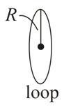
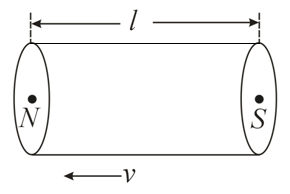
We need to determine the approximate curve representing the induced electromotive force (e.m.f.) in a conducting loop as a bar magnet passes completely through it with a constant velocity $$v$$.
According to Faraday's Law of Electromagnetic Induction, the magnitude of the induced e.m.f. ($$e$$) in a loop is directly proportional to the rate of change of magnetic flux ($$\Phi_B$$) through it:
$$e = -\frac{d\Phi_B}{dt}$$
The negative sign is a mathematical statement of Lenz's Law, which states that the induced current will flow in a direction that opposes the change in magnetic flux that produced it.
Let's divide the movement of the bar magnet through the loop into three distinct chronological phases:
As the North pole of the magnet moves closer to the loop, the magnetic flux linked with the loop increases ($$\frac{d\Phi_B}{dt} > 0$$). To oppose this increase, an e.m.f. is induced in one direction (let's consider this direction negative or positive, depending on orientation). The e.m.f. grows from zero to a peak value, and then decreases back to zero as the center of the magnet aligns with the loop.
When the magnet is fully inside the loop and moving uniformly, the number of magnetic field lines entering the loop is equal to the number of field lines leaving it. Consequently, the total magnetic flux remains constant ($$\frac{d\Phi_B}{dt} = 0$$), and the induced e.m.f. drops momentarily to zero.
As the South pole begins to leave the loop, the magnetic flux linked with the loop starts to decrease ($$\frac{d\Phi_B}{dt} < 0$$). According to Lenz's law, the loop tries to oppose this reduction by inducing an e.m.f. in the opposite direction to Phase 1. The e.m.f. rises to a peak in this reversed polarity and then drops back to zero as the magnet moves far away.
Based on our phase analysis, the ideal curve for the induced e.m.f. versus time must have the following properties:
This exact alternating behavior corresponds to the standard graphical representation found in option D.
Final Answer: Option D
Was this solution helpful?
Create a FREE account and get:
_1.webp)

Educational materials for JEE preparation

Ask our AI anything

AI can make mistakes. Please verify important information.
AI can make mistakes. Please verify important information.
