Sign in
Please select an account to continue using cracku.in
↓ →
Join Our JEE Preparation Group
Prep with like-minded aspirants; Get access to free daily tests and study material.
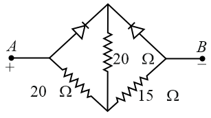
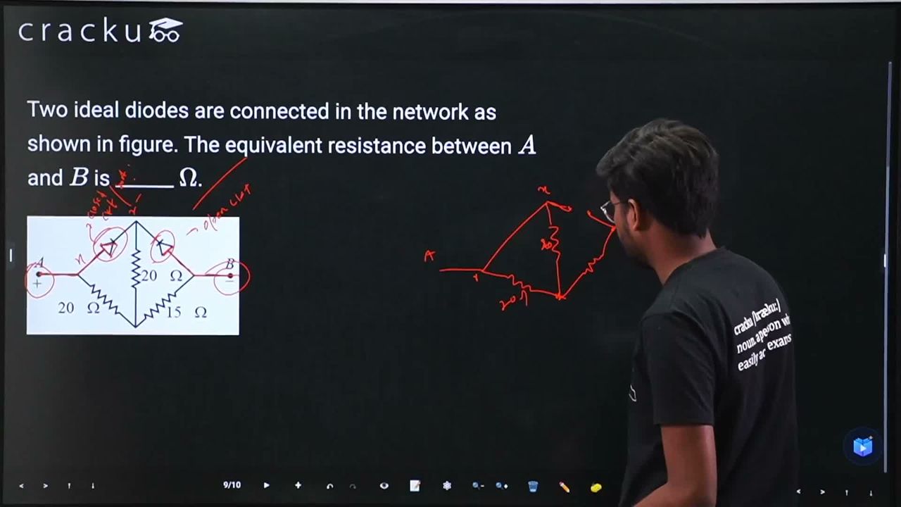
Two ideal diodes are connected in the network as shown in figure. The equivalent resistance between $$A$$ and $$B$$ is ______ $$\Omega$$.
Correct Answer: 25
We need to find the equivalent resistance between terminals $$A$$ and $$B$$ for the given diode-resistor network.
From the schematic shown , terminal $$A$$ is connected to the positive terminal ($$+$$) of the voltage source, and terminal $$B$$ is connected to the negative terminal ($$-$$).
Let's determine the bias state of each ideal diode based on the conventional current flowing from $$A$$ to $$B$$:
By substituting the forward-biased diode with a short circuit and removing the reverse-biased branch completely, the network simplifies significantly:
Let's calculate the equivalent resistance ($$R_p$$) of these two parallel $$20\ \Omega$$ resistors:
$$R_p = \frac{20 \times 20}{20 + 20} = \frac{400}{40} = 10\ \Omega$$
This parallel combination ($$R_p = 10\ \Omega$$) is in series with the remaining lower-right diagonal $$15\ \Omega$$ resistor leading straight to terminal $$B$$:
$$R_{AB} = R_p + 15\ \Omega$$
$$R_{AB} = 10\ \Omega + 15\ \Omega = 25\ \Omega$$
The equivalent resistance between $$A$$ and $$B$$ is 25 $$\Omega$$.
Click on the Email ☝️ to Watch the Video Solution
Create a FREE account and get:


Educational materials for JEE preparation

Ask our AI anything

AI can make mistakes. Please verify important information.
AI can make mistakes. Please verify important information.
