Sign in
Please select an account to continue using cracku.in
↓ →
Join Our JEE Preparation Group
Prep with like-minded aspirants; Get access to free daily tests and study material.
The plot given below is of the average power delivered to an LRC circuit versus frequency. The quality factor of the circuit is :
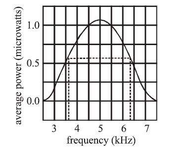
The lower cutoff frequency ($$f_1$$) is halfway between $$3.5$$ and $$4.0$$, which is $$3.75\text{ kHz}$$.
The upper cutoff frequency ($$f_2$$) is halfway between $$6.0$$ and $$6.5$$, which is $$6.25\text{ kHz}$$
$$\Delta f = f_2 - f_1 = 6.25\text{ kHz} - 3.75\text{ kHz} = 2.5\text{ kHz}$$
The maximum power occurs exactly at $$f_0 = 5\text{ kHz}$$
$$Q = \frac{f_0}{\Delta f}$$
$$Q = \frac{5\text{ kHz}}{2.5\text{ kHz}} = 2.0$$
Create a FREE account and get:


Educational materials for JEE preparation

Ask our AI anything

AI can make mistakes. Please verify important information.
AI can make mistakes. Please verify important information.
