Join Our JEE Preparation Group
Prep with like-minded aspirants; Get access to free daily tests and study material.
Sign in
Please select an account to continue using cracku.in
↓ →
Join Our JEE Preparation Group
Prep with like-minded aspirants; Get access to free daily tests and study material.
We need to determine the logic function represented by the given combination of logic gates.
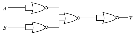
From the schematic on , let's trace the logic level from left to right:
The two gates at the input have their pins shorted together. A NOR gate with tied inputs functions exactly as a NOT gate.
The inverted inputs $$\overline{A}$$ and $$\overline{B}$$ are fed into a third NOR gate. The output expression at this stage is:
$$\text{Output}_{\text{mid}} = \overline{\overline{A} + \overline{B}}$$
Using De Morgan's Law ($$\overline{X + Y} = \overline{X} \cdot \overline{Y}$$):
$$\text{Output}_{\text{mid}} = \overline{\overline{A}} \cdot \overline{\overline{B}} = A \cdot B \quad \text{(An AND operation)}$$
The signal $$A \cdot B$$ passes through a final NOR gate that also has its inputs shorted together, acting as another NOT gate:
$$Y = \overline{A \cdot B}$$
The overall output Boolean expression is:
$$Y = \overline{A \cdot B}$$
This expression represents the standard logic operation of a NAND Gate.
The output of the given combination of gates represents a NAND Gate, which corresponds to Option B.
Was this solution helpful?
Click on the Email ☝️ to Watch the Video Solution
Create a FREE account and get:
_1.webp)

Educational materials for JEE preparation

Ask our AI anything

AI can make mistakes. Please verify important information.
AI can make mistakes. Please verify important information.