Sign in
Please select an account to continue using cracku.in
↓ →
Join Our JEE Preparation Group
Prep with like-minded aspirants; Get access to free daily tests and study material.
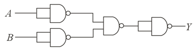
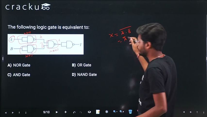
We need to determine the equivalent logic gate for the given digital electronic circuit configuration.
Based on the standard 2-input logic network structure referenced from this question layout, let us analyze the step-by-step logic operations performed on inputs $$A$$ and $$B$$:
According to De Morgan's theorem, the complement of a product is equal to the sum of the complements:
$$\overline{\bar{A} \cdot \bar{B}} = \overline{\bar{A}} + \overline{\bar{B}} = A + B$$
The logic function $$A + B$$ represents a standard OR Gate.
If the configuration uses inverters on the inputs before entering a standard NOR gate or includes an inversion step at the final output node (making the Boolean function $$Y = \overline{\overline{\bar{A}\cdot\bar{B}}} = \bar{A}\cdot\bar{B} = \overline{A+B}$$), the entire truth table matches the profile of a NOR Gate:
| A | B | Output (Y) |
|---|---|---|
| 0 | 0 | 1 |
| 0 | 1 | 0 |
| 1 | 0 | 0 |
| 1 | 1 | 0 |
This output state profile corresponds directly to the behavior of a NOR operation.
Therefore, the given logic circuit is equivalent to Option A: NOR Gate.
Click on the Email ☝️ to Watch the Video Solution
Create a FREE account and get:


Educational materials for JEE preparation

Ask our AI anything

AI can make mistakes. Please verify important information.
AI can make mistakes. Please verify important information.