Sign in
Please select an account to continue using cracku.in
↓ →
Join Our JEE Preparation Group
Prep with like-minded aspirants; Get access to free daily tests and study material.
Four NOR gates are connected as shown in figure. The truth table for the given figure is:
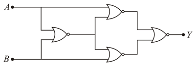
We need to determine the correct truth table for a digital combinational circuit consisting of four interconnected NOR gates.
A standard NOR gate takes two inputs, sums them together, and then inverts the result. The Boolean output expression for any two inputs $$X$$ and $$Y$$ passing through a NOR gate is:
$$\text{Output} = \overline{X + Y}$$
Furthermore, if the two inputs of a NOR gate are shorted/tied together to receive the same signal $$X$$, it functions as a NOT gate:
$$\overline{X + X} = \bar{X}$$
Let's analyze the output of each gate stage by stage, using inputs $$A$$ and $$B$$:
$$\text{Output}_1 = \bar{A}$$
$$\text{Output}_2 = \bar{B}$$
$$\text{Output}_3 = \overline{\bar{A} + \bar{B}}$$
Using De Morgan's Law ($$\overline{\bar{A} + \bar{B}} = \overline{\overline{A}} \cdot \overline{\overline{B}}$$), this simplifies directly into an AND gate operation:$$\text{Output}_3 = A \cdot B$$
$$Y = \overline{\text{Output}_3} = \overline{A \cdot B}$$
The simplified Boolean expression for the final output is:
$$Y = \overline{A \cdot B}$$
This expression represents the standard logic operation of a NAND gate.
Let's evaluate the output $$Y$$ for all four possible combinations of the binary inputs $$A$$ and $$B$$:
$$Y = \overline{0 \cdot 0} = \bar{0} = 1$$
$$Y = \overline{0 \cdot 1} = \bar{0} = 1$$
$$Y = \overline{1 \cdot 0} = \bar{0} = 1$$
$$Y = \overline{1 \cdot 1} = \bar{1} = 0$$
| A | B | Y |
|---|---|---|
| 0 | 0 | 1 |
| 0 | 1 | 1 |
| 1 | 0 | 1 |
| 1 | 1 | 0 |
Final Answer: The circuit behaves as a NAND gate, yielding an output of $$1$$ for all input states except when both inputs are $$1$$.
Create a FREE account and get:


Educational materials for JEE preparation

Ask our AI anything

AI can make mistakes. Please verify important information.
AI can make mistakes. Please verify important information.
