Join WhatsApp Icon JEE WhatsApp Group
Question 14

A conducting bar of length $$L$$ is free to slide on two parallel conducting rails as shown in the figure.


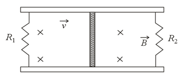
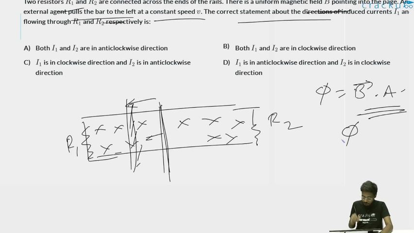
Two resistors $$R_1$$ and $$R_2$$ are connected across the ends of the rails. There is a uniform magnetic field $$\vec{B}$$ pointing into the page. An external agent pulls the bar to the left at a constant speed $$v$$. The correct statement about the directions of induced currents $$I_1$$ and $$I_2$$ flowing through $$R_1$$ and $$R_2$$ respectively is:

We need to determine the directions of the induced currents $$I_1$$ and $$I_2$$ flowing through the resistors $$R_1$$ and $$R_2$$ when a conducting bar is pulled to the left at a constant speed $$v$$ in a uniform magnetic field pointing into the page.

We can solve this problem using two well-established physics approaches: Lenz's Law and the Motional EMF (Right-Hand Rule) method.


Method 1: Using Lenz's Law (Magnetic Flux Approach)

Lenz's Law states that the direction of an induced current will always oppose the change in magnetic flux that produces it.

1. Left Loop containing Resistor $$R_1$$:

  • As the conducting bar moves to the left, the area of the left closed loop decreases.
  • Since the area decreases, the inward magnetic flux ($\otimes$) passing through this loop decreases.
  • To oppose this decrease, the induced current $$I_1$$ must create its own magnetic field pointing into the page ($\otimes$) to reinforce the original field.
  • According to the right-hand grip rule, a magnetic field pointing into the page corresponds to a clockwise current direction.

2. Right Loop containing Resistor $$R_2$$:

  • As the conducting bar moves to the left, the area of the right closed loop increases.
  • Since the area increases, the inward magnetic flux ($\otimes$) passing through this loop increases.
  • To oppose this increase, the induced current $$I_2$$ must create its own magnetic field pointing out of the page ($\odot$) to cancel out the excess field.
  • According to the right-hand grip rule, a magnetic field pointing out of the page corresponds to an anticlockwise current direction.

Method 2: Using Motional EMF ($\vec{v} \times \vec{B}$)

When the conducting rod moves through the magnetic field, the free charges inside the rod experience a magnetic Lorentz force given by $$\vec{F} = q(\vec{v} \times \vec{B})$$.

  • The velocity vector $$\vec{v}$$ points to the left ($\leftarrow$).
  • The magnetic field vector $$\vec{B}$$ points into the page ($\otimes$).
  • Using the right-hand rule for the cross product $$\vec{v} \times \vec{B}$$, pointing your fingers to the left and curling them into the page causes your thumb to point downwards ($\downarrow$).
  • This means positive charge carriers are driven to the bottom end of the bar, making the bottom end positive and the top end negative. The moving bar behaves exactly like a battery with its positive terminal at the bottom.

Now, tracing how this "battery" drives current through each parallel loop:

  • For the left loop ($$R_1$$), the current leaves the positive bottom terminal, moves left through the bottom rail, goes up through $$R_1$$, and returns right to the negative top terminal. This forms a clockwise loop.
  • For the right loop ($$R_2$$), the current leaves the positive bottom terminal, moves right through the bottom rail, goes up through $$R_2$$, and returns left to the negative top terminal. This forms an anticlockwise loop.

Conclusion

Both methods yield the same consistent result:

  • $$I_1$$ is in the clockwise direction.
  • $$I_2$$ is in the anticlockwise direction.

Therefore, the correct answer is Option C: $$I_1$$ is in clockwise direction and $$I_2$$ is in anticlockwise direction.

Get AI Help

Create a FREE account and get:

  • Free JEE Mains Previous Papers PDF
  • Take JEE Mains paper tests
Ask AI