Sign in
Please select an account to continue using cracku.in
↓ →
Join Our JEE Preparation Group
Prep with like-minded aspirants; Get access to free daily tests and study material.
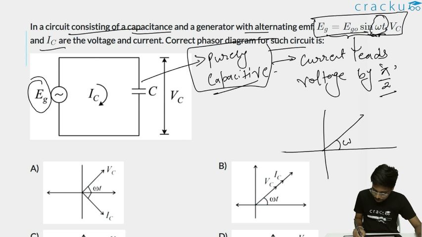
In a circuit consisting of a capacitance and a generator with alternating emf, $$E_g = E_{go}\sin\omega t$$, $$V_C$$ and $$I_C$$ are the voltage and current. Correct phasor diagram for such circuit is:
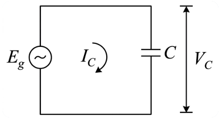
In a purely capacitive circuit with $$E_g = E_{g0}\sin\omega t$$, the current leads the voltage by $$90°$$. This is because in a capacitor, charge builds up as voltage rises, and maximum current flows when the voltage is zero (rate of change is maximum), while zero current flows when the voltage is at its peak.
Specifically, the current is: $$I_C = I_0\sin\left(\omega t + \frac{\pi}{2}\right) = I_0\cos(\omega t)$$
while the voltage across the capacitor is $$V_C = V_0\sin(\omega t)$$ (in phase with the applied emf).
In the phasor diagram, $$V_C$$ (or the emf $$E_g$$) is taken as the reference phasor, and $$I_C$$ leads $$V_C$$ by $$90°$$ (i.e., $$I_C$$ is drawn $$90°$$ ahead of $$V_C$$ in the direction of rotation). The correct phasor diagram shows $$I_C$$ perpendicular to and leading $$V_C$$, which corresponds to phasor diagram (3).
Click on the Email ☝️ to Watch the Video Solution
Create a FREE account and get:


Educational materials for JEE preparation

Ask our AI anything

AI can make mistakes. Please verify important information.
AI can make mistakes. Please verify important information.
