Sign in
Please select an account to continue using cracku.in
↓ →
Join Our JEE Preparation Group
Prep with like-minded aspirants; Get access to free daily tests and study material.
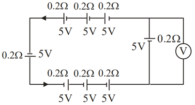
Total cells in the main loop aiding the same current direction:
$$n = 3 \text{ (top)} + 1 \text{ (left)} + 3 \text{ (bottom)} = 7$$
Total loop EMF and resistance:
$$E_{\text{total}} = 7 \times 5 = 35\text{ V}$$
$$r_{\text{total}} = 7 \times 0.2 = 1.4\ \Omega$$
Loop current:
$$I = \frac{E_{\text{total}}}{r_{\text{total}}} = \frac{35}{1.4} = 25\text{ A}$$
Terminal voltage across the rightmost branch cell: $$V = E - Ir \implies V = 5 - (25 \times 0.2) = 0\text{ V}$$
Create a FREE account and get:


Educational materials for JEE preparation

Ask our AI anything

AI can make mistakes. Please verify important information.
AI can make mistakes. Please verify important information.