Sign in
Please select an account to continue using cracku.in
↓ →
Join Our JEE Preparation Group
Prep with like-minded aspirants; Get access to free daily tests and study material.
The figure shows a circuit that contains four identical resistors with resistance $$R = 2.0$$ $$\Omega$$, two identical inductors with inductance $$L = 2.0$$ mH and an ideal battery with E.M.F. $$E = 9$$ V. The current $$i$$ just after the switch $$S$$ is closed will be:
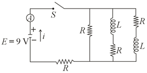
An inductor opposes sudden changes in the electrical current passing through it due to Lenz's law. When the switch $$S$$ is closed at time $$t = 0$$ (initial transient state):
Let's evaluate the status of the branches containing inductors immediately after closing the switch:
Removing these two open-circuited branches leaves only the active conductive paths containing resistors:
These two remaining active resistors are connected in a simple single-loop series configuration across the ideal battery source.
Since the two active resistors are connected end-to-end in series, their individual resistance values add up linearly:
$$R_{\text{eq}} = R + R = 2.0 \,\, \Omega + 2.0 \,\, \Omega = 4.0 \,\, \Omega$$
Using Ohm's Law, we can calculate the total current $$i$$ delivered by the battery with E.M.F. $$E = 9 \,\, \text{V}$$ into this simplified network at $$t = 0^+$$:
$$i = \frac{E}{R_{\text{eq}}}$$
$$i = \frac{9 \,\, \text{V}}{4.0 \,\, \Omega} = 2.25 \,\, \text{A}$$
Correct Option: C ($$2.25 \,\, \text{A}$$)
Click on the Email ☝️ to Watch the Video Solution
Create a FREE account and get:


Educational materials for JEE preparation

Ask our AI anything

AI can make mistakes. Please verify important information.
AI can make mistakes. Please verify important information.
