Sign in
Please select an account to continue using cracku.in
↓ →
Join Our JEE Preparation Group
Prep with like-minded aspirants; Get access to free daily tests and study material.
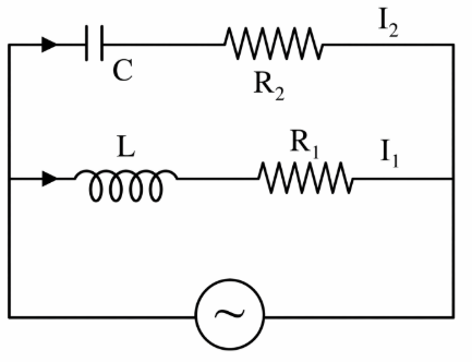
In the above circuit, $$C = \frac{\sqrt{3}}{2}\mu F$$, $$R_2 = 20 \Omega$$, $$L = \frac{\sqrt{3}}{10} H$$ and $$R_1 = 10 \Omega$$. Current in $$L$$-$$R_1$$ path is $$I_1$$ and in C-$$R_2$$ path it is $$I_2$$. The voltage of AC source is given by, $$V = 200\sqrt{2} \sin(100t)$$ volts. The phase difference between $$I_1$$ and $$I_2$$ is:
We first note that the source voltage is written as $$V = 200\sqrt{2}\,\sin(100t)$$. Comparing this with the standard form $$V = V_{0}\sin(\omega t)$$ we can at once read the angular frequency as $$\omega = 100\;{\rm rad\,s^{-1}}.$$
There are two independent series branches connected across this same source.
Branch 1 (R-L branch)
The impedance of a resistor $$R_1$$ in series with an inductor $$L$$ is, by definition,
$$Z_1 = R_1 + j\omega L,$$
where the symbol $$j$$ stands for $$\sqrt{-1}$$ (conventional electrical engineering notation).
Substituting the numerical data
$$R_1 = 10\;\Omega,\qquad L = \frac{\sqrt{3}}{10}\;{\rm H},\qquad \omega = 100\;{\rm rad\,s^{-1}},$$
we obtain
$$\omega L \;=\; 100 \times \frac{\sqrt{3}}{10}\;=\;10\sqrt{3}\;\Omega.$$
Hence
$$Z_1 = 10 + j\,10\sqrt{3}\;\Omega.$$
The phase angle by which the branch current lags its voltage for an R-L circuit is given by the well-known relation
$$\phi_1 = \tan^{-1}\!\Bigl(\frac{\omega L}{R_1}\Bigr).$$
Substituting,
$$\phi_1 \;=\; \tan^{-1}\!\Bigl(\frac{10\sqrt{3}}{10}\Bigr) \;=\; \tan^{-1}(\sqrt{3}) \;=\; 60^{\circ}.$$
Because the term $$+j\omega L$$ is inductive, this angle represents lag. Therefore
$$I_1 \;\text{lags}\; V \;\text{by}\; 60^{\circ},$$
or equivalently, the phase of $$I_1$$ is
$$\angle I_1 = -60^{\circ}.$$
Branch 2 (R-C branch)
The impedance of a resistor $$R_2$$ in series with a capacitor $$C$$ is
$$Z_2 = R_2 - \dfrac{j}{\omega C}.$$
Using the given values
$$R_2 = 20\;\Omega,\qquad C = \frac{\sqrt{3}}{2}\,\mu{\rm F} = \frac{\sqrt{3}}{2}\times 10^{-6}\;{\rm F},$$
we first compute the capacitive reactance $$X_C$$:
$$\omega C = 100 \times \frac{\sqrt{3}}{2}\times 10^{-6} \;=\; 50\sqrt{3}\times 10^{-6}.$$
Taking the reciprocal,
$$X_C \;=\; \frac{1}{\omega C} \;=\; \frac{1}{50\sqrt{3}\times 10^{-6}} \;=\; \frac{10^{6}}{50\sqrt{3}} \;=\; \frac{20\,000}{\sqrt{3}}\;\Omega \;=\; \frac{20\,000\sqrt{3}}{3}\;\Omega.$$
For later numerical clarity we also write
$$X_C \;\approx\; 11\,546.7\;\Omega.$$
Thus
$$Z_2 = 20 \;-\; j\,X_C = 20 - j\,11\,546.7\;\Omega.$$
The phase angle of the current with respect to the voltage for an R-C series circuit is given by
$$\phi_2 = \tan^{-1}\!\Bigl(\frac{X_C}{R_2}\Bigr),$$
and because the reactance term carries a minus sign, this angle represents a lead (capacitive currents lead the voltage).
Substituting,
$$\phi_2 \;=\; \tan^{-1}\!\Bigl(\frac{11\,546.7}{20}\Bigr) \;=\; \tan^{-1}(577.335) \;\approx\; 89.9^{\circ}.$$
To a very good approximation we may treat this as exactly
$$\angle I_2 = +90^{\circ}\;,$$
i.e. the current $$I_2$$ leads the source voltage by $$90^{\circ}.$$
Phase difference between the two branch currents
The current $$I_1$$ has phase $$-60^{\circ}$$, while $$I_2$$ has phase $$+90^{\circ}$$. The absolute phase difference $$\Delta\phi$$ is therefore
$$\Delta\phi = (+90^{\circ}) - (-60^{\circ}) = 90^{\circ} + 60^{\circ} = 150^{\circ}.$$
This is the required result.
Hence, the correct answer is Option D.
Create a FREE account and get:


Educational materials for JEE preparation

Ask our AI anything

AI can make mistakes. Please verify important information.
AI can make mistakes. Please verify important information.
