Sign in
Please select an account to continue using cracku.in
↓ →
Join Our JEE Preparation Group
Prep with like-minded aspirants; Get access to free daily tests and study material.
In the figure is shown a system of four capacitors connected across a 10 V battery. The charge that will flow from switch S when it is closed is:
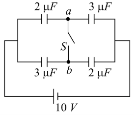
We first read the values written on the four capacitors in the figure. Moving clockwise from the positive terminal of the battery we have
$$C_1 = 1\;\mu{\rm F}$$, $$\; C_2 = 2\;\mu{\rm F}$$, $$\; C_3 = 2\;\mu{\rm F}$$, $$\; C_4 = 1\;\mu{\rm F}.$$
The battery maintains the upper horizontal conductor at $$+10\;{\rm V}$$ while the lower horizontal conductor is at $$0\;{\rm V}.$$ The internal junctions are
$$a\;{\rm (between}\;C_1\;{\rm and}\;C_2), \qquad b\;{\rm (between}\;C_3\;{\rm and}\;C_4).$$
At the start the switch $$S$$ between $$a$$ and $$b$$ is OPEN, so the two branches charge independently.
1. Charging of the left branch (with the switch open).
The two capacitors $$C_1$$ and $$C_2$$ are in series, so the same charge $$Q_L$$ flows through each. The equivalent capacitance of the branch is
$$C_{\,{\rm eqL}}=\frac{C_1C_2}{C_1+C_2} =\frac{(1)(2)}{1+2} =\frac{2}{3}\;\mu{\rm F}.$$
The battery is across this equivalent capacitance, hence
$$Q_L = C_{\,{\rm eqL}}\;V =\left(\frac{2}{3}\right)\times 10 = 6.667\;\mu{\rm C}.$$
Because $$Q=CV,$$ the individual voltage drops are
$$V_{C_1}=\frac{Q_L}{C_1}=\frac{6.667}{1}=6.667\;{\rm V},\qquad V_{C_2}=\frac{Q_L}{C_2}=\frac{6.667}{2}=3.333\;{\rm V}.$$
Hence the potential of junction $$a$$ (which is the lower plate of $$C_1$$ and the upper plate of $$C_2$$) is
$$V_a = 10- V_{C_1}=10-6.667 = 3.333\;{\rm V}.$$
2. Charging of the right branch (with the switch open).
Exactly the same reasoning gives for the right branch
$$C_{\,{\rm eqR}}=\frac{C_3C_4}{C_3+C_4} =\frac{(2)(1)}{2+1} =\frac{2}{3}\;\mu{\rm F},$$
so
$$Q_R=C_{\,{\rm eqR}}\;V =\left(\frac{2}{3}\right)\times10 =6.667\;\mu{\rm C}.$$
The individual drops are
$$V_{C_3}=\frac{Q_R}{C_3}=\frac{6.667}{2}=3.333\;{\rm V},\qquad V_{C_4}=\frac{Q_R}{C_4}=\frac{6.667}{1}=6.667\;{\rm V},$$
so the potential of junction $$b$$ is
$$V_b = 10- V_{C_3}=10-3.333 = 6.667\;{\rm V}.$$
Thus, before the switch is closed we have
$$V_b - V_a = 6.667 - 3.333 = 3.334\;{\rm V}\;(\approx 10/3\;{\rm V}).$$
3. Situation immediately after closing the switch.
Closing $$S$$ connects the two junctions, forcing their common potential to a single value, say $$V_f.$$
Because the conducting strip has negligible resistance, no appreciable potential difference can remain along it, so
$$V_f = V_a' = V_b'.$$
The four capacitors are now arranged as follows:
Let us use charge conservation at the combined node. At that node the algebraic sum of the charges on the four plates which touch it must remain zero, because the conductor was initially neutral and it is not connected to the battery. Writing the charges on those plates after equilibrium:
$$-C_1(10-V_f) - C_3(10-V_f) + C_2V_f + C_4V_f = 0.$$
Simplifying gives
$$-(C_1+C_3)(10-V_f)+(C_2+C_4)V_f=0,$$
and therefore
$$V_f=\frac{10(C_1+C_3)}{C_1+C_2+C_3+C_4} =\frac{10(1+2)}{1+2+2+1} =\frac{30}{6}=5\;{\rm V}.$$
4. New charges on the capacitors.
Applying $$Q = CV$$ again with the new voltages we obtain
$$Q_{1}' = C_1(10-V_f)=1(10-5)=5\;\mu{\rm C},$$ $$Q_{2}' = C_2V_f =2(5)=10\;\mu{\rm C},$$ $$Q_{3}' = C_3(10-V_f)=2(10-5)=10\;\mu{\rm C},$$ $$Q_{4}' = C_4V_f =1(5)=5\;\mu{\rm C}.$$
(The primes denote charges after the switch is closed. A positive value means the plate touching the junction carries positive charge; a negative value would mean negative charge.)
5. Charge that has to pass through the switch.
Only charges situated on the plates that meet at $$a$$ and $$b$$ can flow from one junction to the other; the plates attached to the battery cannot. So we look at the change suffered by the junction plates:
At $$a$$ (the plate of $$C_2$$ and the plate of $$C_1$$):
Initial charge = $$(+6.667)\;+\;(-6.667)=0,$$
Final charge = $$(+10)\;+\;(-5)=+5\;\mu{\rm C}.$$
Thus $$a$$ has gained $$+5\;\mu{\rm C}.$$
At $$b$$ (the plate of $$C_4$$ and the plate of $$C_3$$):
Initial charge = $$(+6.667)\;+\;(-6.667)=0,$$
Final charge = $$(+5)\;+\;(-10)=-5\;\mu{\rm C}.$$
Thus $$b$$ has lost $$5\;\mu{\rm C}.$$
Because the only path joining the two points is the wire of the switch, the same $$5\;\mu{\rm C}$$ must have travelled from the higher-potential junction $$b$$ to the lower-potential junction $$a$$ to equalise them.
6. Direction.
Before closing, $$V_b > V_a,$$ so positive charge naturally flows from $$b$$ towards $$a,$$ exactly the direction stated in Option C.
Hence, the correct answer is Option C.
Create a FREE account and get:


Educational materials for JEE preparation

Ask our AI anything

AI can make mistakes. Please verify important information.
AI can make mistakes. Please verify important information.
