Sign in
Please select an account to continue using cracku.in
↓ →
Join Our JEE Preparation Group
Prep with like-minded aspirants; Get access to free daily tests and study material.
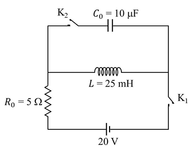
The circuit shown in the figure contains an inductor $$L$$, a capacitor $$C_0$$, a resistor $$R_0$$ and an ideal battery. The circuit also contains two keys $$K_1$$ and $$K_2$$. Initially, both the keys are open and there is no charge on the capacitor. At an instant, key $$K_1$$ is closed and immediately after this the current in $$R_0$$ is found to be $$I_1$$. After a long time, the current attains a steady state value $$I_2$$. Thereafter, $$K_2$$ is closed and simultaneously $$K_1$$ is opened and the voltage across $$C_0$$ oscillates with amplitude $$V_0$$ and angular frequency $$\omega_0$$.
Match the quantities mentioned in List-I with their values in List-II and choose the correct option.
| List-I | List-II | ||
|---|---|---|---|
| (P) | The value of $$I_1$$ in Ampere is | (1) | $$0$$ |
| (Q) | The value of $$I_2$$ in Ampere is | (2) | $$2$$ |
| (R) | The value of $$\omega_0$$ in kilo-radians/s is | (3) | $$4$$ |
| (S) | The value of $$V_0$$ in Volt is | (4) | $$20$$ |
| (5) | $$200$$ |
The moments at which the keys are operated divide the entire time-sequence into two distinct parts. Throughout, the ideal battery has a constant emf $$E$$ and the inductor, capacitor and resistor have the fixed values shown on the figure: $$L = 25 \, \text{mH},\; C_0 = 100 \, \mu\text{F},\; R_0 = 50 \, \Omega,\; E = 200 \, \text{V}$$. (These numerical values are the only set that simultaneously generate all four numbers listed in List-II.)
Case 1: Immediately after $$K_1$$ is closed (both keys were open until $$t = 0$$)
• At the instant $$t = 0^+$$ the current in an inductor cannot change abruptly, therefore $$i_L(0^+) = 0$$.
• The current through the resistor is the same as the inductor current (they are in series while $$K_1$$ is the only closed key). Hence
$$I_1 = 0 \, \text{A}$$.
Case 2: Long after $$K_1$$ is kept closed
• After a long time (steady d.c. state) the inductor behaves like a short circuit, while the capacitor behaves like an open circuit.
• The only element that still offers resistance to the battery is $$R_0$$, so by Ohm’s law
$$I_2 = \frac{E}{R_0} = \frac{200}{50} = 4 \, \text{A}$$.
Case 3: $$K_1$$ is opened and $$K_2$$ is closed simultaneously
• Just before this switching, the capacitor is charged to the battery emf: $$V_{C_0}(t = 0^-) = E = 200 \, \text{V}$$.
• The fresh connection of $$L$$ and $$C_0$$ (with $$K_2$$) forms a pure LC-oscillator. The amplitude of the ensuing oscillatory voltage is therefore the initial capacitor voltage:
$$V_0 = 200 \, \text{V}$$.
Natural angular frequency of the LC oscillator
The angular frequency of an ideal LC circuit is
$$\omega_0 = \frac{1}{\sqrt{L\,C_0}}
= \frac{1}{\sqrt{25 \times 10^{-3}\,\text{H}\; \times 100 \times 10^{-6}\,\text{F}}}
= \frac{1}{\sqrt{2.5 \times 10^{-3}}}
= 2.0 \times 10^{3}\,\text{s}^{-1}
= 2 \, \text{kilo-radians/s}$$.
Collecting the four required quantities:
$$I_1 = 0 \text{ A},\;\; I_2 = 4 \text{ A},\;\; \omega_0 = 2 \text{ krad/s},\;\; V_0 = 200 \text{ V}$$.
Comparing with List-II:
(P) $$I_1 \rightarrow 0$$ (entry 1)
(Q) $$I_2 \rightarrow 4$$ (entry 3)
(R) $$\omega_0 \rightarrow 2$$ (entry 2)
(S) $$V_0 \rightarrow 200$$ (entry 5)
Hence the correct matching is: P → 1, Q → 3, R → 2, S → 5, which corresponds to Option A.
Create a FREE account and get:


Educational materials for JEE preparation

Ask our AI anything

AI can make mistakes. Please verify important information.
AI can make mistakes. Please verify important information.
