Sign in
Please select an account to continue using cracku.in
↓ →
Join Our JEE Preparation Group
Prep with like-minded aspirants; Get access to free daily tests and study material.
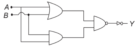
Let the two external inputs be labelled as $$A$$ and $$B$$.
Step 1 - Identify each block in the diagram.
• Each small triangle with a bubble at its output is an INVERTER (NOT gate).
• The larger gate whose symbol has a curved input side and a bubble at its output is a NOR gate.
Step 2 - Write the Boolean expression of every stage.
• Output of the first inverter is $$\overline{A}$$.
• Output of the second inverter is $$\overline{B}$$.
• The NOR gate receives $$\overline{A}$$ and $$\overline{B}$$, so its output $$Y$$ is
$$Y = \overline{\overline{A} + \overline{B}} \quad -(1)$$
Step 3 - Simplify the expression using De Morgan’s theorem.
De Morgan’s theorem states
$$\overline{X + Z} = \overline{X} \cdot \overline{Z}$$
Applying this to $$(1)$$ with $$X = \overline{A}$$ and $$Z = \overline{B}$$ gives
$$Y = \overline{\overline{A}} \cdot \overline{\overline{B}}$$
Since a double negation cancels, $$\overline{\overline{A}} = A$$ and $$\overline{\overline{B}} = B$$. Hence
$$Y = A \cdot B$$
Step 4 - Interpret the final Boolean result.
The output expression $$Y = A \cdot B$$ is the logical AND of the inputs.
Therefore, the overall operation performed by the given circuit is an AND gate.
Option B (AND) is correct.
Create a FREE account and get:


Educational materials for JEE preparation

Ask our AI anything

AI can make mistakes. Please verify important information.
AI can make mistakes. Please verify important information.