Sign in
Please select an account to continue using cracku.in
↓ →
Join Our JEE Preparation Group
Prep with like-minded aspirants; Get access to free daily tests and study material.
A logic gate circuit has two inputs $$A$$ and $$B$$ and output $$Y$$. The voltage waveforms of $$A$$, $$B$$ and $$Y$$ are shown. The logic gate circuit is
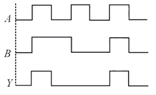
We need to identify the logic gate from the voltage waveforms of inputs $$A$$, $$B$$ and output $$Y$$.
From the waveforms, let us construct the truth table by reading the HIGH (1) and LOW (0) values of $$A$$, $$B$$, and $$Y$$ at each time interval:
Interval 1: $$A = 0, B = 0 \Rightarrow Y = 0$$
Interval 2: $$A = 1, B = 0 \Rightarrow Y = 0$$
Interval 3: $$A = 1, B = 1 \Rightarrow Y = 1$$
Interval 4: $$A = 0, B = 1 \Rightarrow Y = 0$$
Now let us compare this with the truth tables of the given gates:
AND gate truth table:
$$A = 0, B = 0 \Rightarrow Y = 0$$
$$A = 1, B = 0 \Rightarrow Y = 0$$
$$A = 1, B = 1 \Rightarrow Y = 1$$
$$A = 0, B = 1 \Rightarrow Y = 0$$
The output $$Y$$ is HIGH only when both $$A$$ and $$B$$ are HIGH. This matches perfectly with the AND gate truth table.
The correct answer is Option A: AND gate.

Click on the Email ☝️ to Watch the Video Solution
Create a FREE account and get:


Educational materials for JEE preparation

Ask our AI anything

AI can make mistakes. Please verify important information.
AI can make mistakes. Please verify important information.
