Sign in
Please select an account to continue using cracku.in
↓ →
Join Our JEE Preparation Group
Prep with like-minded aspirants; Get access to free daily tests and study material.
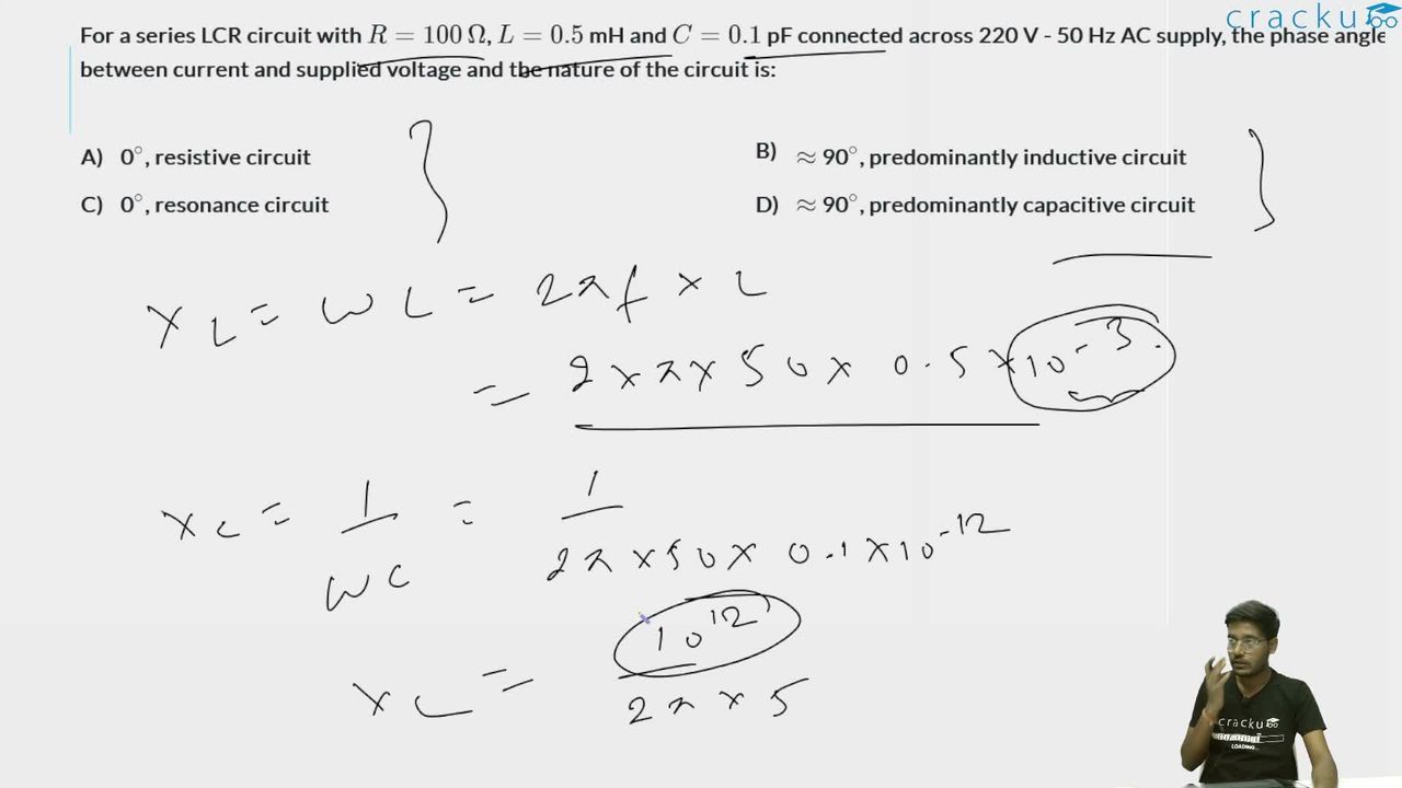
For a series LCR circuit with $$R = 100$$ $$\Omega$$, $$L = 0.5$$ mH and $$C = 0.1$$ pF connected across 220 V - 50 Hz AC supply, the phase angle between current and supplied voltage and the nature of the circuit is:
For a series LCR circuit, the inductive reactance is $$X_L = 2\pi f L = 2\pi \times 50 \times 0.5 \times 10^{-3} \approx 0.157 \,\Omega$$.
The capacitive reactance is $$X_C = \frac{1}{2\pi f C} = \frac{1}{2\pi \times 50 \times 0.1 \times 10^{-12}} \approx 3.18 \times 10^{10} \,\Omega$$.
Since $$X_C \gg X_L$$, the net reactance is dominantly capacitive. The phase angle between the voltage and the current is given by $$\tan\phi = \frac{X_L - X_C}{R}$$. Here $$X_L - X_C \approx -3.18 \times 10^{10} \,\Omega$$ and $$R = 100 \,\Omega$$, so $$\tan\phi \approx -3.18 \times 10^8$$, giving $$\phi \approx -90^\circ$$. The negative sign means the current leads the voltage by $$\approx 90^\circ$$, which is characteristic of a predominantly capacitive circuit.
Therefore the phase angle between current and supplied voltage is $$\approx 90^\circ$$ and the circuit is predominantly capacitive.
Click on the Email ☝️ to Watch the Video Solution
Create a FREE account and get:


Educational materials for JEE preparation

Ask our AI anything

AI can make mistakes. Please verify important information.
AI can make mistakes. Please verify important information.
