Sign in
Please select an account to continue using cracku.in
↓ →
Join Our JEE Preparation Group
Prep with like-minded aspirants; Get access to free daily tests and study material.
A potential divider circuit is shown in the figure below. The output voltage $$V_0$$ is
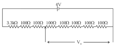
Since all resistors are connected in series,
$$R_{total} = 3300\Omega + (7 \times 100\Omega)$$
$$R_{total} = 3300\Omega + 700\Omega = 4000\Omega$$
The measurement for $$V_0$$ begins after the $$3.3\text{ k}\Omega$$ and the first two $$100\Omega$$ resistors.
The measurement includes the remaining five $$100\Omega$$ resistors.
$$R_{out} = 5 \times 100\Omega = 500\Omega$$
$$V_0 = V_{in} \cdot \left( \frac{R_{out}}{R_{total}} \right)$$
$$V_0 = 4\text{ V} \cdot \left( \frac{500\Omega}{4000\Omega} \right)$$
$$V_0 = 0.5\text{ V}$$
Click on the Email ☝️ to Watch the Video Solution
Create a FREE account and get:


Educational materials for JEE preparation

Ask our AI anything

AI can make mistakes. Please verify important information.
AI can make mistakes. Please verify important information.
