Sign in
Please select an account to continue using cracku.in
↓ →
Join Our JEE Preparation Group
Prep with like-minded aspirants; Get access to free daily tests and study material.
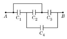
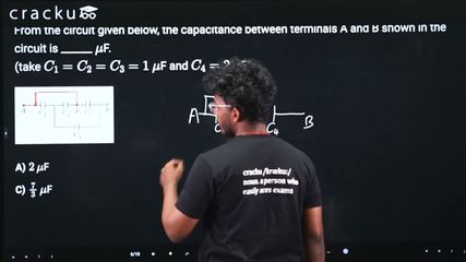
From the circuit given below, the capacitance between terminals A and B shown in the circuit is ______ $$\mu$$F.
(take $$C_1 = C_2 = C_3 = 1$$ $$\mu$$F and $$C_4 = 2$$ $$\mu$$F.)
Let the node between $$C_1$$ and $$C_2$$ be P.
The node between $$C_2$$ and $$C_3$$ is A (since that is shorted)
The two capacitors $$C_1 , C_2 $$ are connected end-to-end between the terminals A and P, so they are in parallel.
The simplified circuit looks like
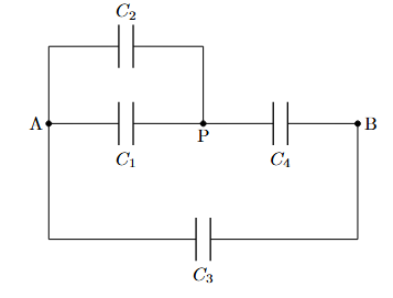
$$(C_1 \parallel C_2) \text{ in series with } C_4$$
$$\text{and the above eq. cap in parallel with } C_3$$
$$C_{eq} = \frac{(C_1 + C_2)C_4}{(C_1 + C_2) + C_4} + C_3$$
$$= \frac{(1 + 1)(2)}{1 + 1 + 2} + 1$$
$$= \frac{4}{4} + 1$$
$$= 2\mu F$$
Option C which is: $$2,\mu F$$
Click on the Email ☝️ to Watch the Video Solution
Create a FREE account and get:


Educational materials for JEE preparation

Ask our AI anything

AI can make mistakes. Please verify important information.
AI can make mistakes. Please verify important information.
