Sign in
Please select an account to continue using cracku.in
↓ →
Join Our JEE Preparation Group
Prep with like-minded aspirants; Get access to free daily tests and study material.
A common emitter amplifier circuit, built using an NPN transistor, is shown in the figure. Its dc current gain is 250, $$R_C = 1$$ k$$\Omega$$ and $$V_{CC} = 10$$ V. The minimum base current for $$V_{CE}$$ to reach saturation is:
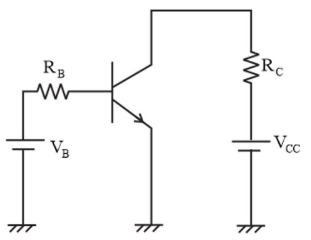
In a common emitter amplifier using an NPN transistor, the saturation state and base current are calculated as follows:
At the saturation state, the collector-emitter voltage $$V_{CE}$$ reaches its minimum value (approximately zero).
The collector current $$I_C$$ is determined by:
$$I_C = \frac{V_{CC}}{R_C}$$
Substituting the given values ($$V_{CC} = 10\text{ V}$$ and $$R_C = 1\text{ k}\Omega$$):
$$I_C = \frac{10\text{ V}}{1000\ \Omega} = 10\text{ mA}$$
The relationship between collector current and base current is defined by the DC current gain ($$\beta$$):
$$\beta = \frac{I_C}{I_B}$$
Rearranging to solve for the minimum base current $$I_B$$:
$$I_B = \frac{I_C}{\beta}$$
Substituting $$I_C = 10\text{ mA}$ and $\beta = 250$$:
$$I_B = \frac{10\text{ mA}}{250} = 0.04\text{ mA}$$
Converting to microamperes:
$$\boxed{I_B = 40\ \mu\text{A}}$$

Click on the Email ☝️ to Watch the Video Solution
Create a FREE account and get:


Educational materials for JEE preparation

Ask our AI anything

AI can make mistakes. Please verify important information.
AI can make mistakes. Please verify important information.
